Achieve sub-meter positioning with multi-band GNSS and RTK support using the LG290P and STM32G474RE
High-precision, multi-band GNSS with real-time kinematics for demanding applications
Published May 21, 2025
Click board™
GNSS RTK 4 Click
Dev. board
Nucleo 64 with STM32G474RE MCU
Compiler
NECTO Studio
MCU
STM32G474RE
Achieve sub-meter GNSS positioning with multi-band, multi-constellation RTK support and fast convergence
A
A
Hardware Overview
How does it work?
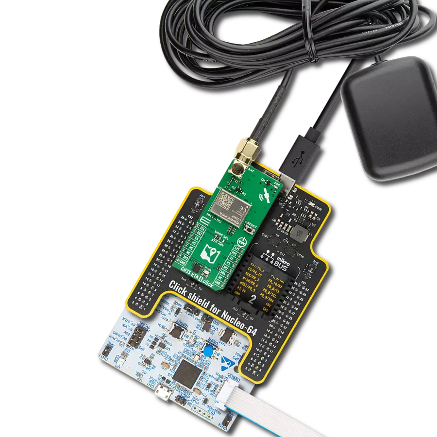
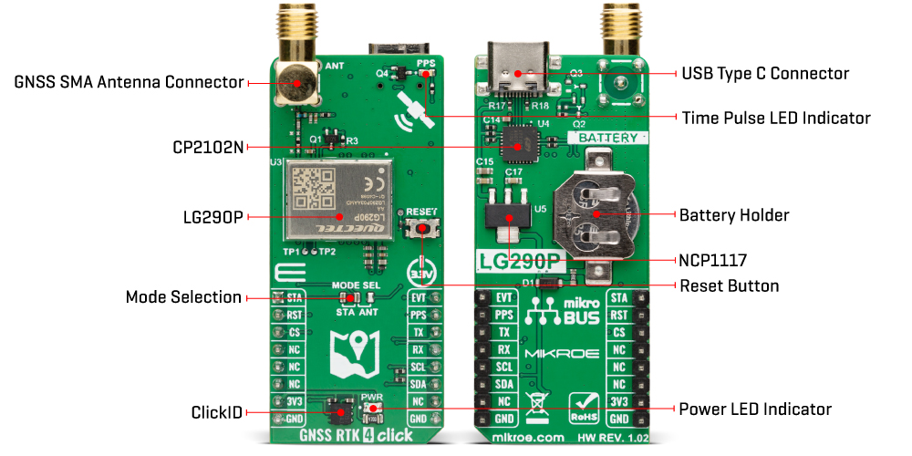
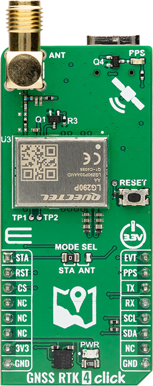
GNSS RTK 4 Click is based on the LG290P, a high-precision GNSS module from Quectel designed for multi-band RTK positioning and multi-constellation support. This module simultaneously receives signals from GPS, GLONASS, Galileo, BDS, QZSS, and NavIC while utilizing SBAS systems (WAAS, EGNOS, BDSBAS, MSAS, GAGAN, and SDCM) to enhance signal accuracy. Its advanced RTK algorithm enables rapid convergence and reliable sub-meter precision, making it ideal for precise navigation in urban areas, industrial applications, and challenging environments with dense foliage. To ensure optimal signal reception in electromagnetically complex environments, the LG290P integrates interference detection and elimination technologies, effectively mitigating multiple narrow-band interference sources. The module also supports multi-mode RTK algorithms, offering fast response times in high-precision positioning scenarios. Beyond positioning accuracy, the LG290P includes Secure Boot, on-chip storage with ECC verification, and integrity monitoring, ensuring firmware security and operational reliability. These features make it well-suited for autonomous navigation, UAVs, intelligent robotics, precision agriculture, surveying, and mining applications. This Click board™ uses the UART
interface as a main communication interface with an additional I2C interface with frequencies up to 400kHz for user-specific cases. It is important to note that firmware does not currently support this interface. Besides, the module also provides an additional UART interface via test points TP1 and TP2 that supports standard NMEA messages and debugging data. This board also includes a USB Type-C connector for USB 2.0 Full Speed capability, allowing for configuration via a PC. This functionality is enabled by the CP2102N, a USB-to-UART bridge, along with the NCP1117 LDO regulator, which converts the USB supply to the necessary 3.3V for the module, allowing for standalone configuration. In case of a power failure, the module can switch to a backup battery, ensuring continuous operation of the real-time clock (RTC) and battery-backed RAM. This preserves critical data and enables faster warm and hot starts. If no battery is present, the backup function is powered via the 3.3V rail of the mikroBUS™ socket. Besides the interface, the GNSS RTK 4 Click includes several pins for additional module control. The EVT pin provides event inputs with adjustable frequency and polarity, allowing for customizable input control. The STA pin indicates the RTK positioning status, where a HIGH
signal signifies that the module is in RTK fix mode, while a LOW signal indicates the module has exited RTK fix mode. This function is available if the MODE SEL jumper is set to the STA position, the default configuration. Alternatively, the STA pin controls the external LNA or active antenna power supply if set to the ANT position. It is important to note that firmware has not yet supported this ANT function. Additionally, the RST pin allows for resetting the module, a function that can also be performed using the onboard RESET button. The GNSS RTK 4 Click has an SMA antenna connector, marked ANT, for connecting an appropriate antenna, also offered by MIKROE, such as a GNSS L1/L5 Active External Antenna. This antenna is an excellent choice for all GNSS applications supporting L1 and L5 band frequencies. Also, the GNSS RTK 4 Click includes a yellow PPS LED indicator, which emits a synchronized pulse signal from the LG290P once per second. This Click board™ can be operated only with a 3.3V logic voltage level. The board must perform appropriate logic voltage level conversion before using MCUs with different logic levels. Also, it comes equipped with a library containing functions and an example code that can be used as a reference for further development.
Features overview
Development board
Nucleo-64 with STM32G474R MCU offers a cost-effective and adaptable platform for developers to explore new ideas and prototype their designs. This board harnesses the versatility of the STM32 microcontroller, enabling users to select the optimal balance of performance and power consumption for their projects. It accommodates the STM32 microcontroller in the LQFP64 package and includes essential components such as a user LED, which doubles as an ARDUINO® signal, alongside user and reset push-buttons, and a 32.768kHz crystal oscillator for precise timing operations. Designed with expansion and flexibility in mind, the Nucleo-64 board features an ARDUINO® Uno V3 expansion connector and ST morpho extension pin
headers, granting complete access to the STM32's I/Os for comprehensive project integration. Power supply options are adaptable, supporting ST-LINK USB VBUS or external power sources, ensuring adaptability in various development environments. The board also has an on-board ST-LINK debugger/programmer with USB re-enumeration capability, simplifying the programming and debugging process. Moreover, the board is designed to simplify advanced development with its external SMPS for efficient Vcore logic supply, support for USB Device full speed or USB SNK/UFP full speed, and built-in cryptographic features, enhancing both the power efficiency and security of projects. Additional connectivity is
provided through dedicated connectors for external SMPS experimentation, a USB connector for the ST-LINK, and a MIPI® debug connector, expanding the possibilities for hardware interfacing and experimentation. Developers will find extensive support through comprehensive free software libraries and examples, courtesy of the STM32Cube MCU Package. This, combined with compatibility with a wide array of Integrated Development Environments (IDEs), including IAR Embedded Workbench®, MDK-ARM, and STM32CubeIDE, ensures a smooth and efficient development experience, allowing users to fully leverage the capabilities of the Nucleo-64 board in their projects.

Microcontroller Overview
MCU Card / MCU

Architecture
ARM Cortex-M4
MCU Memory (KB)
512
Silicon Vendor
STMicroelectronics
Pin count
64
RAM (Bytes)
128k
You complete me!
Accessories
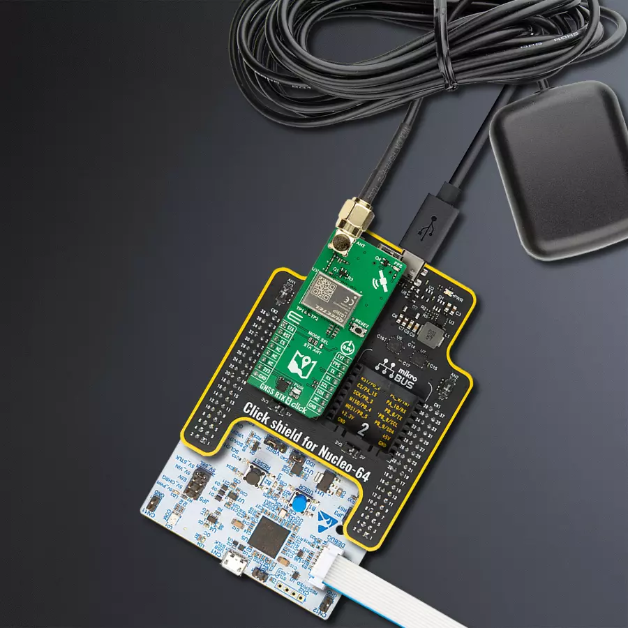
Click Shield for Nucleo-64 comes equipped with two proprietary mikroBUS™ sockets, allowing all the Click board™ devices to be interfaced with the STM32 Nucleo-64 board with no effort. This way, Mikroe allows its users to add any functionality from our ever-growing range of Click boards™, such as WiFi, GSM, GPS, Bluetooth, ZigBee, environmental sensors, LEDs, speech recognition, motor control, movement sensors, and many more. More than 1537 Click boards™, which can be stacked and integrated, are at your disposal. The STM32 Nucleo-64 boards are based on the microcontrollers in 64-pin packages, a 32-bit MCU with an ARM Cortex M4 processor operating at 84MHz, 512Kb Flash, and 96KB SRAM, divided into two regions where the top section represents the ST-Link/V2 debugger and programmer while the bottom section of the board is an actual development board. These boards are controlled and powered conveniently through a USB connection to program and efficiently debug the Nucleo-64 board out of the box, with an additional USB cable connected to the USB mini port on the board. Most of the STM32 microcontroller pins are brought to the IO pins on the left and right edge of the board, which are then connected to two existing mikroBUS™ sockets. This Click Shield also has several switches that perform functions such as selecting the logic levels of analog signals on mikroBUS™ sockets and selecting logic voltage levels of the mikroBUS™ sockets themselves. Besides, the user is offered the possibility of using any Click board™ with the help of existing bidirectional level-shifting voltage translators, regardless of whether the Click board™ operates at a 3.3V or 5V logic voltage level. Once you connect the STM32 Nucleo-64 board with our Click Shield for Nucleo-64, you can access hundreds of Click boards™, working with 3.3V or 5V logic voltage levels.

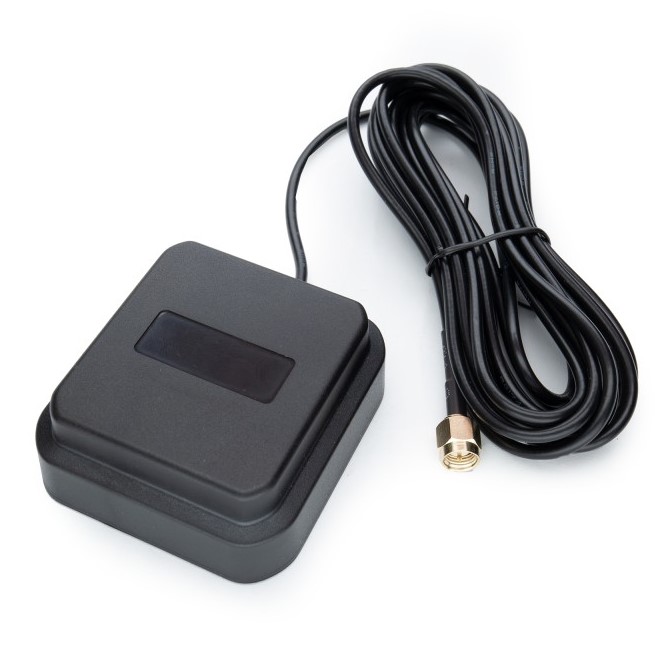
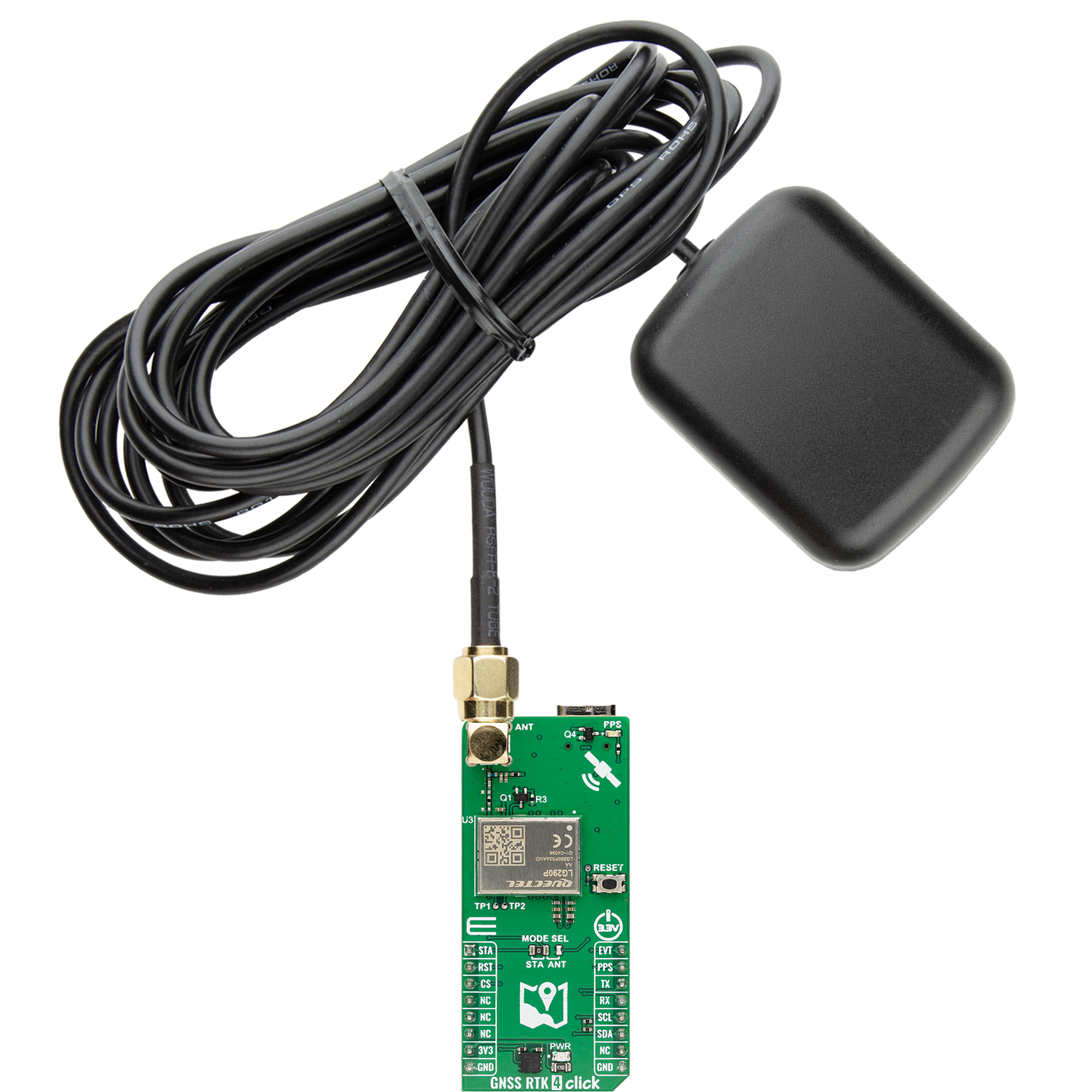
GNSS L1/L5 Active External Antenna (YB0017AA) is an active patch antenna from Quectel that supports GNSS L1/L5 BD B1/B2 GLONASS L1, offering excellent performance with its high gain and efficiency for fleet management, navigation, RTK, and many other tracking applications. The magnetic-mounting antenna, with dimensions of 61.5×56.5×23mm, is designed to work with various ground plane sizes or in free space and is connected to the device by a 3m cable with an SMA male connector.
Used MCU Pins
mikroBUS™ mapper
Take a closer look
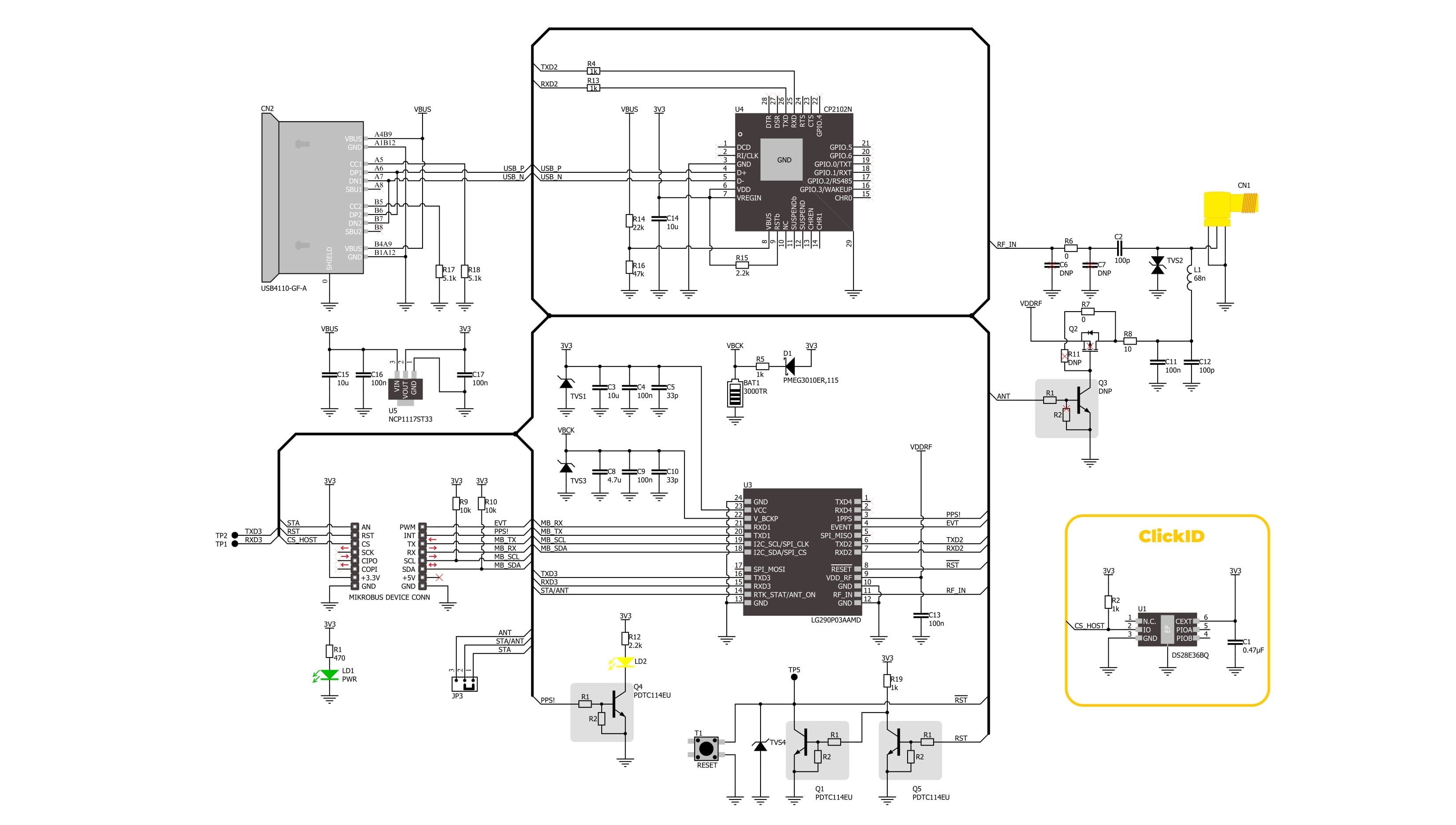
Click board™ Schematic
Step by step
Project assembly
Start by selecting your development board and Click board™. Begin with the Nucleo 64 with STM32G474RE MCU as your development board.


Software Support
Library Description
GNSS RTK 4 Click demo application is developed using the NECTO Studio, ensuring compatibility with mikroSDK's open-source libraries and tools. Designed for plug-and-play implementation and testing, the demo is fully compatible with all development, starter, and mikromedia boards featuring a mikroBUS™ socket.
Example Description
This example demonstrates the use of GNSS RTK 4 Click by reading and displaying the GNSS coordinates.
Key functions:
gnssrtk4_cfg_setup- This function initializes Click configuration structure to initial values.gnssrtk4_init- This function initializes all necessary pins and peripherals used for this Click board.gnssrtk4_generic_read- This function reads a desired number of data bytes by using UART serial interface.gnssrtk4_parse_gga- This function parses the GGA data from the read response buffer.gnssrtk4_reset_device- This function resets the device by toggling the RST pin.
Application Init
Initializes the driver and logger.
Application Task
Reads the received data, parses the NMEA GGA info from it, and once it receives the position fix it will start displaying the coordinates on the USB UART.
Open Source
Code example
The complete application code and a ready-to-use project are available through the NECTO Studio Package Manager for direct installation in the NECTO Studio. The application code can also be found on the MIKROE GitHub account.
/*!
 * @file main.c
 * @brief GNSS RTK 4 Click Example.
 *
 * # Description
 * This example demonstrates the use of GNSS RTK 4 Click by reading and displaying
 * the GNSS coordinates.
 *
 * The demo application is composed of two sections :
 *
 * ## Application Init
 * Initializes the driver and logger.
 *
 * ## Application Task
 * Reads the received data, parses the NMEA GGA info from it, and once it receives
 * the position fix it will start displaying the coordinates on the USB UART.
 *
 * ## Additional Function
 * - static void gnssrtk4_clear_app_buf ( void )
 * - static void gnssrtk4_log_app_buf ( void )
 * - static err_t gnssrtk4_process ( gnssrtk4_t *ctx )
 * - static void gnssrtk4_parser_application ( uint8_t *rsp )
 *
 * @note
 * The Click board comes with the default baud rate of 460800, but the baud rate is set to 115200
 * in the library due to code portability and speed limitations of some MCUs. So in order to run
 * the example you will need to adjust the baud rate using Quectel QGNSS evaluation software.
 *
 * @author Stefan Filipovic
 *
 */

#include "board.h"
#include "log.h"
#include "gnssrtk4.h"

// Application buffer size
#define APP_BUFFER_SIZE     500
#define PROCESS_BUFFER_SIZE 200

static gnssrtk4_t gnssrtk4;
static log_t logger;

static uint8_t app_buf[ APP_BUFFER_SIZE ] = { 0 };
static int32_t app_buf_len = 0;

/**
 * @brief GNSS RTK 4 clearing application buffer.
 * @details This function clears memory of application buffer and reset its length.
 * @note None.
 */
static void gnssrtk4_clear_app_buf ( void );

/**
 * @brief GNSS RTK 4 log application buffer.
 * @details This function logs data from application buffer to USB UART.
 * @note None.
 */
static void gnssrtk4_log_app_buf ( void );

/**
 * @brief GNSS RTK 4 data reading function.
 * @details This function reads data from device and concatenates data to application buffer.
 * @param[in] ctx : Click context object.
 * See #gnssrtk4_t object definition for detailed explanation.
 * @return @li @c  0 - Read some data.
 *         @li @c -1 - Nothing is read.
 * See #err_t definition for detailed explanation.
 * @note None.
 */
static err_t gnssrtk4_process ( gnssrtk4_t *ctx );

/**
 * @brief GNSS RTK 4 parser application.
 * @details This function logs GNSS data on the USB UART.
 * @param[in] rsp : Response buffer.
 * @return None.
 * @note None.
 */
static void gnssrtk4_parser_application ( uint8_t *rsp );

void application_init ( void )
{
    log_cfg_t log_cfg;  /**< Logger config object. */
    gnssrtk4_cfg_t gnssrtk4_cfg;  /**< Click config object. */

    /**
     * Logger initialization.
     * Default baud rate: 115200
     * Default log level: LOG_LEVEL_DEBUG
     * @note If USB_UART_RX and USB_UART_TX
     * are defined as HAL_PIN_NC, you will
     * need to define them manually for log to work.
     * See @b LOG_MAP_USB_UART macro definition for detailed explanation.
     */
    LOG_MAP_USB_UART( log_cfg );
    log_init( &logger, &log_cfg );
    log_info( &logger, " Application Init " );

    // Click initialization.
    gnssrtk4_cfg_setup( &gnssrtk4_cfg );
    GNSSRTK4_MAP_MIKROBUS( gnssrtk4_cfg, MIKROBUS_1 );
    if ( UART_ERROR == gnssrtk4_init( &gnssrtk4, &gnssrtk4_cfg ) )
    {
        log_error( &logger, " Communication init." );
        for ( ; ; );
    }

    log_info( &logger, " Application Task " );
}

void application_task ( void )
{
    if ( GNSSRTK4_OK == gnssrtk4_process( &gnssrtk4 ) )
    {
        gnssrtk4_parser_application( app_buf );
    }
}

int main ( void )
{
    /* Do not remove this line or clock might not be set correctly. */
    #ifdef PREINIT_SUPPORTED
    preinit();
    #endif

    application_init( );

    for ( ; ; )
    {
        application_task( );
    }

    return 0;
}

static void gnssrtk4_clear_app_buf ( void )
{
    memset( app_buf, 0, app_buf_len );
    app_buf_len = 0;
}

static void gnssrtk4_log_app_buf ( void )
{
    for ( int32_t buf_cnt = 0; buf_cnt < app_buf_len; buf_cnt++ )
    {
        log_printf( &logger, "%c", app_buf[ buf_cnt ] );
    }
}

static err_t gnssrtk4_process ( gnssrtk4_t *ctx )
{
    uint8_t rx_buf[ PROCESS_BUFFER_SIZE ] = { 0 };
    int32_t overflow_bytes = 0;
    int32_t rx_cnt = 0;
    int32_t rx_size = gnssrtk4_generic_read( ctx, rx_buf, PROCESS_BUFFER_SIZE );
    if ( ( rx_size > 0 ) && ( rx_size <= APP_BUFFER_SIZE ) )
    {
        if ( ( app_buf_len + rx_size ) > APP_BUFFER_SIZE )
        {
            overflow_bytes = ( app_buf_len + rx_size ) - APP_BUFFER_SIZE;
            app_buf_len = APP_BUFFER_SIZE - rx_size;
            memmove ( app_buf, &app_buf[ overflow_bytes ], app_buf_len );
            memset ( &app_buf[ app_buf_len ], 0, overflow_bytes );
        }
        for ( rx_cnt = 0; rx_cnt < rx_size; rx_cnt++ )
        {
            if ( rx_buf[ rx_cnt ] )
            {
                app_buf[ app_buf_len++ ] = rx_buf[ rx_cnt ];
            }
        }
        return GNSSRTK4_OK;
    }
    return GNSSRTK4_ERROR;
}

static void gnssrtk4_parser_application ( uint8_t *rsp )
{
    uint8_t element_buf[ 200 ] = { 0 };
    if ( GNSSRTK4_OK == gnssrtk4_parse_gga( rsp, GNSSRTK4_GGA_LATITUDE, element_buf ) )
    {
        static uint8_t wait_for_fix_cnt = 0;
        if ( strlen( element_buf ) > 0 )
        {
            log_printf( &logger, "\r\n Latitude: %.2s degrees, %s minutes \r\n", element_buf, &element_buf[ 2 ] );
            memset( element_buf, 0, sizeof( element_buf ) );
            gnssrtk4_parse_gga( rsp, GNSSRTK4_GGA_LONGITUDE, element_buf );
            log_printf( &logger, " Longitude: %.3s degrees, %s minutes \r\n", element_buf, &element_buf[ 3 ] );
            memset( element_buf, 0, sizeof( element_buf ) );
            gnssrtk4_parse_gga( rsp, GNSSRTK4_GGA_ALTITUDE, element_buf );
            log_printf( &logger, " Altitude: %s m \r\n", element_buf );
            wait_for_fix_cnt = 0;
        }
        else
        {
            if ( wait_for_fix_cnt % 50 == 0 )
            {
                log_printf( &logger, " Waiting for the position fix...\r\n\n" );
                wait_for_fix_cnt = 0;
            }
            wait_for_fix_cnt++;
        }
        gnssrtk4_clear_app_buf(  );
    }
}

// ------------------------------------------------------------------------ END
Additional Support
Resources
Category:GPS/GNSS


