Boost voltage with ultra-low power consumption using MAX17250 and ATmega328P
DC-DC synchronous boost converter with True Shutdown™

Published Feb 27, 2025
Click board™
Boost 5 Click
Dev. board
Arduino UNO Rev3
Compiler
NECTO Studio
MCU
ATmega328P
Boost voltage with ultra-low power consumption and True Shutdown™ perfect for battery-powered IoT devices, display power, and alarm drivers
A
A
Hardware Overview
How does it work?
Boost 5 Click is based on the MAX17250, a DC-DC synchronous step-up converter from Analog Devices. Designed to deliver exceptional power efficiency with minimal energy consumption, this Click board™ is ideal for battery-powered applications requiring a stable and reliable voltage boost. With its wide input voltage range, the MAX17250 steps up the voltage to as high as 14V (with peak current limit of 3.5A) while maintaining a low quiescent current operation. One of its standout features is True Shutdown™. This unique capability ensures complete disconnection of the output from the input, reducing battery drain to a mere 0.1µA in shutdown mode, significantly extending battery life in portable and low-power applications, including battery-powered IoT devices, single or dual-cell Li-Ion battery-powered systems, buzzer/alarm drivers, as well as display power supplies. The MAX17250 operates in three operational modes to optimize performance based on the system’s requirements. At startup, the soft-start mode ensures a smooth
power-up sequence, preventing inrush currents that could destabilize the system. Once operational, the converter functions using a fixed on-time and minimum off-time Pulse Frequency Modulation (PFM) architecture, which only activates the switching regulator when necessary, achieving an ultra-low typical quiescent current of just 60µA. Additionally, its integrated short-circuit protection further enhance reliability and safe operation under varying load conditions. This Click board™ features a four-position switch that allows users to select the desired regulated output voltage at the VOUT terminal, providing flexibility for different application needs. The switch positions correspond to four preset voltage levels: 8V at position 0, 10V at position 1, 12V at position 2, and 14V at position 3. Additionally, the board includes two pins for enhanced operation and monitoring. The EN pin serves as a device-enable control, allowing the user to activate or deactivate the boost converter as needed, while the AN pin functions as a digital
output, providing real-time feedback on the board’s output voltage at the VOUT terminal. Boost 5 Click also offers versatile power sourcing options, allowing users to choose between internal and external supplies to best suit their application needs. This flexibility is achieved through the VIN SEL jumper, which enables users to select the 5V position for sourcing power internally via the 5V mikroBUS™ power rail or the EXT position to connect an external power supply (supplied via the VEXT terminal). The external power supply can range from 2.7V to 18V, providing a wide voltage range for various project requirements. This Click board™ can operate with either 3.3V or 5V logic voltage levels selected via the VCC SEL jumper. This way, both 3.3V and 5V capable MCUs can use the communication lines properly. Also, this Click board™ comes equipped with a library containing easy-to-use functions and an example code that can be used as a reference for further development.

Features overview
Development board
Arduino UNO is a versatile microcontroller board built around the ATmega328P chip. It offers extensive connectivity options for various projects, featuring 14 digital input/output pins, six of which are PWM-capable, along with six analog inputs. Its core components include a 16MHz ceramic resonator, a USB connection, a power jack, an
ICSP header, and a reset button, providing everything necessary to power and program the board. The Uno is ready to go, whether connected to a computer via USB or powered by an AC-to-DC adapter or battery. As the first USB Arduino board, it serves as the benchmark for the Arduino platform, with "Uno" symbolizing its status as the
first in a series. This name choice, meaning "one" in Italian, commemorates the launch of Arduino Software (IDE) 1.0. Initially introduced alongside version 1.0 of the Arduino Software (IDE), the Uno has since become the foundational model for subsequent Arduino releases, embodying the platform's evolution.

Microcontroller Overview
MCU Card / MCU

Architecture
AVR
MCU Memory (KB)
32
Silicon Vendor
Microchip
Pin count
28
RAM (Bytes)
2048
You complete me!
Accessories
Click Shield for Arduino UNO has two proprietary mikroBUS™ sockets, allowing all the Click board™ devices to be interfaced with the Arduino UNO board without effort. The Arduino Uno, a microcontroller board based on the ATmega328P, provides an affordable and flexible way for users to try out new concepts and build prototypes with the ATmega328P microcontroller from various combinations of performance, power consumption, and features. The Arduino Uno has 14 digital input/output pins (of which six can be used as PWM outputs), six analog inputs, a 16 MHz ceramic resonator (CSTCE16M0V53-R0), a USB connection, a power jack, an ICSP header, and reset button. Most of the ATmega328P microcontroller pins are brought to the IO pins on the left and right edge of the board, which are then connected to two existing mikroBUS™ sockets. This Click Shield also has several switches that perform functions such as selecting the logic levels of analog signals on mikroBUS™ sockets and selecting logic voltage levels of the mikroBUS™ sockets themselves. Besides, the user is offered the possibility of using any Click board™ with the help of existing bidirectional level-shifting voltage translators, regardless of whether the Click board™ operates at a 3.3V or 5V logic voltage level. Once you connect the Arduino UNO board with our Click Shield for Arduino UNO, you can access hundreds of Click boards™, working with 3.3V or 5V logic voltage levels.

Used MCU Pins
mikroBUS™ mapper
Take a closer look
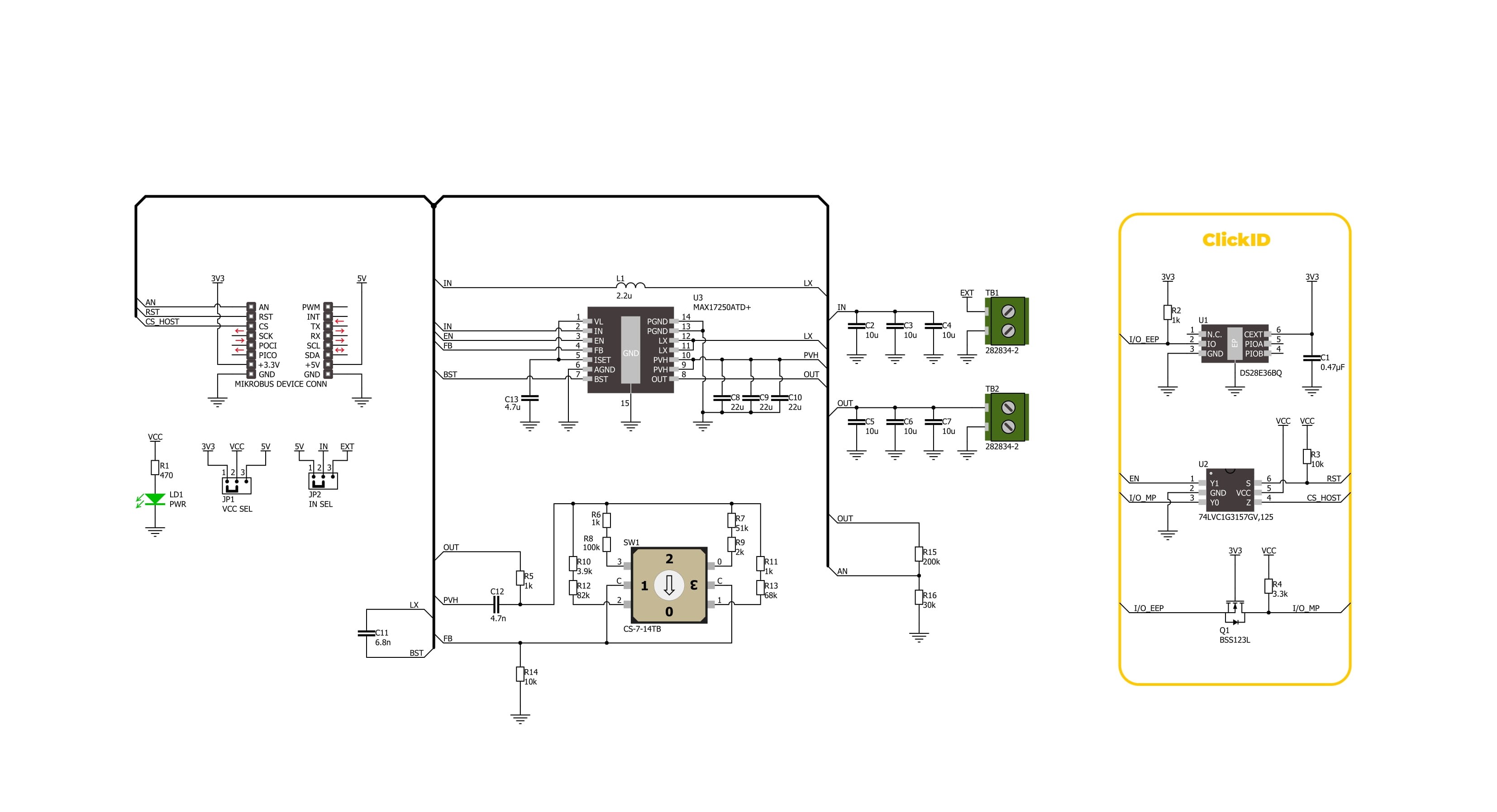
Click board™ Schematic
Step by step
Project assembly

Start by selecting your development board and Click board™. Begin with the Arduino UNO Rev3 as your development board.


Software Support
Library Description
Boost 5 Click demo application is developed using the NECTO Studio, ensuring compatibility with mikroSDK's open-source libraries and tools. Designed for plug-and-play implementation and testing, the demo is fully compatible with all development, starter, and mikromedia boards featuring a mikroBUS™ socket.
Example Description
This example demonstrates the use of the Boost 5 Click board by enabling the device and continuously reading and logging the measured output voltage (VOUT). If a failure is detected during voltage reading, the device is reset.
Key functions:
boost5_cfg_setup- This function initializes Click configuration structure to initial values.boost5_init- This function initializes all necessary pins and peripherals used for this Click board.boost5_enable_device- This function enables device by setting the EN pin to high logic state.boost5_reset_device- This function resets device by toggling the EN pin logic state.boost5_read_vout- This function reads the boost output voltage level.
Application Init
Initializes the logger and the Boost 5 Click board. Configures the ADC for voltage measurements and enables the device to prepare it for operation.
Application Task
Reads the output voltage level and logs it on the USB UART. In case of an error during the reading process, or the user changes VOUT using an on-board VOUT SEL switch, the device is reset to recover from potential issues or to apply new settings.
Open Source
Code example
The complete application code and a ready-to-use project are available through the NECTO Studio Package Manager for direct installation in the NECTO Studio. The application code can also be found on the MIKROE GitHub account.
/*!
 * @file main.c
 * @brief Boost 5 Click Example.
 *
 * # Description
 * This example demonstrates the use of the Boost 5 Click board by enabling the device
 * and continuously reading and logging the measured output voltage (VOUT).
 * If a failure is detected during voltage reading, the device is reset.
 *
 * The demo application is composed of two sections:
 *
 * ## Application Init
 * Initializes the logger and the Boost 5 Click board. Configures the ADC for voltage
 * measurements and enables the device to prepare it for operation.
 *
 * ## Application Task
 * Reads the output voltage level and logs it on the USB UART. In case of an error during
 * the reading process, or the user changes VOUT using an on-board VOUT SEL switch,
 * the device is reset to recover from potential issues or to apply new settings.
 *
 * @note
 * The VOUT is configured using an on-board VOUT SEL 4-position switch.
 *
 * @author Stefan Filipovic
 *
 */

#include "board.h"
#include "log.h"
#include "boost5.h"

static boost5_t boost5;   /**< Boost 5 Click driver object. */
static log_t logger;    /**< Logger object. */

void application_init ( void )
{
    log_cfg_t log_cfg;  /**< Logger config object. */
    boost5_cfg_t boost5_cfg;  /**< Click config object. */

    /**
     * Logger initialization.
     * Default baud rate: 115200
     * Default log level: LOG_LEVEL_DEBUG
     * @note If USB_UART_RX and USB_UART_TX
     * are defined as HAL_PIN_NC, you will
     * need to define them manually for log to work.
     * See @b LOG_MAP_USB_UART macro definition for detailed explanation.
     */
    LOG_MAP_USB_UART( log_cfg );
    log_init( &logger, &log_cfg );
    log_info( &logger, " Application Init " );

    // Click initialization.
    boost5_cfg_setup( &boost5_cfg );
    BOOST5_MAP_MIKROBUS( boost5_cfg, MIKROBUS_1 );
    if ( ADC_ERROR == boost5_init( &boost5, &boost5_cfg ) )
    {
        log_error( &logger, " Communication init." );
        for ( ; ; );
    }

    log_printf( &logger, "\r\n Enable device\r\n\n" );
    boost5_enable_device ( &boost5 );

    log_info( &logger, " Application Task " );
}

void application_task ( void )
{
    float vout = 0;
    if ( BOOST5_OK == boost5_read_vout ( &boost5, &vout ) )
    {
        log_printf( &logger, "\r\n VOUT : %.3f V\r\n", vout );
    }
    else
    {
        log_printf( &logger, "\r\n Reset device\r\n" );
        boost5_reset_device ( &boost5 );
    }
}

int main ( void )
{
    /* Do not remove this line or clock might not be set correctly. */
    #ifdef PREINIT_SUPPORTED
    preinit();
    #endif

    application_init( );

    for ( ; ; )
    {
        application_task( );
    }

    return 0;
}

// ------------------------------------------------------------------------ END
Additional Support
Resources
Category:Boost


