Achieve differential pressure measurements with MPXV5010DP and PIC32MX470F512H
Dual port differential pressure sensing solution
Published Mar 24, 2025
Click board™
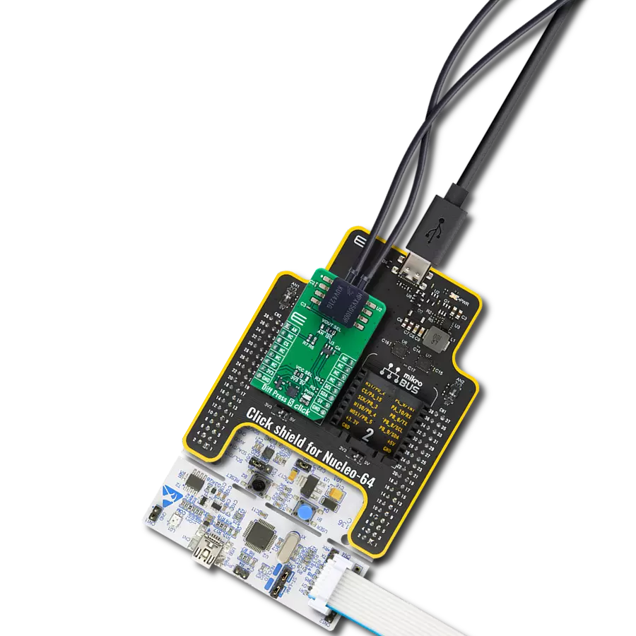
Diff Press 5 Click
Dev. board
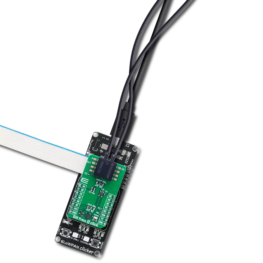
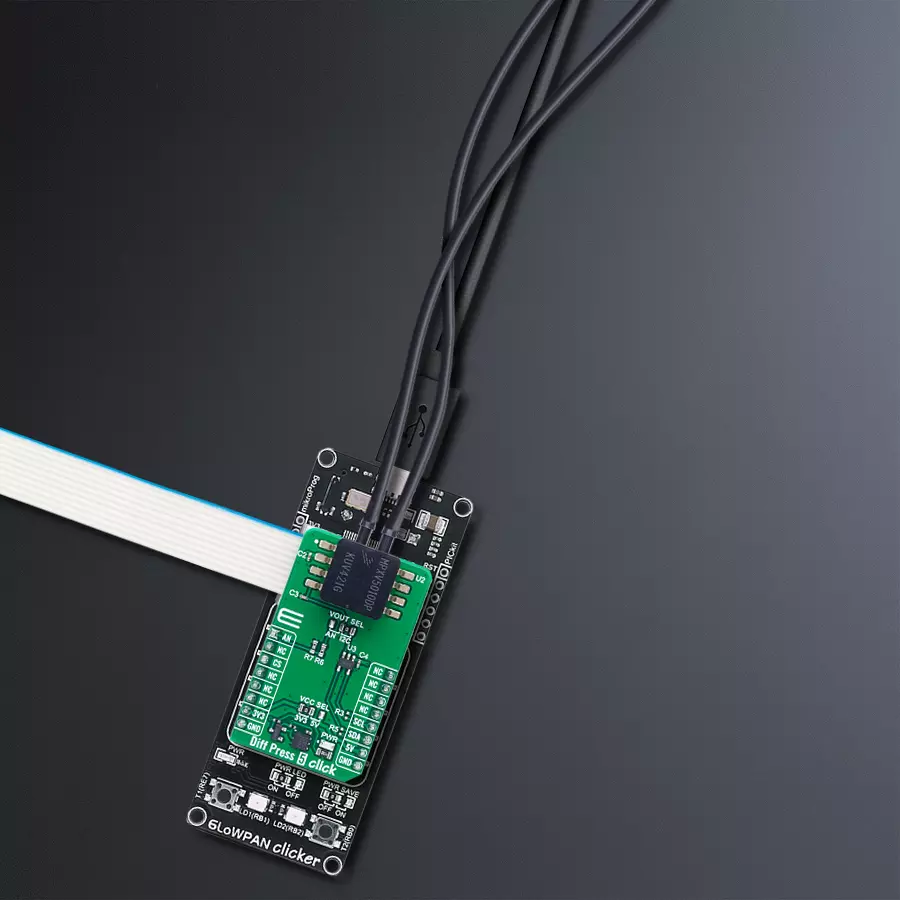
6LoWPAN clicker
Compiler
NECTO Studio
MCU
PIC32MX470F512H
Measure differential pressure with high precision and stability for industrial and medical applications
A
A
Hardware Overview
How does it work?
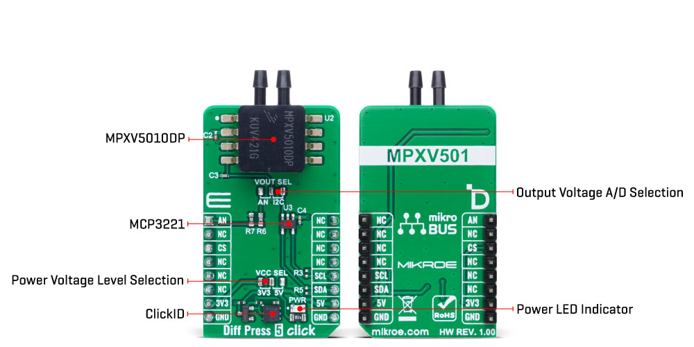
Diff Press 5 Click is based on the MPXV5010DP, a high-precision dual port differential pressure sensor from NXP, designed to deliver accurate and reliable pressure readings across a variety of applications, particularly those involving microcontrollers or microprocessors equipped with A/D inputs. At its core, the MPXV5010DP is a piezoresistive transducer that uses state-of-the-art monolithic silicon technology to ensure high performance. By integrating micromachining techniques, thin-film metallization, and bipolar processing, this sensor provides a precise and proportional analog output signal in response to applied pressure. Its axial port has been specially adapted to accommodate industrial-grade tubing, making it suitable for use in demanding environments. A key feature of this sensor is its built-in temperature compensation and
calibration, achieved through the integration of shear-stress strain gauge technology, signal conditioning, and compensation circuitry within a single monolithic chip. This ensures consistent performance across a range of operating conditions. Housed in a durable epoxy unibody and thermoplastic (PPS) surface-mount package, the MPXV5010DP supports a pressure range from 0 to 10kPa (equivalent to 1019.78mm H2O) with a typical sensitivity of 450mV/kPa (4.413mV/kPa H2O). Diff Press 5 Click is well-suited for use in HVAC systems, respiratory monitoring devices, process control applications, liquid level sensing in appliances, and other scenarios where accurate differential pressure measurement is essential. The MPXV5010DP's analog output can also be converted to a digital value using MCP3221, a 12-
bit successive approximation A/D converter from Microchip, using a 2-wire I2C compatible interface, or sent, as mentioned, directly to an analog output pin of the mikroBUS™ socket labeled as AN. Selection can be performed via an onboard SMD jumper labeled VOUT SEL, placing it in an appropriate position marked as AN and I2C. This Click board™ can operate with either 3.3V or 5V logic voltage levels selected via the VCC SEL jumper. This way, both 3.3V and 5V capable MCUs can use the communication lines properly. Also, this Click board™ comes equipped with a library containing easy-to-use functions and an example code that can be used as a reference for further development.
Features overview
Development board
6LoWPAN Clicker is a compact starter development board that brings the flexibility of add-on Click boards™ to your favorite microcontroller, making it a perfect starter kit for implementing your ideas. It comes with an onboard 32-bit PIC microcontroller, the PIC32MX470F512H from Microchip, a USB connector, LED indicators, buttons, a mikroProg connector, and a header for interfacing with external electronics. Along with this microcontroller, the board also contains a 2.4GHz ISM band transceiver, allowing you to add wireless communication to your target application. Its compact design provides a fluid and immersive working experience, allowing access anywhere
and under any circumstances. Each part of the 6LoWPAN Clicker development kit contains the components necessary for the most efficient operation of the same board. In addition to the possibility of choosing the 6LoWPAN Clicker programming method, using USB HID mikroBootloader, or through an external mikroProg connector for PIC, dsPIC, or PIC32 programmer, the Clicker board also includes a clean and regulated power supply module for the development kit. The USB Micro-B connection can provide up to 500mA of current for the Clicker board, which is more than enough to operate all onboard and additional modules, or it can power
over two standard AA batteries. All communication methods that mikroBUS™ itself supports are on this board, including the well-established mikroBUS™ socket, reset button, and several buttons and LED indicators. 6LoWPAN Clicker is an integral part of the Mikroe ecosystem, allowing you to create a new application in minutes. Natively supported by Mikroe software tools, it covers many aspects of prototyping thanks to a considerable number of different Click boards™ (over a thousand boards), the number of which is growing every day.

Microcontroller Overview
MCU Card / MCU

Architecture
PIC32
MCU Memory (KB)
512
Silicon Vendor
Microchip
Pin count
64
RAM (Bytes)
131072
Used MCU Pins
mikroBUS™ mapper
Take a closer look
Click board™ Schematic

Step by step
Project assembly

Start by selecting your development board and Click board™. Begin with the 6LoWPAN clicker as your development board.


Track your results in real time
Application Output
1. Application Output - In Debug mode, the 'Application Output' window enables real-time data monitoring, offering direct insight into execution results. Ensure proper data display by configuring the environment correctly using the provided tutorial.

2. UART Terminal - Use the UART Terminal to monitor data transmission via a USB to UART converter, allowing direct communication between the Click board™ and your development system. Configure the baud rate and other serial settings according to your project's requirements to ensure proper functionality. For step-by-step setup instructions, refer to the provided tutorial.

3. Plot Output - The Plot feature offers a powerful way to visualize real-time sensor data, enabling trend analysis, debugging, and comparison of multiple data points. To set it up correctly, follow the provided tutorial, which includes a step-by-step example of using the Plot feature to display Click board™ readings. To use the Plot feature in your code, use the function: plot(*insert_graph_name*, variable_name);. This is a general format, and it is up to the user to replace 'insert_graph_name' with the actual graph name and 'variable_name' with the parameter to be displayed.

Software Support
Library Description
Diff Press 5 Click demo application is developed using the NECTO Studio, ensuring compatibility with mikroSDK's open-source libraries and tools. Designed for plug-and-play implementation and testing, the demo is fully compatible with all development, starter, and mikromedia boards featuring a mikroBUS™ socket.
Example Description
This example demonstrates the use of the Diff Press 5 Click board. It showcases how to initialize the device, calibrate the zero-pressure offset, and read the differential pressure data in Pascals (Pa) from the sensor.
Key functions:
diffpress5_cfg_setup- Config Object Initialization function.diffpress5_init- Initialization function.diffpress5_default_cfg- Click Default Configuration function.diffpress5_calib_offset- This function calibrates the zero current offset value.diffpress5_read_vout_avg- This function reads a desired number of sensor voltage output samples and averages it.diffpress5_read_pressure- This function reads the differential pressure measurement.
Application Init
Initializes the logger and the Diff Press 5 Click driver. The application then performs zero-pressure offset calibration to ensure accurate pressure measurements. During the calibration, it is crucial to avoid applying pressure to the sensor.
Application Task
Continuously reads the differential pressure from the sensor and logs the values in Pascals (Pa).
Open Source
Code example
The complete application code and a ready-to-use project are available through the NECTO Studio Package Manager for direct installation in the NECTO Studio. The application code can also be found on the MIKROE GitHub account.
/*!
 * @file main.c
 * @brief Diff Press 5 Click Example.
 *
 * # Description
 * This example demonstrates the use of the Diff Press 5 Click board. It showcases how to initialize the device,
 * calibrate the zero-pressure offset, and read the differential pressure data in Pascals (Pa) from the sensor.
 *
 * The demo application is composed of two sections:
 *
 * ## Application Init
 * Initializes the logger and the Diff Press 5 Click driver. The application then performs zero-pressure
 * offset calibration to ensure accurate pressure measurements. During the calibration, it is crucial to avoid
 * applying pressure to the sensor.
 *
 * ## Application Task
 * Continuously reads the differential pressure from the sensor and logs the values in Pascals (Pa).
 *
 * @note
 * The measurable pressure range of the sensor is 0 to 10000 Pa.
 *
 * @author Stefan Filipovic
 *
 */


#include "board.h"
#include "log.h"
#include "diffpress5.h"

static diffpress5_t diffpress5;   /**< Diff Press 5 Click driver object. */
static log_t logger;    /**< Logger object. */

void application_init ( void )
{
    log_cfg_t log_cfg;  /**< Logger config object. */
    diffpress5_cfg_t diffpress5_cfg;  /**< Click config object. */

    /**
     * Logger initialization.
     * Default baud rate: 115200
     * Default log level: LOG_LEVEL_DEBUG
     * @note If USB_UART_RX and USB_UART_TX
     * are defined as HAL_PIN_NC, you will
     * need to define them manually for log to work.
     * See @b LOG_MAP_USB_UART macro definition for detailed explanation.
     */
    LOG_MAP_USB_UART( log_cfg );
    log_init( &logger, &log_cfg );
    log_info( &logger, " Application Init " );

    // Click initialization.
    diffpress5_cfg_setup( &diffpress5_cfg );
    DIFFPRESS5_MAP_MIKROBUS( diffpress5_cfg, MIKROBUS_1 );
    err_t init_flag = diffpress5_init( &diffpress5, &diffpress5_cfg );
    if ( ( ADC_ERROR == init_flag ) || ( I2C_MASTER_ERROR == init_flag ) )
    {
        log_error( &logger, " Communication init." );
        for ( ; ; );
    }

    log_printf( &logger, " Calibrating zero pressure offset in 5 seconds...\r\n" );
    log_printf( &logger, " Make sure no pressure is applied to the sensor during the calibration process.\r\n" );
    for ( uint8_t cnt = 5; cnt > 0; cnt-- )
    {
        log_printf( &logger, " %u\r\n", ( uint16_t ) cnt );
        Delay_ms ( 1000 );
    }
    if ( DIFFPRESS5_ERROR == diffpress5_calib_offset ( &diffpress5 ) )
    {
        log_error( &logger, " Calibrate offset." );
        for ( ; ; );
    }
    log_printf( &logger, " Offset calibration DONE.\r\n\n" );

    log_info( &logger, " Application Task " );
}

void application_task ( void )
{
    uint16_t pressure = 0;
    if ( DIFFPRESS5_OK == diffpress5_read_pressure ( &diffpress5, &pressure ) )
    {
        log_printf( &logger, " Pressure : %u Pa\r\n\n", pressure );
    }
}

int main ( void )
{
    /* Do not remove this line or clock might not be set correctly. */
    #ifdef PREINIT_SUPPORTED
    preinit();
    #endif

    application_init( );

    for ( ; ; )
    {
        application_task( );
    }

    return 0;
}

// ------------------------------------------------------------------------ END
Additional Support
Resources
Category:Pressure