Achieve pressure measurements up to 2kPa with MPXV7002 and PIC18F47K42
Pressure/Vacuum sensing ideal for automotive and non-automotive applications

Published Mar 17, 2025
Click board™
Vacuum 2 Click
Dev. board
EasyPIC v8
Compiler
NECTO Studio
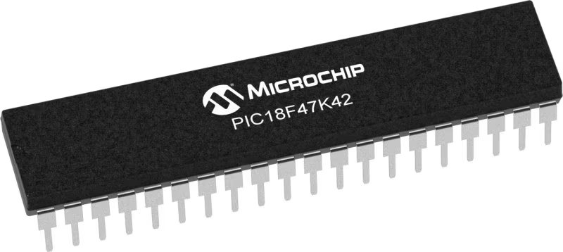
MCU
PIC18F47K42
Measure pressure with high accuracy and reliability in HVAC systems, respiratory monitoring, and process control
A
A
Hardware Overview
How does it work?
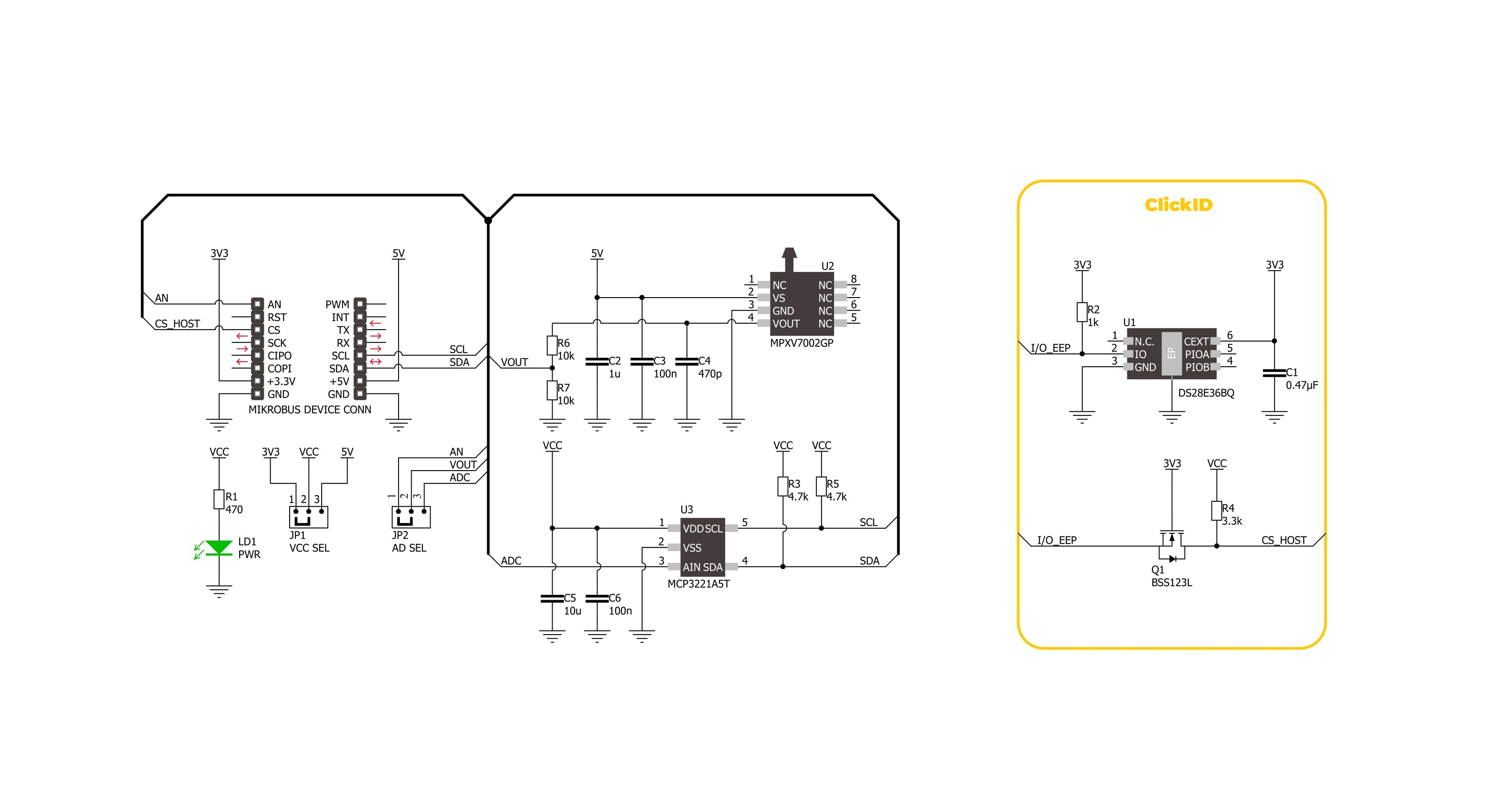
Vacuum 2 Click is based on the MPXV7002, an integrated on-chip signal-conditioned, temperature-compensated, and calibrated silicon pressure sensor from NXP. It provides precise pressure measurement capabilities, making it an excellent choice for various industrial and medical applications. At the core of Vacuum 2 Click, the MPXV7002 functions as a piezoresistive transducer built on monolithic silicon technology. It integrates cutting-edge micromachining techniques, thin-film metallization, and bipolar processing to achieve a high-level analog output signal directly proportional to the applied pressure. As a single-port gauge pressure sensor, it employs a patented silicon shear stress strain gauge configuration, enabling
precise pressure measurements. Designed to operate efficiently within a temperature range of +10°C to +60°C, the MPXV7002 ensures stable performance across varying environmental conditions. It offers a pressure measurement range from -2kPa to 2kPa, with a typical sensitivity of 1V/kPa, making it highly suitable for applications that require fine pressure adjustments and monitoring. Common use cases include HVAC systems, respiratory monitoring equipment, and industrial process control, where accurate pressure sensing plays a crucial role in optimizing performance and safety. The MPXV7002's analog output can also be converted to a digital value using MCP3221, a successive approximation A/D
converter with a 12-bit resolution from Microchip, using a 2-wire I2C compatible interface, or sent, as mentioned, directly to an analog output pin of the mikroBUS™ socket labeled as AN. Selection can be performed via an onboard SMD jumper labeled AD SEL, placing it in an appropriate position marked as AN and ADC. This Click board™ can operate with either 3.3V or 5V logic voltage levels selected via the VCC SEL jumper. This way, both 3.3V and 5V capable MCUs can use the communication lines properly. Also, this Click board™ comes equipped with a library containing easy-to-use functions and an example code that can be used as a reference for further development.

Features overview
Development board
EasyPIC v8 is a development board specially designed for the needs of rapid development of embedded applications. It supports many high pin count 8-bit PIC microcontrollers from Microchip, regardless of their number of pins, and a broad set of unique functions, such as the first-ever embedded debugger/programmer. The development board is well organized and designed so that the end-user has all the necessary elements, such as switches, buttons, indicators, connectors, and others, in one place. Thanks to innovative manufacturing technology, EasyPIC v8 provides a fluid and immersive working experience, allowing access anywhere and under any
circumstances at any time. Each part of the EasyPIC v8 development board contains the components necessary for the most efficient operation of the same board. In addition to the advanced integrated CODEGRIP programmer/debugger module, which offers many valuable programming/debugging options and seamless integration with the Mikroe software environment, the board also includes a clean and regulated power supply module for the development board. It can use a wide range of external power sources, including a battery, an external 12V power supply, and a power source via the USB Type-C (USB-C) connector.
Communication options such as USB-UART, USB DEVICE, and CAN are also included, including the well-established mikroBUS™ standard, two display options (graphical and character-based LCD), and several different DIP sockets. These sockets cover a wide range of 8-bit PIC MCUs, from the smallest PIC MCU devices with only eight up to forty pins. EasyPIC v8 is an integral part of the Mikroe ecosystem for rapid development. Natively supported by Mikroe software tools, it covers many aspects of prototyping and development thanks to a considerable number of different Click boards™ (over a thousand boards), the number of which is growing every day.

Microcontroller Overview
MCU Card / MCU
Architecture
PIC
MCU Memory (KB)
128
Silicon Vendor
Microchip
Pin count
40
RAM (Bytes)
8192
Used MCU Pins
mikroBUS™ mapper
Take a closer look
Click board™ Schematic
Step by step
Project assembly

Start by selecting your development board and Click board™. Begin with the EasyPIC v8 as your development board.


Software Support
Library Description
Vacuum 2 Click demo application is developed using the NECTO Studio, ensuring compatibility with mikroSDK's open-source libraries and tools. Designed for plug-and-play implementation and testing, the demo is fully compatible with all development, starter, and mikromedia boards featuring a mikroBUS™ socket.
Example Description
This example demonstrates the use of the Vacuum 2 Click board. It showcases how to initialize the device, perform zero-pressure offset calibration, and measure pressure in Pascals (Pa).
Key functions:
vacuum2_cfg_setup- Config Object Initialization function.vacuum2_init- Initialization function.vacuum2_calib_offset- This function calibrates the zero current offset value.vacuum2_read_vout_avg- This function reads a desired number of sensor voltage output samples and averages it.vacuum2_read_pressure- This function reads the pressure measurement.
Application Init
Initializes the logger and the Vacuum 2 Click driver. The application then performs zero-pressure offset calibration to ensure accurate pressure measurements. During the calibration, it is crucial to avoid applying pressure to the sensor.
Application Task
Continuously reads the pressure from the sensor and logs the values in Pascals (Pa).
Open Source
Code example
The complete application code and a ready-to-use project are available through the NECTO Studio Package Manager for direct installation in the NECTO Studio. The application code can also be found on the MIKROE GitHub account.
/*!
 * @file main.c
 * @brief Vacuum 2 Click Example.
 *
 * # Description
 * This example demonstrates the use of the Vacuum 2 Click board. It showcases how to initialize the device,
 * perform zero-pressure offset calibration, and measure pressure in Pascals (Pa).
 *
 * The demo application is composed of two sections:
 *
 * ## Application Init
 * Initializes the logger and the Vacuum 2 Click driver. The application then performs zero-pressure
 * offset calibration to ensure accurate pressure measurements. During the calibration, it is crucial to avoid
 * applying pressure to the sensor.
 *
 * ## Application Task
 * Continuously reads the pressure from the sensor and logs the values in Pascals (Pa).
 *
 * @note
 * The measurable pressure range of the sensor is from -2000 Pa to 2000 Pa.
 *
 * @author Stefan Filipovic
 *
 */

#include "board.h"
#include "log.h"
#include "vacuum2.h"

static vacuum2_t vacuum2;   /**< Vacuum 2 Click driver object. */
static log_t logger;        /**< Logger object. */

void application_init ( void )
{
    log_cfg_t log_cfg;  /**< Logger config object. */
    vacuum2_cfg_t vacuum2_cfg;  /**< Click config object. */

    /**
     * Logger initialization.
     * Default baud rate: 115200
     * Default log level: LOG_LEVEL_DEBUG
     * @note If USB_UART_RX and USB_UART_TX
     * are defined as HAL_PIN_NC, you will
     * need to define them manually for log to work.
     * See @b LOG_MAP_USB_UART macro definition for detailed explanation.
     */
    LOG_MAP_USB_UART( log_cfg );
    log_init( &logger, &log_cfg );
    log_info( &logger, " Application Init " );

    // Click initialization.
    vacuum2_cfg_setup( &vacuum2_cfg );
    VACUUM2_MAP_MIKROBUS( vacuum2_cfg, MIKROBUS_1 );
    err_t init_flag = vacuum2_init( &vacuum2, &vacuum2_cfg );
    if ( ( ADC_ERROR == init_flag ) || ( I2C_MASTER_ERROR == init_flag ) )
    {
        log_error( &logger, " Communication init." );
        for ( ; ; );
    }

    log_printf( &logger, " Calibrating zero pressure offset in 5 seconds...\r\n" );
    log_printf( &logger, " Make sure no pressure is applied to the sensor during the calibration process.\r\n" );
    for ( uint8_t cnt = 5; cnt > 0; cnt-- )
    {
        log_printf( &logger, " %u\r\n", ( uint16_t ) cnt );
        Delay_ms ( 1000 );
    }
    if ( VACUUM2_ERROR == vacuum2_calib_offset ( &vacuum2 ) )
    {
        log_error( &logger, " Calibrate offset." );
        for ( ; ; );
    }
    log_printf( &logger, " Offset calibration DONE.\r\n\n" );

    log_info( &logger, " Application Task " );
}

void application_task ( void )
{
    int16_t pressure = 0;
    if ( VACUUM2_OK == vacuum2_read_pressure ( &vacuum2, &pressure ) )
    {
        log_printf( &logger, " Pressure : %d Pa\r\n\n", pressure );
    }
}

int main ( void )
{
    /* Do not remove this line or clock might not be set correctly. */
    #ifdef PREINIT_SUPPORTED
    preinit();
    #endif

    application_init( );

    for ( ; ; )
    {
        application_task( );
    }

    return 0;
}

// ------------------------------------------------------------------------ END
Additional Support
Resources
Category:Pressure


