Provide four regulated power rails from a single source with the MYWGC3R53FF and STM32G474RE
Multi-output power regulation solution for complex embedded systems
Published Jul 28, 2025
Click board™
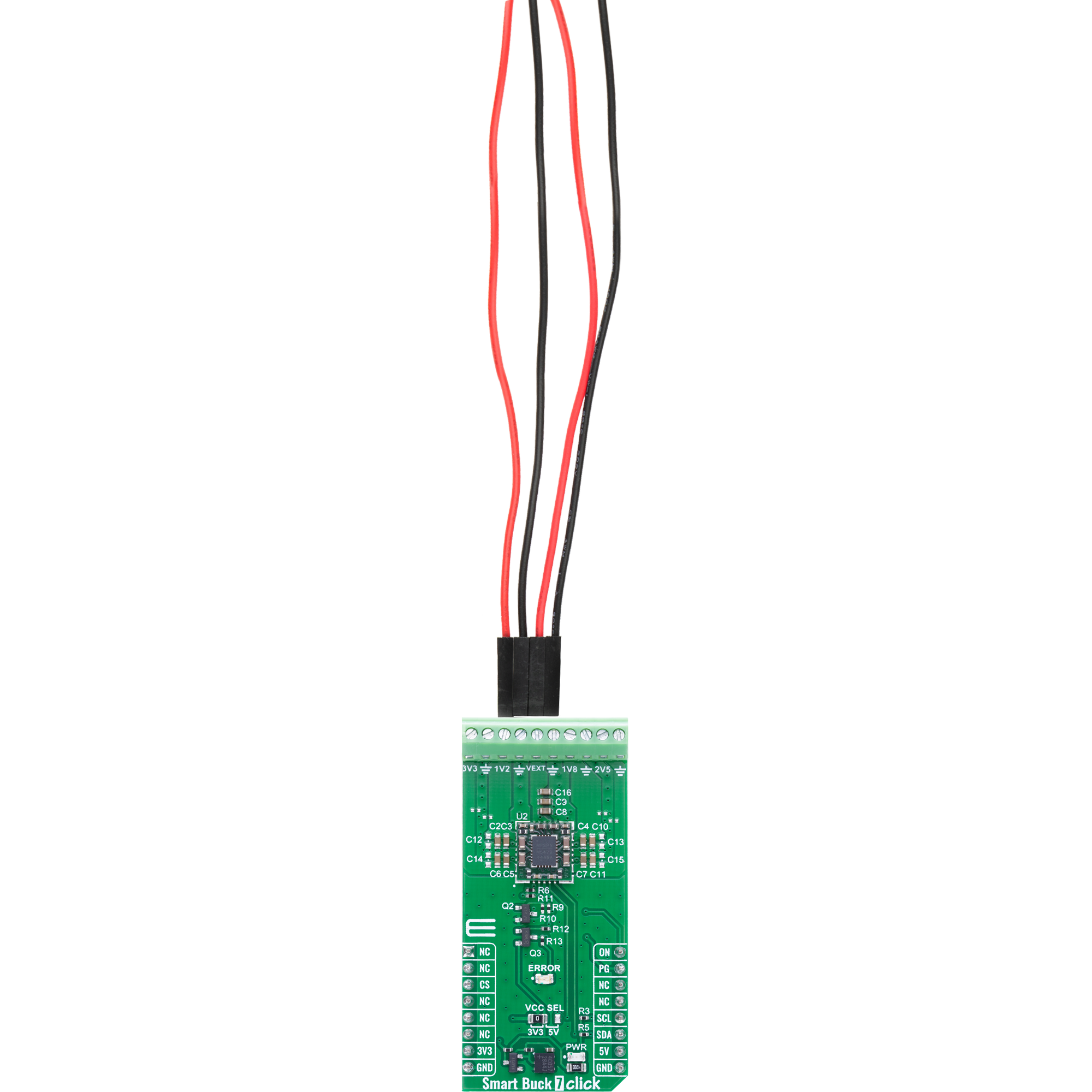
Smart Buck 7 Click
Dev. board
Nucleo 64 with STM32G474RE MCU
Compiler
NECTO Studio
MCU
STM32G474RE
Ideal for powering complex embedded systems with multiple voltage domains
A
A
Hardware Overview
How does it work?
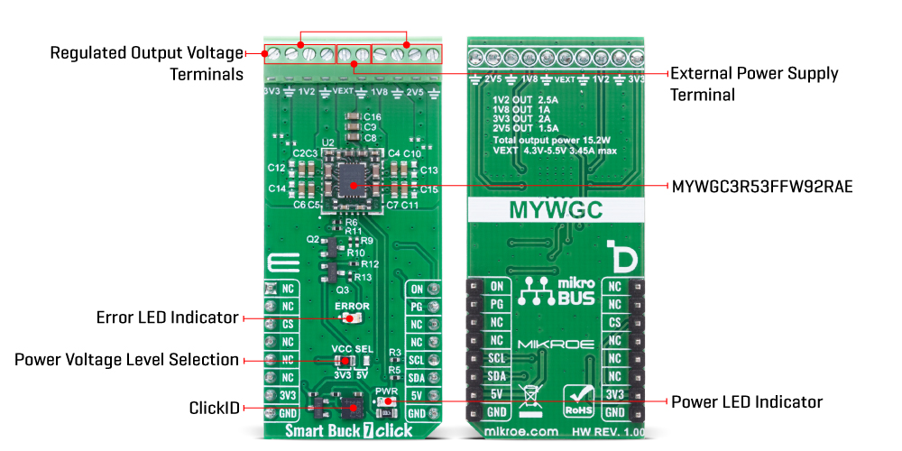
Smart Buck 7 Click is based on the MYWGC3R53FF, a MonoBK™ multi-output DC-DC converter module from Murata, providing multiple precisely regulated output voltages from a single power source. The MYWGC3R53FF accepts an external input voltage ranging from 4.3V to 5.5V applied to the VEXT terminal, with a maximum input current of 3.45A, and uses a fixed-frequency synchronous buck converter topology to derive four independent, fully regulated output rails: 1.2V at 2.5A (Terminal 1V2), 1.8V at 1A (Terminal 1V8), 2.5V at 1.5A (Terminal 2V5), and 3.3V at 2A (Terminal 3V3), delivering a combined total power output of up to 15.2W. This Click board™ is ideal for applications such as powering FPGAs, CPUs, programmable logic, and systems utilizing Distributed Bus Architectures (DBA), as well as complex mixed-voltage platforms commonly found
in datacom and telecom infrastructures. The MYWGC3R53FF interfaces with the host MCU via an I2C-compatible serial interface operating at standard (100kHz) or fast mode (400kHz) clock speeds, enabling control and monitoring of output voltages and status registers. A dedicated ON pin allows for external enable/disable control of the entire power module, supporting power domain management in software-controlled power sequencing scenarios. Additionally, the MYWGC3R53FF features a Power Good (PG pin) output that is also routed to an onboard red LED labeled ERROR, which provides real-time visual indication of any voltage irregularities or faults - when one or more output voltages are out of regulation or disabled. System protection is ensured by an integrated suite of safety mechanisms, including under-voltage lockout
(UVLO) to prevent operation below the minimum input threshold, output short-circuit protection for fault containment, over-current protection (OCP) to prevent damage from excessive load conditions, over-voltage protection (OVP) to guard against feedback failure or load disconnects, and over-temperature protection (OTP) that triggers thermal shutdown to maintain device reliability and system integrity. This Click board™ can operate with either 3.3V or 5V logic voltage levels selected via the VCC SEL jumper. This way, both 3.3V and 5V capable MCUs can use the communication lines properly. Also, this Click board™ comes equipped with a library containing easy-to-use functions and an example code that can be used as a reference for further development.
Features overview
Development board
Nucleo-64 with STM32G474R MCU offers a cost-effective and adaptable platform for developers to explore new ideas and prototype their designs. This board harnesses the versatility of the STM32 microcontroller, enabling users to select the optimal balance of performance and power consumption for their projects. It accommodates the STM32 microcontroller in the LQFP64 package and includes essential components such as a user LED, which doubles as an ARDUINO® signal, alongside user and reset push-buttons, and a 32.768kHz crystal oscillator for precise timing operations. Designed with expansion and flexibility in mind, the Nucleo-64 board features an ARDUINO® Uno V3 expansion connector and ST morpho extension pin
headers, granting complete access to the STM32's I/Os for comprehensive project integration. Power supply options are adaptable, supporting ST-LINK USB VBUS or external power sources, ensuring adaptability in various development environments. The board also has an on-board ST-LINK debugger/programmer with USB re-enumeration capability, simplifying the programming and debugging process. Moreover, the board is designed to simplify advanced development with its external SMPS for efficient Vcore logic supply, support for USB Device full speed or USB SNK/UFP full speed, and built-in cryptographic features, enhancing both the power efficiency and security of projects. Additional connectivity is
provided through dedicated connectors for external SMPS experimentation, a USB connector for the ST-LINK, and a MIPI® debug connector, expanding the possibilities for hardware interfacing and experimentation. Developers will find extensive support through comprehensive free software libraries and examples, courtesy of the STM32Cube MCU Package. This, combined with compatibility with a wide array of Integrated Development Environments (IDEs), including IAR Embedded Workbench®, MDK-ARM, and STM32CubeIDE, ensures a smooth and efficient development experience, allowing users to fully leverage the capabilities of the Nucleo-64 board in their projects.

Microcontroller Overview
MCU Card / MCU

Architecture
ARM Cortex-M4
MCU Memory (KB)
512
Silicon Vendor
STMicroelectronics
Pin count
64
RAM (Bytes)
128k
You complete me!
Accessories
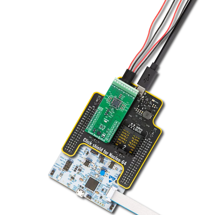
Click Shield for Nucleo-64 comes equipped with two proprietary mikroBUS™ sockets, allowing all the Click board™ devices to be interfaced with the STM32 Nucleo-64 board with no effort. This way, Mikroe allows its users to add any functionality from our ever-growing range of Click boards™, such as WiFi, GSM, GPS, Bluetooth, ZigBee, environmental sensors, LEDs, speech recognition, motor control, movement sensors, and many more. More than 1537 Click boards™, which can be stacked and integrated, are at your disposal. The STM32 Nucleo-64 boards are based on the microcontrollers in 64-pin packages, a 32-bit MCU with an ARM Cortex M4 processor operating at 84MHz, 512Kb Flash, and 96KB SRAM, divided into two regions where the top section represents the ST-Link/V2 debugger and programmer while the bottom section of the board is an actual development board. These boards are controlled and powered conveniently through a USB connection to program and efficiently debug the Nucleo-64 board out of the box, with an additional USB cable connected to the USB mini port on the board. Most of the STM32 microcontroller pins are brought to the IO pins on the left and right edge of the board, which are then connected to two existing mikroBUS™ sockets. This Click Shield also has several switches that perform functions such as selecting the logic levels of analog signals on mikroBUS™ sockets and selecting logic voltage levels of the mikroBUS™ sockets themselves. Besides, the user is offered the possibility of using any Click board™ with the help of existing bidirectional level-shifting voltage translators, regardless of whether the Click board™ operates at a 3.3V or 5V logic voltage level. Once you connect the STM32 Nucleo-64 board with our Click Shield for Nucleo-64, you can access hundreds of Click boards™, working with 3.3V or 5V logic voltage levels.

Used MCU Pins
mikroBUS™ mapper
Take a closer look
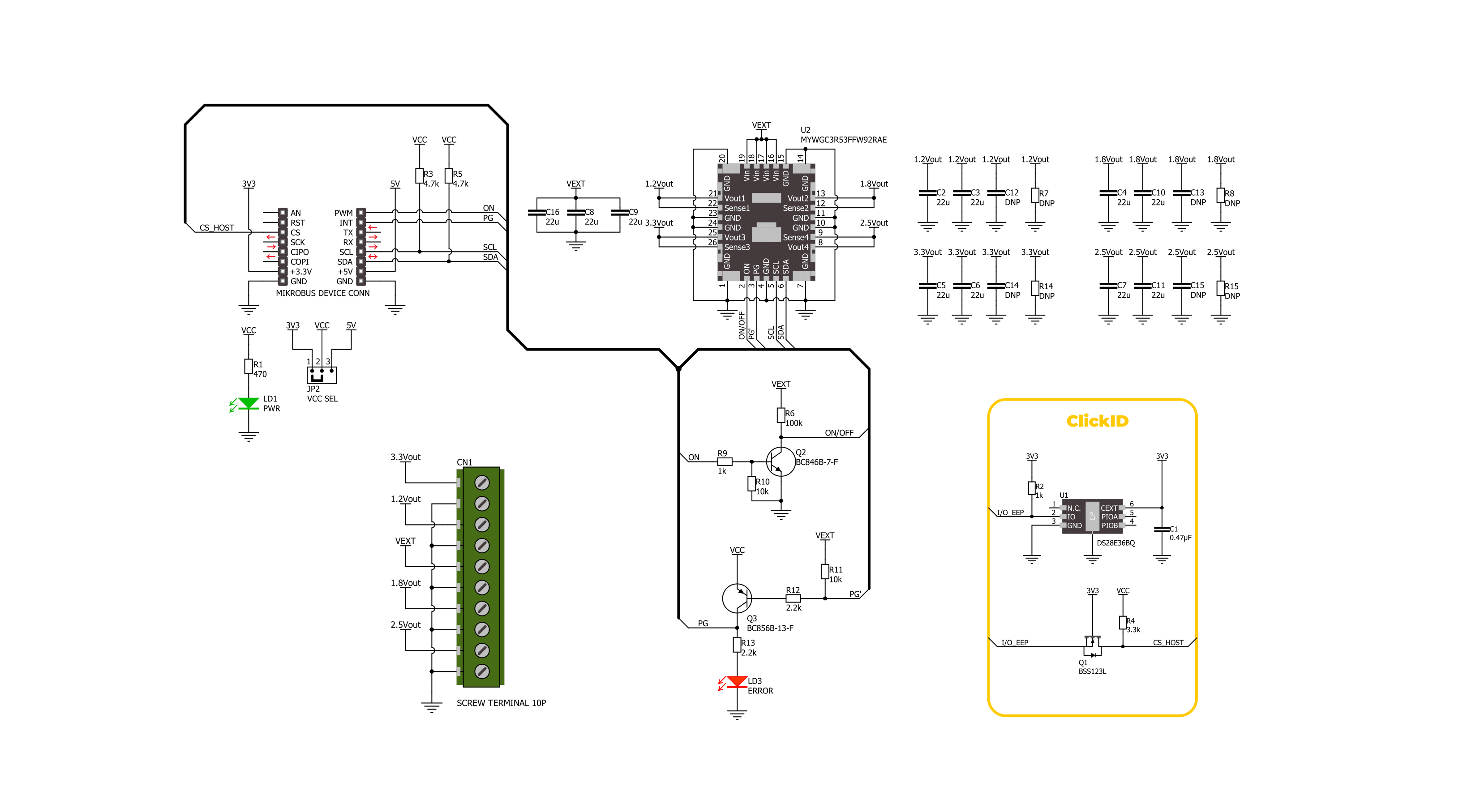
Click board™ Schematic
Step by step
Project assembly
Start by selecting your development board and Click board™. Begin with the Nucleo 64 with STM32G474RE MCU as your development board.


Track your results in real time
Application Output
1. Application Output - In Debug mode, the 'Application Output' window enables real-time data monitoring, offering direct insight into execution results. Ensure proper data display by configuring the environment correctly using the provided tutorial.

2. UART Terminal - Use the UART Terminal to monitor data transmission via a USB to UART converter, allowing direct communication between the Click board™ and your development system. Configure the baud rate and other serial settings according to your project's requirements to ensure proper functionality. For step-by-step setup instructions, refer to the provided tutorial.

3. Plot Output - The Plot feature offers a powerful way to visualize real-time sensor data, enabling trend analysis, debugging, and comparison of multiple data points. To set it up correctly, follow the provided tutorial, which includes a step-by-step example of using the Plot feature to display Click board™ readings. To use the Plot feature in your code, use the function: plot(*insert_graph_name*, variable_name);. This is a general format, and it is up to the user to replace 'insert_graph_name' with the actual graph name and 'variable_name' with the parameter to be displayed.

Software Support
Library Description
Smart Buck 7 Click demo application is developed using the NECTO Studio, ensuring compatibility with mikroSDK's open-source libraries and tools. Designed for plug-and-play implementation and testing, the demo is fully compatible with all development, starter, and mikromedia boards featuring a mikroBUS™ socket.
Example Description
This example demonstrates the use of the Smart Buck 7 Click board. The application cyclically enables different combinations of the four buck converter outputs (1.2V, 1.8V, 2.5V, and 3.3V) and logs which outputs are currently active. It also monitors the PG (Power Good) pin and logs any fault conditions, including undervoltage and over-temperature events.
Key functions:
smartbuck7_cfg_setup- This function initializes Click configuration structure to initial values.smartbuck7_init- This function initializes all necessary pins and peripherals used for this Click board.smartbuck7_default_cfg- This function executes a default configuration of Smart Buck 7 Click board.smartbuck7_get_pg_pin- This function reads the logic level of the PG pin.smartbuck7_enable_buck- This function enables one or more buck regulators by setting their control bits.smartbuck7_disable_buck- This function disables one or more buck regulators by clearing their control bits.
Application Init
Initializes the logger and the Smart Buck 7 Click driver, and applies the default configuration.
Application Task
Cycles through various buck output combinations, logs the enabled outputs, checks the PG pin for fault indication, and logs any detected fault status.
Open Source
Code example
The complete application code and a ready-to-use project are available through the NECTO Studio Package Manager for direct installation in the NECTO Studio. The application code can also be found on the MIKROE GitHub account.
/*!
 * @file main.c
 * @brief Smart Buck 7 Click example
 *
 * # Description
 * This example demonstrates the use of the Smart Buck 7 Click board. The application cyclically enables
 * different combinations of the four buck converter outputs (1.2V, 1.8V, 2.5V, and 3.3V) and logs which
 * outputs are currently active. It also monitors the PG (Power Good) pin and logs any fault conditions,
 * including undervoltage and over-temperature events.
 *
 * The demo application is composed of two sections :
 *
 * ## Application Init
 * Initializes the logger and the Smart Buck 7 Click driver, and applies the default configuration.
 *
 * ## Application Task
 * Cycles through various buck output combinations, logs the enabled outputs,
 * checks the PG pin for fault indication, and logs any detected fault status.
 *
 * @note
 * Ensure all outputs are properly loaded and that the input voltage is within recommended levels
 * to evaluate fault detection reliably.
 *
 * @author Stefan Filipovic
 *
 */

#include "board.h"
#include "log.h"
#include "smartbuck7.h"

static smartbuck7_t smartbuck7;
static log_t logger;

/**
 * @brief Smart Buck 7 display status function.
 * @details This function parses and logs all detected status flags from the Smart Buck 7 Click board
 * including over-temperature and power-good conditions.
 * @param[in] status : Status register structure.
 * See #smartbuck7_status_t object definition for detailed explanation.
 * @return None.
 * @note This function outputs human-readable messages via the logger for each active status flag.
 */
static void smartbuck7_display_status ( smartbuck7_status_t status );

void application_init ( void )
{
    log_cfg_t log_cfg;  /**< Logger config object. */
    smartbuck7_cfg_t smartbuck7_cfg;  /**< Click config object. */

    /**
     * Logger initialization.
     * Default baud rate: 115200
     * Default log level: LOG_LEVEL_DEBUG
     * @note If USB_UART_RX and USB_UART_TX
     * are defined as HAL_PIN_NC, you will
     * need to define them manually for log to work.
     * See @b LOG_MAP_USB_UART macro definition for detailed explanation.
     */
    LOG_MAP_USB_UART( log_cfg );
    log_init( &logger, &log_cfg );
    log_info( &logger, " Application Init " );

    // Click initialization.
    smartbuck7_cfg_setup( &smartbuck7_cfg );
    SMARTBUCK7_MAP_MIKROBUS( smartbuck7_cfg, MIKROBUS_1 );
    if ( I2C_MASTER_ERROR == smartbuck7_init( &smartbuck7, &smartbuck7_cfg ) )
    {
        log_error( &logger, " Communication init." );
        for ( ; ; );
    }

    if ( SMARTBUCK7_ERROR == smartbuck7_default_cfg ( &smartbuck7 ) )
    {
        log_error( &logger, " Default configuration." );
        for ( ; ; );
    }

    log_info( &logger, " Application Task " );
}

void application_task ( void )
{
    smartbuck7_status_t status;
    static uint8_t buck_en = SMARTBUCK7_BUCK_4;
    if ( smartbuck7_get_pg_pin ( &smartbuck7 ) )
    {
        log_printf( &logger, "\r\n Fault indication detected via PG pin!\r\n" );
        if ( SMARTBUCK7_OK == smartbuck7_read_status ( &smartbuck7, &status ) )
        {
            smartbuck7_display_status ( status );
        }
        smartbuck7_clear_status( &smartbuck7 );
    }
    if ( buck_en > SMARTBUCK7_BUCK_ALL )
    {
        if ( SMARTBUCK7_OK == smartbuck7_disable_buck ( &smartbuck7, SMARTBUCK7_BUCK_ALL ) )
        {
            log_printf( &logger, "\r\n Outputs enabled: - NONE -\r\n" );
            buck_en = SMARTBUCK7_BUCK_4;
        }
    }
    else if ( SMARTBUCK7_OK == smartbuck7_enable_buck ( &smartbuck7, buck_en ) )
    {
        log_printf( &logger, "\r\n Outputs enabled: -" );
        if ( buck_en & SMARTBUCK7_BUCK_3 )
        {
            log_printf( &logger, " 3.3V -" );
        }
        if ( buck_en & SMARTBUCK7_BUCK_1 )
        {
            log_printf( &logger, " 1.2V -" );
        }
        if ( buck_en & SMARTBUCK7_BUCK_2 )
        {
            log_printf( &logger, " 1.8V -" );
        }
        if ( buck_en & SMARTBUCK7_BUCK_4 )
        {
            log_printf( &logger, " 2.5V -" );
        }
        log_printf( &logger, "\r\n" );
        buck_en = ( buck_en << 1 ) | SMARTBUCK7_BUCK_4;
    }
    Delay_ms ( 1000 );
    Delay_ms ( 1000 );
}

int main ( void )
{
    /* Do not remove this line or clock might not be set correctly. */
    #ifdef PREINIT_SUPPORTED
    preinit();
    #endif

    application_init( );

    for ( ; ; )
    {
        application_task( );
    }

    return 0;
}

static void smartbuck7_display_status ( smartbuck7_status_t status )
{
    if ( !status.status_1 )
    {
        if ( !( status.status_1 & SMARTBUCK7_STATUS_1_PGBUCK4 ) )
        {
            log_printf ( &logger, " Buck 4 low output voltage\r\n" );
        }
        if ( !( status.status_1 & SMARTBUCK7_STATUS_1_PGBUCK3 ) )
        {
            log_printf ( &logger, " Buck 3 low output voltage\r\n" );
        }
        if ( !( status.status_1 & SMARTBUCK7_STATUS_1_PGBUCK2 ) )
        {
            log_printf ( &logger, " Buck 2 low output voltage\r\n" );
        }
        if ( !( status.status_1 & SMARTBUCK7_STATUS_1_PGBUCK1 ) )
        {
            log_printf ( &logger, " Buck 1 low output voltage\r\n" );
        }
    }
    if ( status.status_2 )
    {
        if ( status.status_1 & SMARTBUCK7_STATUS_2_OTWARNING )
        {
            log_printf ( &logger, " Die temperature early warning\r\n" );
        }
        if ( status.status_1 & SMARTBUCK7_STATUS_2_OTEMPP )
        {
            log_printf ( &logger, " Over temperature fault\r\n" );
        }
    }
}

// ------------------------------------------------------------------------ END
Additional Support
Resources
Category:Buck


