Achieve pinpoint satellite-based positioning with PNT-SG3FS and STM32L496AG
High-precision, multi-constellation GNSS solution for accurate global positioning
Published Jul 22, 2025
Click board™
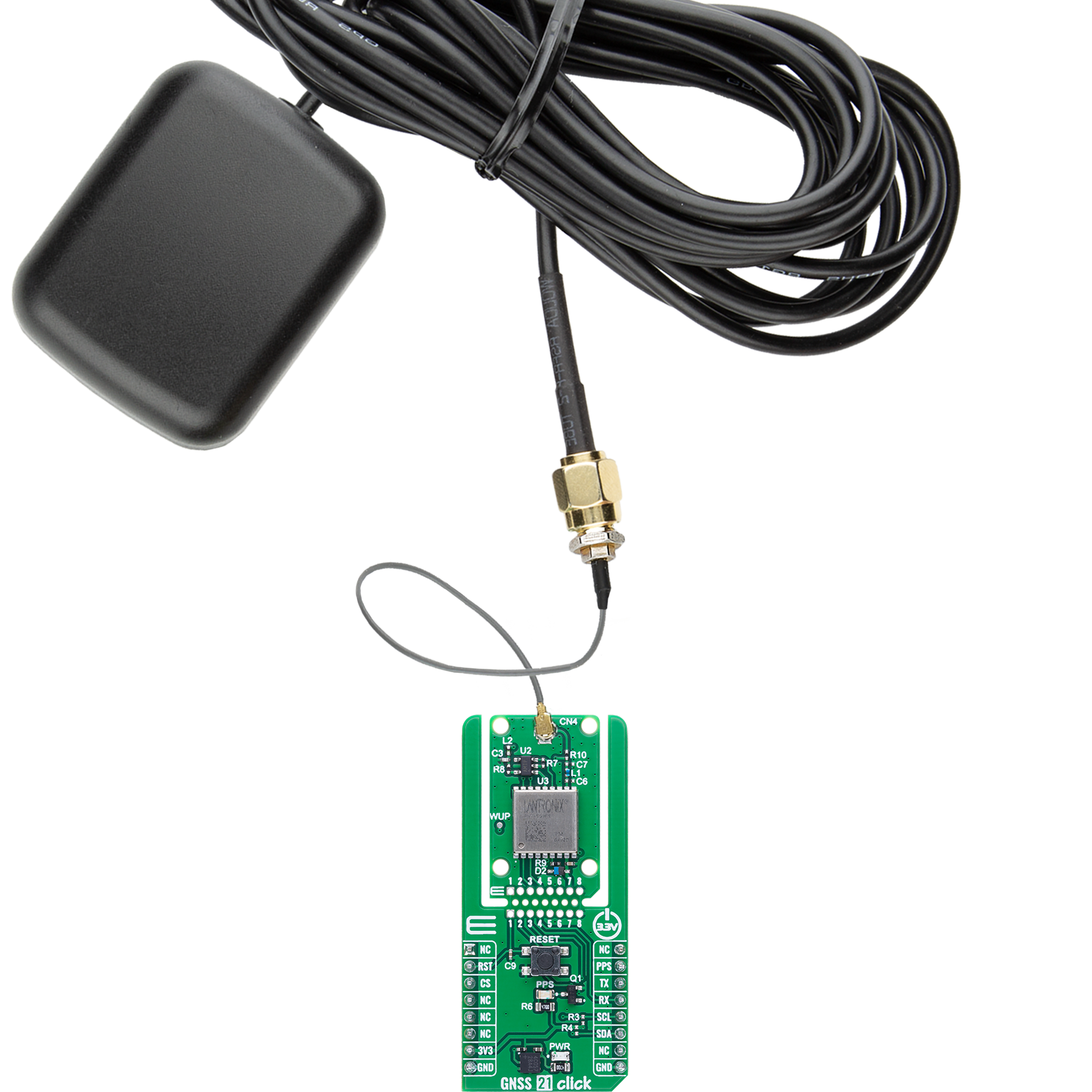
GNSS 21 Click
Dev. board
Discovery kit with STM32L496AG MCU
Compiler
NECTO Studio
MCU
STM32L496AG
Get high-accuracy, multi-constellation GNSS positioning with advanced features like Assisted GNSS and onboard data logging
A
A
Hardware Overview
How does it work?
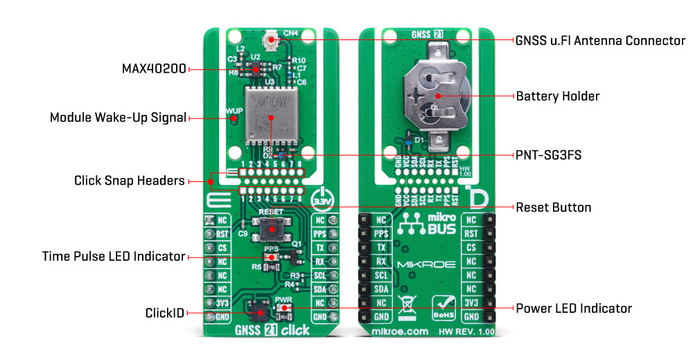
GNSS 21 Click is based on the PNT-SG3FS, a Global Navigation Satellite System (GNSS) module from Lantronix, built around the Teseo III GNSS receiver by STMicroelectronics. Designed to provide reliable and precise positioning, this module supports multi-constellation satellite tracking with the ability to simultaneously monitor up to 32 satellite signals. It covers a wide range of navigation systems, including GPS L1C/A, Galileo E1B/C, BeiDou B1, GLONASS L1OF, QZSS L1C/A, and SBAS L1C/A services such as WAAS, EGNOS, MSAS, and GAGAN. For improved positioning accuracy, the module offers Differential GPS (DGPS) capabilities in compliance with RTCM 10402.3 and supports advanced Assisted GNSS techniques using either local ephemeris prediction or server-based assistance, enabling fast acquisition and minimal Time to First Fix (TTFF), even under challenging conditions. In addition to its core navigation capabilities, the PNT-SG3FS integrates a 16Mb flash memory, allowing for a rich feature set including data logging, geofencing, odometer functionality, firmware updates, and up to 5 days of autonomous assisted GNSS data retention. The onboard temperature-compensated crystal oscillator (TCXO) ensures high stability and accuracy in navigation performance, while the integrated real-time clock (RTC) oscillator supports
clock trimming to optimize timing precision based on the 32.768kHz crystal, making it suitable for time-sensitive applications. The PNT-SG3FS is capable of delivering highly accurate positioning with a circular error probable (CEP) of 1.5 meters, and when used alongside external RTK or PPP client algorithms, it can achieve sub-decimeter accuracy, under 10 centimeters. It boasts a remarkable -163dBm tracking sensitivity and can achieve a cold start TTFF in less than 32 seconds. Certified for compliance with various international standards including the Radio Equipment Directive (RED) 2014/53/EU and several ETSI and EN norms, GNSS 21 Click ensures reliable performance and regulatory approval across a wide range of applications. This Click board™ is designed in a unique format supporting the newly introduced MIKROE feature called "Click Snap." Unlike the standardized version of Click boards, this feature allows the main module area to become movable by breaking the PCB, opening up many new possibilities for implementation. Thanks to the Snap feature, the PNT-SG3FS can operate autonomously by accessing its signals directly on the pins marked 1-8. Additionally, the Snap part includes a specified and fixed screw hole position, enabling users to secure the Snap board in their desired location. The GNSS 21 Click communicates
with the host MCU through a UART interface using the standard UART RX and TX pins. The default communication speed is set at 115200bps, ensuring efficient data exchange. It also provides an I2C interface for communication with a host MCU in the I2C Fast speed mode (400kHz). Still, it must be noted that the I2C interface can only be operated in the peripheral mode. Along with the communication and control pins, this Click board™ also includes a reset pin (RST) and a RESET button, enabling easy module resetting, the timepulse signal indicator (PPS), offering precise time synchronization for applications that require it, module wake-up signal in a form of a test point labeled WUP, and a battery holder for the backup power supply (RAM and RTC backup). The board also features one u.Fl connector for GNSS antenna that MIKROE offers, like the Active GPS antenna combined with an IPEX-SMA cable for flexible and efficient connectivity options. This Click board™ can be operated only with a 3.3V logic voltage level. The board must perform appropriate logic voltage level conversion before using MCUs with different logic levels. It also comes equipped with a library containing functions and example code that can be used as a reference for further development.
Features overview
Development board
The 32L496GDISCOVERY Discovery kit serves as a comprehensive demonstration and development platform for the STM32L496AG microcontroller, featuring an Arm® Cortex®-M4 core. Designed for applications that demand a balance of high performance, advanced graphics, and ultra-low power consumption, this kit enables seamless prototyping for a wide range of embedded solutions. With its innovative energy-efficient
architecture, the STM32L496AG integrates extended RAM and the Chrom-ART Accelerator, enhancing graphics performance while maintaining low power consumption. This makes the kit particularly well-suited for applications involving audio processing, graphical user interfaces, and real-time data acquisition, where energy efficiency is a key requirement. For ease of development, the board includes an onboard ST-LINK/V2-1
debugger/programmer, providing a seamless out-of-the-box experience for loading, debugging, and testing applications without requiring additional hardware. The combination of low power features, enhanced memory capabilities, and built-in debugging tools makes the 32L496GDISCOVERY kit an ideal choice for prototyping advanced embedded systems with state-of-the-art energy efficiency.

Microcontroller Overview
MCU Card / MCU

Architecture
ARM Cortex-M4
MCU Memory (KB)
1024
Silicon Vendor
STMicroelectronics
Pin count
169
RAM (Bytes)
327680
You complete me!
Accessories
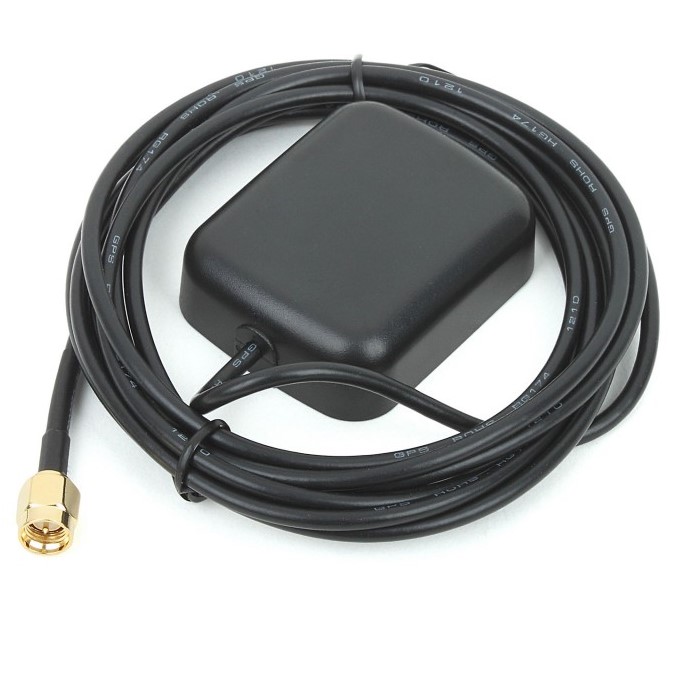
Active GPS antenna is designed to enhance the performance of your GPS and GNSS Click boards™. This external antenna boasts a robust construction, making it ideal for various weather conditions. With a frequency range of 1575.42MHz and a 50Ohm impedance, it ensures reliable signal reception. The antenna delivers a gain of greater than -4dBic within a wide angular range, securing over 75% coverage. The bandwidth of +/- 5MHz further guarantees precise data acquisition. Featuring a Right-Hand Circular Polarization (RHCP), this antenna offers stable signal reception. Its compact dimensions of 48.53915mm and a 2-meter cable make it easy to install. The magnetic antenna type with an SMA male connector ensures a secure and convenient connection. If you require a dependable external antenna for your locator device, our active GPS antenna is the perfect solution.
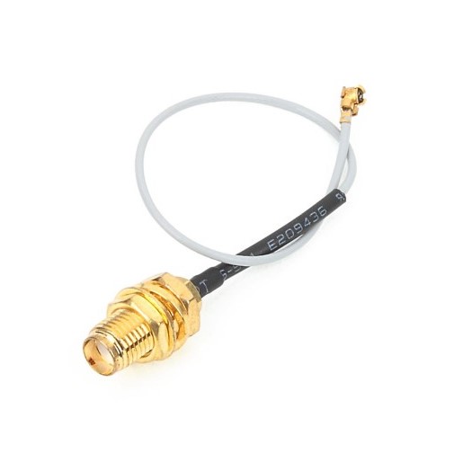
IPEX-SMA cable is a type of RF (radio frequency) cable assembly. "IPEX" refers to the IPEX connector, a miniature coaxial connector commonly used in small electronic devices. "SMA" stands for SubMiniature Version A and is another coaxial connector commonly used in RF applications. An IPEX-SMA cable assembly has an IPEX connector on one end and an SMA connector on the other, allowing it to connect devices or components that use these specific connectors. These cables are often used in applications like WiFi or cellular antennas, GPS modules, and other RF communication systems where a reliable and low-loss connection is required.
Used MCU Pins
mikroBUS™ mapper
Take a closer look
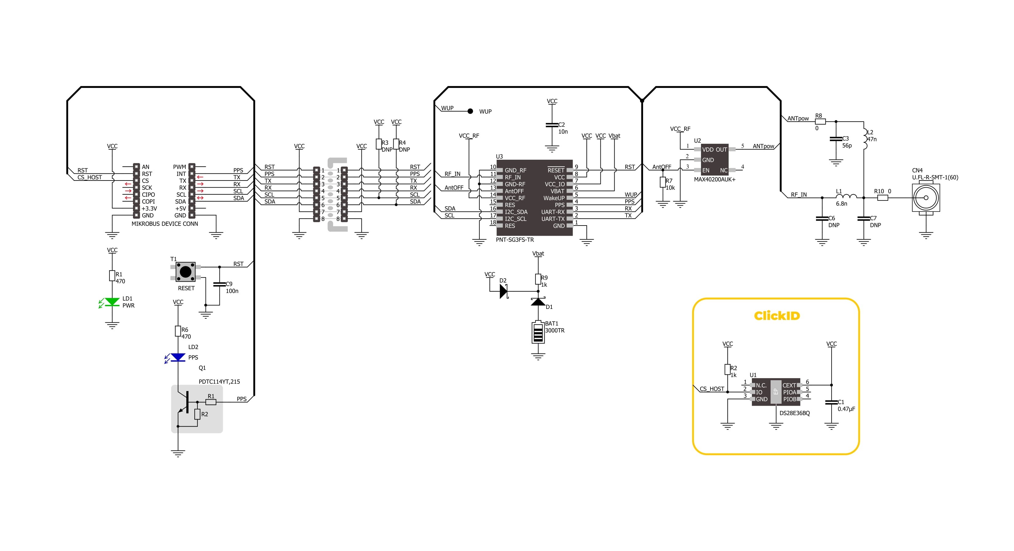
Click board™ Schematic
Step by step
Project assembly

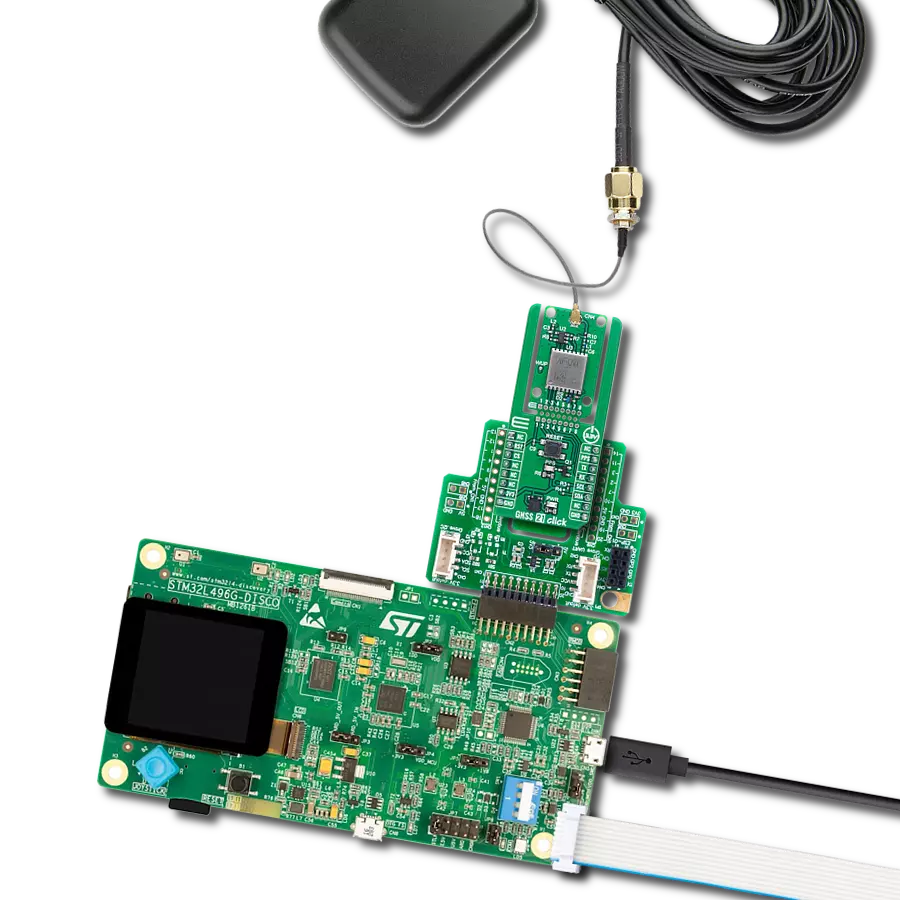
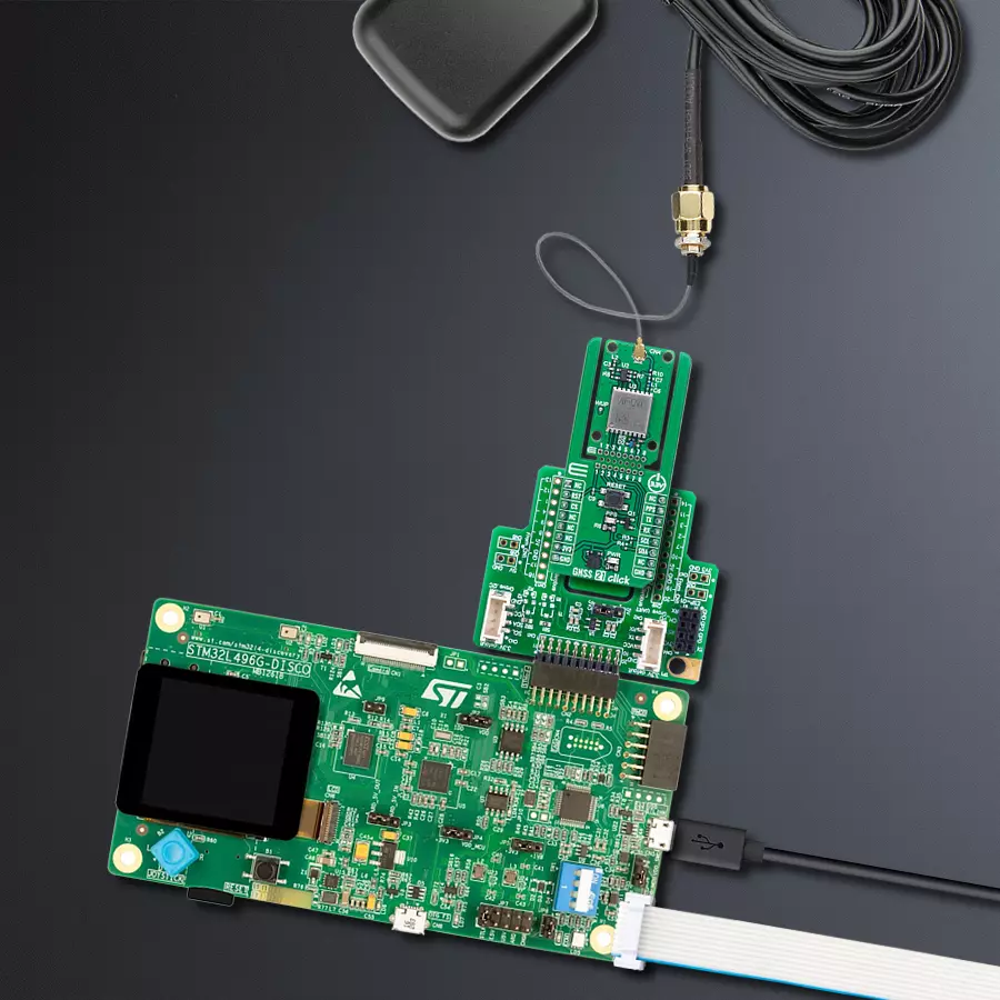
Start by selecting your development board and Click board™. Begin with the Discovery kit with STM32L496AG MCU as your development board.


Track your results in real time
Application Output
1. Application Output - In Debug mode, the 'Application Output' window enables real-time data monitoring, offering direct insight into execution results. Ensure proper data display by configuring the environment correctly using the provided tutorial.

2. UART Terminal - Use the UART Terminal to monitor data transmission via a USB to UART converter, allowing direct communication between the Click board™ and your development system. Configure the baud rate and other serial settings according to your project's requirements to ensure proper functionality. For step-by-step setup instructions, refer to the provided tutorial.

3. Plot Output - The Plot feature offers a powerful way to visualize real-time sensor data, enabling trend analysis, debugging, and comparison of multiple data points. To set it up correctly, follow the provided tutorial, which includes a step-by-step example of using the Plot feature to display Click board™ readings. To use the Plot feature in your code, use the function: plot(*insert_graph_name*, variable_name);. This is a general format, and it is up to the user to replace 'insert_graph_name' with the actual graph name and 'variable_name' with the parameter to be displayed.

Software Support
Library Description
GNSS 21 Click demo application is developed using the NECTO Studio, ensuring compatibility with mikroSDK's open-source libraries and tools. Designed for plug-and-play implementation and testing, the demo is fully compatible with all development, starter, and mikromedia boards featuring a mikroBUS™ socket.
Example Description
This example demonstrates the use of GNSS 21 Click by reading and displaying the GNSS coordinates.
Key functions:
gnss21_cfg_setup- Config Object Initialization function.gnss21_init- Initialization function.gnss21_generic_read- This function reads a desired number of data bytes by using UART or I2C serial interface.gnss21_parse_gga- This function parses the GGA data from the read response buffer.gnss21_reset_device- This function resets the device by toggling the RST pin.
Application Init
Initializes the driver and logger.
Application Task
Reads the received data, parses the NMEA GGA info from it, and once it receives the position fix it will start displaying the coordinates on the USB UART.
Open Source
Code example
The complete application code and a ready-to-use project are available through the NECTO Studio Package Manager for direct installation in the NECTO Studio. The application code can also be found on the MIKROE GitHub account.
/*!
 * @file main.c
 * @brief GNSS 21 Click Example.
 *
 * # Description
 * This example demonstrates the use of GNSS 21 Click by reading and displaying
 * the GNSS coordinates.
 *
 * The demo application is composed of two sections :
 *
 * ## Application Init
 * Initializes the driver and logger.
 *
 * ## Application Task
 * Reads the received data, parses the NMEA GGA info from it, and once it receives
 * the position fix it will start displaying the coordinates on the USB UART.
 *
 * ## Additional Function
 * - static void gnss21_clear_app_buf ( void )
 * - static void gnss21_log_app_buf ( void )
 * - static err_t gnss21_process ( gnss21_t *ctx )
 * - static void gnss21_parser_application ( uint8_t *rsp )
 *
 * @author Stefan Filipovic
 *
 */

#include "board.h"
#include "log.h"
#include "gnss21.h"

// Application buffer size
#define APP_BUFFER_SIZE             500
#define PROCESS_BUFFER_SIZE         200

static gnss21_t gnss21;
static log_t logger;

static uint8_t app_buf[ APP_BUFFER_SIZE + 1 ] = { 0 };
static int32_t app_buf_len = 0;
static uint8_t i2c_data_ready = 0;

/**
 * @brief GNSS 21 clearing application buffer.
 * @details This function clears memory of application buffer and reset its length.
 * @note None.
 */
static void gnss21_clear_app_buf ( void );

/**
 * @brief GNSS 21 log application buffer.
 * @details This function logs data from application buffer to USB UART.
 * @note None.
 */
static void gnss21_log_app_buf ( void );

/**
 * @brief GNSS 21 data reading function.
 * @details This function reads data from device and concatenates data to application buffer.
 * @param[in] ctx : Click context object.
 * See #gnss21_t object definition for detailed explanation.
 * @return @li @c  0 - Read some data.
 *         @li @c -1 - Nothing is read.
 * See #err_t definition for detailed explanation.
 * @note None.
 */
static err_t gnss21_process ( gnss21_t *ctx );

/**
 * @brief GNSS 21 parser application.
 * @details This function logs GNSS data on the USB UART.
 * @param[in] rsp Response buffer.
 * @return None.
 * @note None.
 */
static void gnss21_parser_application ( uint8_t *rsp );

void application_init ( void )
{
    log_cfg_t log_cfg;  /**< Logger config object. */
    gnss21_cfg_t gnss21_cfg;  /**< Click config object. */

    /**
     * Logger initialization.
     * Default baud rate: 115200
     * Default log level: LOG_LEVEL_DEBUG
     * @note If USB_UART_RX and USB_UART_TX
     * are defined as HAL_PIN_NC, you will
     * need to define them manually for log to work.
     * See @b LOG_MAP_USB_UART macro definition for detailed explanation.
     */
    LOG_MAP_USB_UART( log_cfg );
    log_init( &logger, &log_cfg );
    log_info( &logger, " Application Init " );

    // Click initialization.
    gnss21_cfg_setup( &gnss21_cfg );
    GNSS21_MAP_MIKROBUS( gnss21_cfg, MIKROBUS_1 );
    if ( GNSS21_OK != gnss21_init( &gnss21, &gnss21_cfg ) )
    {
        log_error( &logger, " Communication init." );
        for ( ; ; );
    }

    log_info( &logger, " Application Task " );
}

void application_task ( void )
{
    if ( GNSS21_OK == gnss21_process( &gnss21 ) )
    {
        gnss21_parser_application( app_buf );
    }
}

int main ( void )
{
    /* Do not remove this line or clock might not be set correctly. */
    #ifdef PREINIT_SUPPORTED
    preinit();
    #endif

    application_init( );

    for ( ; ; )
    {
        application_task( );
    }

    return 0;
}

static void gnss21_clear_app_buf ( void )
{
    memset( app_buf, 0, app_buf_len );
    app_buf_len = 0;
}

static void gnss21_log_app_buf ( void )
{
    for ( int32_t buf_cnt = 0; buf_cnt < app_buf_len; buf_cnt++ )
    {
        log_printf( &logger, "%c", app_buf[ buf_cnt ] );
    }
}

static err_t gnss21_process ( gnss21_t *ctx )
{
    uint8_t rx_buf[ PROCESS_BUFFER_SIZE ] = { 0 };
    int32_t overflow_bytes = 0;
    int32_t rx_cnt = 0;
    int32_t rx_size = 0;

    if ( ( GNSS21_DRV_SEL_I2C == ctx->drv_sel ) && ( !i2c_data_ready ) )
    {
        uint16_t pps_wait_log_cnt = 0;
        while ( !gnss21_get_pps_pin ( ctx ) )
        {
            if ( ++pps_wait_log_cnt > 5000 )
            {
                log_printf( &logger, " Waiting for the position fix (PPS signal)...\r\n\n" );
                pps_wait_log_cnt = 0;
            }
            Delay_ms ( 1 );
        }
        i2c_data_ready = 1;
        Delay_ms ( 200 );
    }
    rx_size = gnss21_generic_read( ctx, rx_buf, PROCESS_BUFFER_SIZE );
    if ( ( rx_size > 0 ) && ( rx_size <= APP_BUFFER_SIZE ) )
    {
        if ( ( app_buf_len + rx_size ) > APP_BUFFER_SIZE )
        {
            overflow_bytes = ( app_buf_len + rx_size ) - APP_BUFFER_SIZE;
            app_buf_len = APP_BUFFER_SIZE - rx_size;
            memmove ( app_buf, &app_buf[ overflow_bytes ], app_buf_len );
            memset ( &app_buf[ app_buf_len ], 0, overflow_bytes );
        }
        for ( rx_cnt = 0; rx_cnt < rx_size; rx_cnt++ )
        {
            if ( rx_buf[ rx_cnt ] && ( GNSS21_DUMMY != rx_buf[ rx_cnt ] ) )
            {
                app_buf[ app_buf_len++ ] = rx_buf[ rx_cnt ];
            }
        }
        return GNSS21_OK;
    }
    return GNSS21_ERROR;
}

static void gnss21_parser_application ( uint8_t *rsp )
{
    uint8_t element_buf[ 200 ] = { 0 };
    if ( GNSS21_OK == gnss21_parse_gga( rsp, GNSS21_GGA_LATITUDE, element_buf ) )
    {
        static uint8_t wait_for_fix_cnt = 0;
        if ( ( strlen( element_buf ) > 0 ) && ( !strstr ( element_buf, GNSS21_RSP_NO_FIX ) ) )
        {
            log_printf( &logger, "\r\n Latitude: %.2s degrees, %s minutes\r\n", element_buf, &element_buf[ 2 ] );
            memset( element_buf, 0, sizeof( element_buf ) );
            gnss21_parse_gga( rsp, GNSS21_GGA_LONGITUDE, element_buf );
            log_printf( &logger, " Longitude: %.3s degrees, %s minutes\r\n", element_buf, &element_buf[ 3 ] );
            memset( element_buf, 0, sizeof( element_buf ) );
            gnss21_parse_gga( rsp, GNSS21_GGA_ALTITUDE, element_buf );
            log_printf( &logger, " Altitude: %s m\r\n", element_buf );
            wait_for_fix_cnt = 0;
        }
        else
        {
            if ( wait_for_fix_cnt % 5 == 0 )
            {
                log_printf( &logger, " Waiting for the position fix...\r\n\n" );
                wait_for_fix_cnt = 0;
            }
            wait_for_fix_cnt++;
        }
        gnss21_clear_app_buf(  );
        i2c_data_ready = 0;
    }
}

// ------------------------------------------------------------------------ END
Additional Support
Resources
Category:GPS/GNSS