Enable wireless data transfer between devices using Proteus-e (2612011024000) and STM32L476RG
Wireless communication based on the Bluetooth® LE 5.1 technology

Published Dec 24, 2024
Click board™
Proteus-e Click
Dev. board
Nucleo-64 with STM32L476RG MCU
Compiler
NECTO Studio
MCU
STM32L476RG
Secure and low-power Bluetooth® LE 5.1 communication perfect for industrial automation, smart homes, and wireless control systems
A
A
Hardware Overview
How does it work?
Proteus-e Click is based on the 2612011024000, a radio module for wireless communication from Würth Elektronik, designed to enable connectivity between devices such as control systems, remote controls, sensors, and similar applications. Built on Bluetooth® LE 5.1 technology, this module ensures fast, reliable, and secure data transmission in a point-to-point topology, where Proteus-e acts as a Bluetooth® LE "peripheral" device. To establish communication, the counterpart, such as a Proteus-III module or a smartphone, must implement the Bluetooth® LE "central" role, along with the relevant Bluetooth® LE profiles and characteristics that Proteus-e provides. The versatility of Proteus-e Click makes it ideal for a range of applications, including industrial automation systems, remote monitoring of sensors, smart home devices, and wireless control systems that demand low-power operation, secure data transmission, and reliable connectivity. At the core of the 2612011024000 module lies a high-performance Bluetooth® LE chip from the nRF52 series, offering an excellent power efficiency and performance combination. The chip features a 64MHz ARM Cortex-M4 CPU, equipped with 192kB of flash memory and 24kB RAM, and delivers up to 4dBm of output power. This enables Proteus-e to achieve robust wireless communication while maintaining ultra-low power consumption, making it suitable for battery-powered applications. The module's firmware supports an SPP-like Bluetooth® LE profile,
enabling bidirectional data transmission between Proteus-e and other Bluetooth® LE devices that implement the same profile. This data transmission is secured through encrypted and authenticated connections, ensuring data integrity and protection against unauthorized access. This Click board™ is designed in a unique format supporting the newly introduced MIKROE feature called "Click Snap." Unlike the standardized version of Click boards, this feature allows the main module area to become movable by breaking the PCB, opening up many new possibilities for implementation. Thanks to the Snap feature, the 2612011024000 can operate autonomously by accessing its signals directly on the pins marked 1-8. Additionally, the Snap part includes a specified and fixed screw hole position, enabling users to secure the Snap board in their desired location. Communication between the 2612011024000 module and the host MCU is established through a UART interface, using standard UART RX and TX pins, along with hardware flow control pins (CTS/RTS - Clear to Send/Ready to Send) available as test points on the back of the board to ensure efficient and reliable data transfer. The default communication speed is set to 115200bps. In addition to the interface pins, the board features a reset (RST) pin and a RESET button for hard resetting the module when necessary. A blue status LED (ST) clearly indicates the module's operational status, ensuring easy monitoring during use. Furthermore, the EN
pin of the mikroBUS™ socket serves multiple functions. In Transparent mode, selected via the onboard MODE switch, which toggles between Command and Transparent modes, the EN pin functions as an output pin, indicating whether the module is busy with data transmission. In Command mode, the EN pin serves as an input pin with an internal pull-up resistor, used to wake up the UART in cases where it has been previously disabled using the CMD_UARTDISABLE_REQ command. The board also features two dedicated GPIO pins, IO1 and IO2, from the Proteus-e module, which are accessible as test points located on the back of the board, enabling flexible remote control and monitoring of external devices. The Proteus-e module is equipped with an onboard antenna for standard operation. However, this board also includes an external antenna connector (CN1), allowing the integration of an additional antenna to extend radio range when required. In addition to the antenna connector, the board includes SWD pads designed for use with MIKROE's 6-pin Needle Cable, providing an optional flash and debug SWD (Serial Wire Debug) interface functionality. This Click board™ can be operated only with a 3.3V logic voltage level. The board must perform appropriate logic voltage level conversion before using MCUs with different logic levels. It also comes equipped with a library containing functions and example code that can be used as a reference for further development.

Features overview
Development board
Nucleo-64 with STM32L476RG MCU offers a cost-effective and adaptable platform for developers to explore new ideas and prototype their designs. This board harnesses the versatility of the STM32 microcontroller, enabling users to select the optimal balance of performance and power consumption for their projects. It accommodates the STM32 microcontroller in the LQFP64 package and includes essential components such as a user LED, which doubles as an ARDUINO® signal, alongside user and reset push-buttons, and a 32.768kHz crystal oscillator for precise timing operations. Designed with expansion and flexibility in mind, the Nucleo-64 board features an ARDUINO® Uno V3 expansion connector and ST morpho extension pin
headers, granting complete access to the STM32's I/Os for comprehensive project integration. Power supply options are adaptable, supporting ST-LINK USB VBUS or external power sources, ensuring adaptability in various development environments. The board also has an on-board ST-LINK debugger/programmer with USB re-enumeration capability, simplifying the programming and debugging process. Moreover, the board is designed to simplify advanced development with its external SMPS for efficient Vcore logic supply, support for USB Device full speed or USB SNK/UFP full speed, and built-in cryptographic features, enhancing both the power efficiency and security of projects. Additional connectivity is
provided through dedicated connectors for external SMPS experimentation, a USB connector for the ST-LINK, and a MIPI® debug connector, expanding the possibilities for hardware interfacing and experimentation. Developers will find extensive support through comprehensive free software libraries and examples, courtesy of the STM32Cube MCU Package. This, combined with compatibility with a wide array of Integrated Development Environments (IDEs), including IAR Embedded Workbench®, MDK-ARM, and STM32CubeIDE, ensures a smooth and efficient development experience, allowing users to fully leverage the capabilities of the Nucleo-64 board in their projects.

Microcontroller Overview
MCU Card / MCU

Architecture
ARM Cortex-M4
MCU Memory (KB)
1024
Silicon Vendor
STMicroelectronics
Pin count
64
RAM (Bytes)
131072
You complete me!
Accessories
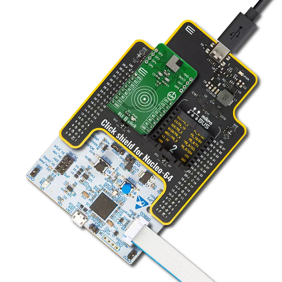
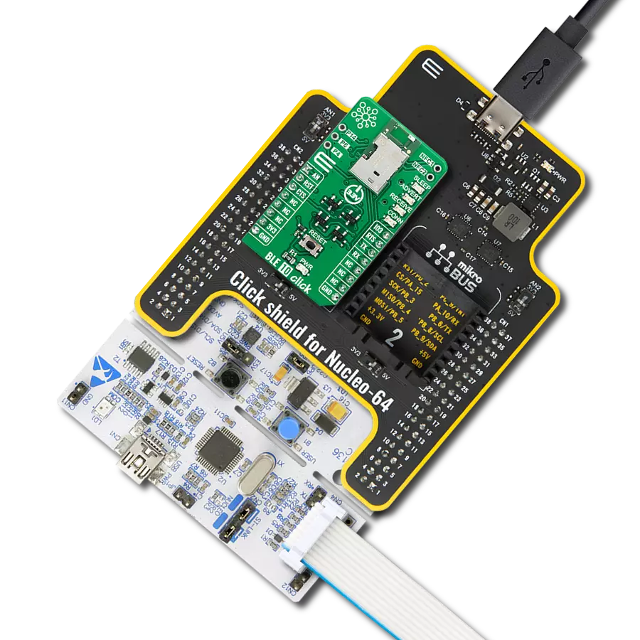
Click Shield for Nucleo-64 comes equipped with two proprietary mikroBUS™ sockets, allowing all the Click board™ devices to be interfaced with the STM32 Nucleo-64 board with no effort. This way, Mikroe allows its users to add any functionality from our ever-growing range of Click boards™, such as WiFi, GSM, GPS, Bluetooth, ZigBee, environmental sensors, LEDs, speech recognition, motor control, movement sensors, and many more. More than 1537 Click boards™, which can be stacked and integrated, are at your disposal. The STM32 Nucleo-64 boards are based on the microcontrollers in 64-pin packages, a 32-bit MCU with an ARM Cortex M4 processor operating at 84MHz, 512Kb Flash, and 96KB SRAM, divided into two regions where the top section represents the ST-Link/V2 debugger and programmer while the bottom section of the board is an actual development board. These boards are controlled and powered conveniently through a USB connection to program and efficiently debug the Nucleo-64 board out of the box, with an additional USB cable connected to the USB mini port on the board. Most of the STM32 microcontroller pins are brought to the IO pins on the left and right edge of the board, which are then connected to two existing mikroBUS™ sockets. This Click Shield also has several switches that perform functions such as selecting the logic levels of analog signals on mikroBUS™ sockets and selecting logic voltage levels of the mikroBUS™ sockets themselves. Besides, the user is offered the possibility of using any Click board™ with the help of existing bidirectional level-shifting voltage translators, regardless of whether the Click board™ operates at a 3.3V or 5V logic voltage level. Once you connect the STM32 Nucleo-64 board with our Click Shield for Nucleo-64, you can access hundreds of Click boards™, working with 3.3V or 5V logic voltage levels.

Used MCU Pins
mikroBUS™ mapper
Take a closer look
Click board™ Schematic

Step by step
Project assembly
Start by selecting your development board and Click board™. Begin with the Nucleo-64 with STM32L476RG MCU as your development board.


Track your results in real time
Application Output
1. Application Output - In Debug mode, the 'Application Output' window enables real-time data monitoring, offering direct insight into execution results. Ensure proper data display by configuring the environment correctly using the provided tutorial.

2. UART Terminal - Use the UART Terminal to monitor data transmission via a USB to UART converter, allowing direct communication between the Click board™ and your development system. Configure the baud rate and other serial settings according to your project's requirements to ensure proper functionality. For step-by-step setup instructions, refer to the provided tutorial.

3. Plot Output - The Plot feature offers a powerful way to visualize real-time sensor data, enabling trend analysis, debugging, and comparison of multiple data points. To set it up correctly, follow the provided tutorial, which includes a step-by-step example of using the Plot feature to display Click board™ readings. To use the Plot feature in your code, use the function: plot(*insert_graph_name*, variable_name);. This is a general format, and it is up to the user to replace 'insert_graph_name' with the actual graph name and 'variable_name' with the parameter to be displayed.

Software Support
Library Description
This library contains API for Proteus-e Click driver.
Key functions:
proteuse_send_cmd- This function sends a desired command packet from the click context object.proteuse_read_event- This function reads an event packet from the ring buffer and stores it in the click context object.proteuse_get_user_setting- This function reads data from the desired user settings index and stores it in the click context event packet object.
Open Source
Code example
The complete application code and a ready-to-use project are available through the NECTO Studio Package Manager for direct installation in the NECTO Studio. The application code can also be found on the MIKROE GitHub account.
/*!
* @file main.c
* @brief Proteus-e Click Example.
*
* # Description
* This example demonstrates the use of Proteus-e Click board by processing data
* from a connected BT device.
*
* The demo application is composed of two sections :
*
* ## Application Init
* Initializes the driver, resets and configures the Click board, and reads the device info.
*
* ## Application Task
* Reads and parses all the received event packets and displays them the USB UART.
* All incoming data messages received from the connected device will be echoed back.
*
* ## Additional Function
* - static err_t proteuse_parse_cnf ( proteuse_t *ctx )
* - static err_t proteuse_parse_rsp ( proteuse_t *ctx )
* - static err_t proteuse_parse_ind ( proteuse_t *ctx )
* - static err_t proteuse_parse_event ( proteuse_t *ctx )
*
* @note
* We recommend using the WE Bluetooth LE Terminal smartphone application for the test.
*
* @author Stefan Filipovic
*
*/
#include "board.h"
#include "log.h"
#include "proteuse.h"
// BT device name.
#define DEVICE_NAME "Proteus-e Click"
static proteuse_t proteuse;
static log_t logger;
/**
* @brief Proteus-e parse cnf function.
* @details This function parses all received confirmation packets and displays them on the USB UART.
* @param[in] ctx : Click context object.
* See #proteuse_t object definition for detailed explanation.
* @return @li @c 0 - Packet parsed successfully,
* @li @c 1 - Error.
* See #err_t definition for detailed explanation.
* @note None.
*/
static err_t proteuse_parse_cnf ( proteuse_t *ctx );
/**
* @brief Proteus-e parse ind function.
* @details This function parses all received response packets and displays them on the USB UART.
* @param[in] ctx : Click context object.
* See #proteuse_t object definition for detailed explanation.
* @return @li @c 0 - Packet parsed successfully,
* @li @c 1 - Error.
* See #err_t definition for detailed explanation.
* @note None.
*/
static err_t proteuse_parse_rsp ( proteuse_t *ctx );
/**
* @brief Proteus-e parse ind function.
* @details This function parses all received indication packets and displays them on the USB UART.
* @param[in] ctx : Click context object.
* See #proteuse_t object definition for detailed explanation.
* @return @li @c 0 - Packet parsed successfully,
* @li @c 1 - Error.
* See #err_t definition for detailed explanation.
* @note None.
*/
static err_t proteuse_parse_ind ( proteuse_t *ctx );
/**
* @brief Proteus-e parse event function.
* @details This function parses all received packets and displays them on the USB UART.
* @param[in] ctx : Click context object.
* See #proteuse_t object definition for detailed explanation.
* @return @li @c 0 - Packet parsed successfully,
* @li @c 1 - Error.
* See #err_t definition for detailed explanation.
* @note None.
*/
static err_t proteuse_parse_event ( proteuse_t *ctx );
void application_init ( void )
{
log_cfg_t log_cfg; /**< Logger config object. */
proteuse_cfg_t proteuse_cfg; /**< Click config object. */
/**
* Logger initialization.
* Default baud rate: 115200
* Default log level: LOG_LEVEL_DEBUG
* @note If USB_UART_RX and USB_UART_TX
* are defined as HAL_PIN_NC, you will
* need to define them manually for log to work.
* See @b LOG_MAP_USB_UART macro definition for detailed explanation.
*/
LOG_MAP_USB_UART( log_cfg );
log_init( &logger, &log_cfg );
log_info( &logger, " Application Init " );
// Click initialization.
proteuse_cfg_setup( &proteuse_cfg );
PROTEUSE_MAP_MIKROBUS( proteuse_cfg, MIKROBUS_1 );
if ( UART_ERROR == proteuse_init( &proteuse, &proteuse_cfg ) )
{
log_error( &logger, " Communication init." );
for ( ; ; );
}
if ( PROTEUSE_ERROR == proteuse_default_cfg ( &proteuse ) )
{
log_error( &logger, " Default configuration." );
for ( ; ; );
}
log_printf( &logger, ">> Get device info.\r\n" );
if ( PROTEUSE_OK == proteuse_get_user_setting ( &proteuse, PROTEUSE_SET_IDX_FS_DEVICE_INFO ) )
{
log_printf( &logger, " < OS version: 0x%.2X%.2X\r\n",
( uint16_t ) proteuse.evt_pkt.payload[ 2 ],
( uint16_t ) proteuse.evt_pkt.payload[ 1 ] );
log_printf( &logger, " Build code: 0x%.2X%.2X%.2X%.2X\r\n",
( uint16_t ) proteuse.evt_pkt.payload[ 6 ],
( uint16_t ) proteuse.evt_pkt.payload[ 5 ],
( uint16_t ) proteuse.evt_pkt.payload[ 4 ],
( uint16_t ) proteuse.evt_pkt.payload[ 3 ] );
log_printf( &logger, " Package variant: 0x%.2X%.2X\r\n",
( uint16_t ) proteuse.evt_pkt.payload[ 8 ],
( uint16_t ) proteuse.evt_pkt.payload[ 7 ] );
log_printf( &logger, " Chip ID: 0x%.2X%.2X%.2X%.2X\r\n\n",
( uint16_t ) proteuse.evt_pkt.payload[ 12 ],
( uint16_t ) proteuse.evt_pkt.payload[ 11 ],
( uint16_t ) proteuse.evt_pkt.payload[ 10 ],
( uint16_t ) proteuse.evt_pkt.payload[ 9 ] );
}
log_printf( &logger, ">> Get FW version.\r\n" );
if ( PROTEUSE_OK == proteuse_get_user_setting ( &proteuse, PROTEUSE_SET_IDX_FS_FW_VERSION ) )
{
log_printf( &logger, " < FW version: %u.%u.%u\r\n\n",
( uint16_t ) proteuse.evt_pkt.payload[ 3 ],
( uint16_t ) proteuse.evt_pkt.payload[ 2 ],
( uint16_t ) proteuse.evt_pkt.payload[ 1 ] );
}
log_printf( &logger, ">> Get BT MAC.\r\n" );
if ( PROTEUSE_OK == proteuse_get_user_setting ( &proteuse, PROTEUSE_SET_IDX_FS_BTMAC ) )
{
log_printf( &logger, " < BT MAC: %.2X:%.2X:%.2X:%.2X:%.2X:%.2X\r\n\n",
( uint16_t ) proteuse.evt_pkt.payload[ 6 ],
( uint16_t ) proteuse.evt_pkt.payload[ 5 ],
( uint16_t ) proteuse.evt_pkt.payload[ 4 ],
( uint16_t ) proteuse.evt_pkt.payload[ 3 ],
( uint16_t ) proteuse.evt_pkt.payload[ 2 ],
( uint16_t ) proteuse.evt_pkt.payload[ 1 ] );
}
log_printf( &logger, ">> Set device name to \"%s\".\r\n", ( char * ) DEVICE_NAME );
if ( PROTEUSE_OK == proteuse_set_user_setting ( &proteuse, PROTEUSE_SET_IDX_RF_DEVICE_NAME,
DEVICE_NAME, strlen ( DEVICE_NAME ) ) )
{
log_printf( &logger, " < Request received, settings set successfully\r\n\n" );
}
log_printf( &logger, ">> Get device name.\r\n" );
if ( PROTEUSE_OK == proteuse_get_user_setting ( &proteuse, PROTEUSE_SET_IDX_RF_DEVICE_NAME ) )
{
log_printf( &logger, " < Device name: \"%s\"\r\n\n", &proteuse.evt_pkt.payload[ 1 ] );
}
log_info( &logger, " Application Task " );
}
void application_task ( void )
{
if ( PROTEUSE_OK == proteuse_read_event ( &proteuse ) )
{
proteuse_parse_event ( &proteuse );
}
}
int main ( void )
{
/* Do not remove this line or clock might not be set correctly. */
#ifdef PREINIT_SUPPORTED
preinit();
#endif
application_init( );
for ( ; ; )
{
application_task( );
}
return 0;
}
static err_t proteuse_parse_cnf ( proteuse_t *ctx )
{
err_t error_flag = PROTEUSE_OK;
uint16_t byte_cnt = 0;
if ( PROTEUSE_CMD_TYPE_CNF == ( ctx->evt_pkt.cmd & PROTEUSE_CMD_TYPE_MASK ) )
{
// Parse confirmation packet
switch ( ctx->evt_pkt.cmd )
{
case PROTEUSE_CMD_CNF_GET_STATE:
{
log_printf( &logger, " < GET_STATE_CNF -> Role: 0x%.2X, Actions: 0x%.2X",
( uint16_t ) ctx->evt_pkt.payload[ 0 ], ( uint16_t ) ctx->evt_pkt.payload[ 1 ] );
if ( ctx->evt_pkt.payload_len > 2 )
{
log_printf( &logger, "\r\n More info: " );
for ( byte_cnt = 2; byte_cnt < ctx->evt_pkt.payload_len; byte_cnt++ )
{
log_printf( &logger, "0x%.2X ", ( uint16_t ) ctx->evt_pkt.payload[ byte_cnt ] );
}
}
break;
}
case PROTEUSE_CMD_CNF_GET:
{
log_printf( &logger, " < GET_CNF -> " );
switch ( ctx->evt_pkt.payload[ 0 ] )
{
case PROTEUSE_CNF_GET_STATUS_OK:
{
log_printf( &logger, "Request received, read out of setting successful" );
break;
}
case PROTEUSE_CNF_GET_STATUS_FAILED:
{
log_printf( &logger, "Operation failed" );
break;
}
case PROTEUSE_CNF_GET_STATUS_NOT_PERMITTED:
{
log_printf( &logger, "Operation not permitted" );
break;
}
default:
{
log_printf( &logger, "Unknown status: 0x%.2X", ( uint16_t ) ctx->evt_pkt.payload[ 0 ] );
break;
}
}
if ( ctx->evt_pkt.payload_len > 1 )
{
log_printf( &logger, "\r\n Setting: " );
for ( byte_cnt = 1; byte_cnt < ctx->evt_pkt.payload_len; byte_cnt++ )
{
log_printf( &logger, "0x%.2X ", ( uint16_t ) ctx->evt_pkt.payload[ byte_cnt ] );
}
}
break;
}
case PROTEUSE_CMD_CNF_DATA:
{
log_printf( &logger, " < DATA_CNF -> " );
switch ( ctx->evt_pkt.payload[ 0 ] )
{
case PROTEUSE_CNF_DATA_STATUS_OK:
{
log_printf( &logger, "Request received, will send data now" );
break;
}
case PROTEUSE_CNF_DATA_STATUS_FAILED:
{
log_printf( &logger, "Operation failed" );
break;
}
case PROTEUSE_CNF_DATA_STATUS_NOT_PERMITTED:
{
log_printf( &logger, "Operation not permitted" );
break;
}
default:
{
log_printf( &logger, "Unknown status: 0x%.2X", ( uint16_t ) ctx->evt_pkt.payload[ 0 ] );
break;
}
}
break;
}
default:
{
log_printf( &logger, " < CMD_CNF 0x%.2X -> ", ( uint16_t ) ctx->evt_pkt.cmd );
for ( byte_cnt = 0; byte_cnt < ctx->evt_pkt.payload_len; byte_cnt++ )
{
log_printf( &logger, "0x%.2X ", ( uint16_t ) ctx->evt_pkt.payload[ byte_cnt ] );
}
break;
}
}
log_printf( &logger, "\r\n\n" );
}
else
{
// Wrong packet type
error_flag |= PROTEUSE_ERROR;
}
return error_flag;
}
static err_t proteuse_parse_rsp ( proteuse_t *ctx )
{
err_t error_flag = PROTEUSE_OK;
if ( PROTEUSE_CMD_TYPE_RSP == ( ctx->evt_pkt.cmd & PROTEUSE_CMD_TYPE_MASK ) )
{
// Parse response packet
if ( PROTEUSE_CMD_RSP_TX_COMPLETE == ctx->evt_pkt.cmd )
{
log_printf( &logger, " < TX_COMPLETE_IND -> " );
if ( ctx->evt_pkt.payload[ 0 ] )
{
log_printf( &logger, "Data transmission failed" );
}
else
{
log_printf( &logger, "Data transmitted successfully" );
}
}
else if ( PROTEUSE_CMD_RSP_CHANNEL_OPEN == ctx->evt_pkt.cmd )
{
log_printf( &logger, " < CHANNEL_OPEN_RSP -> " );
if ( ctx->evt_pkt.payload[ 0 ] )
{
log_printf( &logger, "Failed" );
}
else
{
log_printf( &logger, "MAC: %.2X:%.2X:%.2X:%.2X:%.2X:%.2X, MPS: %u",
( uint16_t ) ctx->evt_pkt.payload[ 6 ], ( uint16_t ) ctx->evt_pkt.payload[ 5 ],
( uint16_t ) ctx->evt_pkt.payload[ 4 ], ( uint16_t ) ctx->evt_pkt.payload[ 3 ],
( uint16_t ) ctx->evt_pkt.payload[ 2 ], ( uint16_t ) ctx->evt_pkt.payload[ 1 ],
( uint16_t ) ctx->evt_pkt.payload[ 7 ] );
}
}
else
{
log_printf( &logger, " < UNKNOWN_RSP 0x%.2X", ( uint16_t ) ctx->evt_pkt.cmd );
}
log_printf( &logger, "\r\n\n" );
}
else
{
// Wrong packet type
error_flag |= PROTEUSE_ERROR;
}
return error_flag;
}
static err_t proteuse_parse_ind ( proteuse_t *ctx )
{
err_t error_flag = PROTEUSE_OK;
uint16_t byte_cnt = 0;
if ( PROTEUSE_CMD_TYPE_IND == ( ctx->evt_pkt.cmd & PROTEUSE_CMD_TYPE_MASK ) )
{
// Parse indication packet
switch ( ctx->evt_pkt.cmd )
{
case PROTEUSE_CMD_IND_SLEEP:
{
log_printf( &logger, " < SLEEP_IND -> Advertising timeout detected, will go to sleep now" );
break;
}
case PROTEUSE_CMD_IND_DATA:
{
log_printf( &logger, " < DATA_IND -> " );
log_printf( &logger, "MAC: %.2X:%.2X:%.2X:%.2X:%.2X:%.2X, RSSI: %d\r\n",
( uint16_t ) ctx->evt_pkt.payload[ 5 ], ( uint16_t ) ctx->evt_pkt.payload[ 4 ],
( uint16_t ) ctx->evt_pkt.payload[ 3 ], ( uint16_t ) ctx->evt_pkt.payload[ 2 ],
( uint16_t ) ctx->evt_pkt.payload[ 1 ], ( uint16_t ) ctx->evt_pkt.payload[ 0 ],
( int16_t ) ( ( int8_t ) ctx->evt_pkt.payload[ 6 ] ) );
log_printf( &logger, " Data (HEX): " );
for ( byte_cnt = 7; byte_cnt < ctx->evt_pkt.payload_len; byte_cnt++ )
{
log_printf( &logger, "0x%.2X ", ( uint16_t ) ctx->evt_pkt.payload[ byte_cnt ] );
}
ctx->evt_pkt.payload[ ctx->evt_pkt.payload_len ] = 0;
log_printf( &logger, "\r\n Data (STR): %s", &ctx->evt_pkt.payload[ 7 ] );
log_printf( &logger, "\r\n\n>> Echo back the received message." );
ctx->cmd_pkt.cmd = PROTEUSE_CMD_REQ_DATA;
ctx->cmd_pkt.payload_len = ctx->evt_pkt.payload_len - 7;
memcpy ( &ctx->cmd_pkt.payload[ 0 ], &ctx->evt_pkt.payload[ 7 ], ctx->evt_pkt.payload_len - 7 );
proteuse_send_cmd ( ctx );
break;
}
case PROTEUSE_CMD_IND_CONNECT:
{
log_printf( &logger, " < CONNECT_IND -> " );
if ( ctx->evt_pkt.payload[ 0 ] )
{
log_printf( &logger, "Connection failed, e.g. due to a timeout" );
}
else
{
log_printf( &logger, "MAC: %.2X:%.2X:%.2X:%.2X:%.2X:%.2X",
( uint16_t ) ctx->evt_pkt.payload[ 6 ], ( uint16_t ) ctx->evt_pkt.payload[ 5 ],
( uint16_t ) ctx->evt_pkt.payload[ 4 ], ( uint16_t ) ctx->evt_pkt.payload[ 3 ],
( uint16_t ) ctx->evt_pkt.payload[ 2 ], ( uint16_t ) ctx->evt_pkt.payload[ 1 ] );
}
break;
}
case PROTEUSE_CMD_IND_DISCONNECT:
{
log_printf( &logger, " < DISCONNECT_IND -> " );
switch ( ctx->evt_pkt.payload[ 0 ] )
{
case PROTEUSE_IND_DISC_REASON_TIMEOUT:
{
log_printf( &logger, "Connection timeout" );
break;
}
case PROTEUSE_IND_DISC_REASON_USER_TERM:
{
log_printf( &logger, "User terminated connection" );
break;
}
case PROTEUSE_IND_DISC_REASON_HOST_TERM:
{
log_printf( &logger, "Host terminated connection" );
break;
}
case PROTEUSE_IND_DISC_REASON_CONN_INTERVAL:
{
log_printf( &logger, "Connection interval unacceptable" );
break;
}
case PROTEUSE_IND_DISC_REASON_MIC_FAILURE:
{
log_printf( &logger, "Connection terminated due to MIC failure" );
break;
}
case PROTEUSE_IND_DISC_REASON_SETUP_FAILED:
{
log_printf( &logger, "Connection setup failed" );
break;
}
default:
{
log_printf( &logger, "Unknown reason: 0x%.2X", ( uint16_t ) ctx->evt_pkt.payload[ 0 ] );
break;
}
}
break;
}
case PROTEUSE_CMD_IND_SECURITY:
{
log_printf( &logger, " < SECURITY_IND -> " );
switch ( ctx->evt_pkt.payload[ 0 ] )
{
case PROTEUSE_IND_SEC_STATUS_RE_BONDED:
{
log_printf( &logger, "Encrypted link to previously bonded device established\r\n" );
break;
}
case PROTEUSE_IND_SEC_STATUS_BONDED:
{
log_printf( &logger, "Bonding successful, encrypted link established\r\n" );
break;
}
case PROTEUSE_IND_SEC_STATUS_PAIRED:
{
log_printf( &logger, "No bonding, pairing successful, encrypted link established\r\n" );
break;
}
default:
{
log_printf( &logger, "Unknown status: 0x%.2X", ( uint16_t ) ctx->evt_pkt.payload[ 0 ] );
break;
}
}
log_printf( &logger, " MAC: %.2X:%.2X:%.2X:%.2X:%.2X:%.2X",
( uint16_t ) ctx->evt_pkt.payload[ 6 ], ( uint16_t ) ctx->evt_pkt.payload[ 5 ],
( uint16_t ) ctx->evt_pkt.payload[ 4 ], ( uint16_t ) ctx->evt_pkt.payload[ 3 ],
( uint16_t ) ctx->evt_pkt.payload[ 2 ], ( uint16_t ) ctx->evt_pkt.payload[ 1 ] );
break;
}
case PROTEUSE_CMD_IND_PHY_UPDATE:
{
log_printf( &logger, " < PHY_UPDATE_IND -> " );
if ( ctx->evt_pkt.payload[ 0 ] )
{
log_printf( &logger, "Unsupported feature of remote device" );
}
else
{
log_printf( &logger, "RX: %uMBit, TX: %uMBit, ",
( uint16_t ) ctx->evt_pkt.payload[ 1 ], ( uint16_t ) ctx->evt_pkt.payload[ 2 ] );
log_printf( &logger, "MAC: %.2X:%.2X:%.2X:%.2X:%.2X:%.2X",
( uint16_t ) ctx->evt_pkt.payload[ 8 ], ( uint16_t ) ctx->evt_pkt.payload[ 7 ],
( uint16_t ) ctx->evt_pkt.payload[ 6 ], ( uint16_t ) ctx->evt_pkt.payload[ 5 ],
( uint16_t ) ctx->evt_pkt.payload[ 4 ], ( uint16_t ) ctx->evt_pkt.payload[ 3 ] );
}
break;
}
case PROTEUSE_CMD_IND_UART_ENABLE:
{
log_printf( &logger, " < UART_ENABLE_IND -> UART has been re-enabled successfully" );
break;
}
case PROTEUSE_CMD_IND_ERROR:
{
log_printf( &logger, " < ERROR_IND -> UART buffer overflow" );
break;
}
default:
{
log_printf( &logger, " < CMD_IND 0x%.2X -> ", ( uint16_t ) ctx->evt_pkt.cmd );
for ( byte_cnt = 0; byte_cnt < ctx->evt_pkt.payload_len; byte_cnt++ )
{
log_printf( &logger, "0x%.2X ", ( uint16_t ) ctx->evt_pkt.payload[ byte_cnt ] );
}
break;
}
}
log_printf( &logger, "\r\n\n" );
}
else
{
// Wrong packet type
error_flag |= PROTEUSE_ERROR;
}
return error_flag;
}
static err_t proteuse_parse_event ( proteuse_t *ctx )
{
err_t error_flag = PROTEUSE_OK;
if ( PROTEUSE_CMD_TYPE_CNF == ( ctx->evt_pkt.cmd & PROTEUSE_CMD_TYPE_MASK ) )
{
error_flag |= proteuse_parse_cnf ( ctx );
}
else if ( PROTEUSE_CMD_TYPE_RSP == ( ctx->evt_pkt.cmd & PROTEUSE_CMD_TYPE_MASK ) )
{
error_flag |= proteuse_parse_rsp ( ctx );
}
else if ( PROTEUSE_CMD_TYPE_IND == ( ctx->evt_pkt.cmd & PROTEUSE_CMD_TYPE_MASK ) )
{
error_flag |= proteuse_parse_ind ( ctx );
}
else
{
// Error packet should not be a command request
error_flag |= PROTEUSE_ERROR;
}
return error_flag;
}
// ------------------------------------------------------------------------ END
Additional Support
Resources
Category:BT/BLE