Bluetooth LE communication for IoT applications with dual-device connectivity based on RYB080I and STM32F103RB
2.4GHz Bluetooth 4.2 and 5.0 Low Energy (LE) solution with an integrated antenna
Published Dec 17, 2024
Click board™
RYB080I Click
Dev. board
Nucleo 64 with STM32F103RB MCU
Compiler
NECTO Studio
MCU
STM32F103RB
Bluetooth LE communication with dual-role connectivity and EMI protection perfect for smart homes, remote monitoring, and indoor positioning in IoT systems
A
A
Hardware Overview
How does it work?
RYB080I Click is based on the RYB080I, a 2.4GHz Bluetooth 4.2/5.0 Low Energy (LE) module from REYAX. Featuring an integrated antenna, this module is designed for seamless connectivity with smartphones and various Bluetooth-enabled devices. This module is based on the TI CC2640R2F ARM® Cortex®-M3 microcontroller, an industry-standard chip known for its efficient performance and reliability, and supports a dual-connection feature, enabling it to maintain simultaneous communication with two Bluetooth devices. It also supports both Host and Client roles, making it highly adaptable for various wireless communication scenarios. With its robust functionality, this Click board™ is ideal for remote monitoring and control applications, smart home systems, and indoor positioning solutions. One of the module's key advantages is the integrated metal cover, which protects against electromagnetic interference (EMI), ensuring stable and reliable operation even in environments with significant signal noise. It operates on the widely
adopted Generic Attribute Profile (GATT), enabling smooth interaction with Bluetooth Low Energy devices. Control and configuration are easily managed using REYAX-developed AT commands, simplifying setup and integration into various projects. Certified under FCC CFR47 Part 15 (US), NCC (Taiwan), and MIC (Japan), the RYB080I meets rigorous international standards, offering compliance and reliability for global applications. This Click board™ is designed in a unique format supporting the newly introduced MIKROE feature called "Click Snap." Unlike the standardized version of Click boards, this feature allows the main sensor area to become movable by breaking the PCB, opening up many new possibilities for implementation. Thanks to the Snap feature, the RYB080I can operate autonomously by accessing its signals directly on the pins marked 1-8. Additionally, the Snap part includes a specified and fixed screw hole position, enabling users to secure the Snap board in their desired location. Regarding the board's connectivity features, this Click board™
uses a UART interface for communication with the host MCU, using standard UART RX and TX pins to exchange AT commands. By default, it communicates at a baud rate of 115200bps. Additionally, unpopulated JTAG header pins provide full support for debugging and programming. This header allows users to use a Joint Test Action Group (JTAG) industry standard for programming and debugging via these JTAG pins. Along with the communication and control pins, this Click board™ also includes a reset pin (RST) and a RESET button, enabling easy module resetting and a six test point that connects to the module general-purpose I/O pins, allowing further customization. This Click board™ can be operated only with a 3.3V logic voltage level. The board must perform appropriate logic voltage level conversion before using MCUs with different logic levels. It also comes equipped with a library containing functions and example code that can be used as a reference for further development.

Features overview
Development board
Nucleo-64 with STM32F103RB MCU offers a cost-effective and adaptable platform for developers to explore new ideas and prototype their designs. This board harnesses the versatility of the STM32 microcontroller, enabling users to select the optimal balance of performance and power consumption for their projects. It accommodates the STM32 microcontroller in the LQFP64 package and includes essential components such as a user LED, which doubles as an ARDUINO® signal, alongside user and reset push-buttons, and a 32.768kHz crystal oscillator for precise timing operations. Designed with expansion and flexibility in mind, the Nucleo-64 board features an ARDUINO® Uno V3 expansion connector and ST morpho extension pin
headers, granting complete access to the STM32's I/Os for comprehensive project integration. Power supply options are adaptable, supporting ST-LINK USB VBUS or external power sources, ensuring adaptability in various development environments. The board also has an on-board ST-LINK debugger/programmer with USB re-enumeration capability, simplifying the programming and debugging process. Moreover, the board is designed to simplify advanced development with its external SMPS for efficient Vcore logic supply, support for USB Device full speed or USB SNK/UFP full speed, and built-in cryptographic features, enhancing both the power efficiency and security of projects. Additional connectivity is
provided through dedicated connectors for external SMPS experimentation, a USB connector for the ST-LINK, and a MIPI® debug connector, expanding the possibilities for hardware interfacing and experimentation. Developers will find extensive support through comprehensive free software libraries and examples, courtesy of the STM32Cube MCU Package. This, combined with compatibility with a wide array of Integrated Development Environments (IDEs), including IAR Embedded Workbench®, MDK-ARM, and STM32CubeIDE, ensures a smooth and efficient development experience, allowing users to fully leverage the capabilities of the Nucleo-64 board in their projects.

Microcontroller Overview
MCU Card / MCU

Architecture
ARM Cortex-M3
MCU Memory (KB)
128
Silicon Vendor
STMicroelectronics
Pin count
64
RAM (Bytes)
20480
You complete me!
Accessories
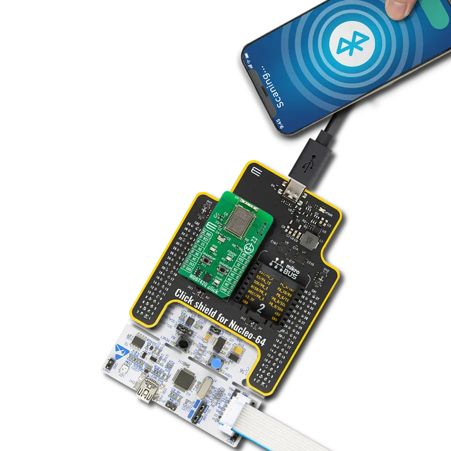
Click Shield for Nucleo-64 comes equipped with two proprietary mikroBUS™ sockets, allowing all the Click board™ devices to be interfaced with the STM32 Nucleo-64 board with no effort. This way, Mikroe allows its users to add any functionality from our ever-growing range of Click boards™, such as WiFi, GSM, GPS, Bluetooth, ZigBee, environmental sensors, LEDs, speech recognition, motor control, movement sensors, and many more. More than 1537 Click boards™, which can be stacked and integrated, are at your disposal. The STM32 Nucleo-64 boards are based on the microcontrollers in 64-pin packages, a 32-bit MCU with an ARM Cortex M4 processor operating at 84MHz, 512Kb Flash, and 96KB SRAM, divided into two regions where the top section represents the ST-Link/V2 debugger and programmer while the bottom section of the board is an actual development board. These boards are controlled and powered conveniently through a USB connection to program and efficiently debug the Nucleo-64 board out of the box, with an additional USB cable connected to the USB mini port on the board. Most of the STM32 microcontroller pins are brought to the IO pins on the left and right edge of the board, which are then connected to two existing mikroBUS™ sockets. This Click Shield also has several switches that perform functions such as selecting the logic levels of analog signals on mikroBUS™ sockets and selecting logic voltage levels of the mikroBUS™ sockets themselves. Besides, the user is offered the possibility of using any Click board™ with the help of existing bidirectional level-shifting voltage translators, regardless of whether the Click board™ operates at a 3.3V or 5V logic voltage level. Once you connect the STM32 Nucleo-64 board with our Click Shield for Nucleo-64, you can access hundreds of Click boards™, working with 3.3V or 5V logic voltage levels.

Used MCU Pins
mikroBUS™ mapper
Take a closer look
Click board™ Schematic

Step by step
Project assembly
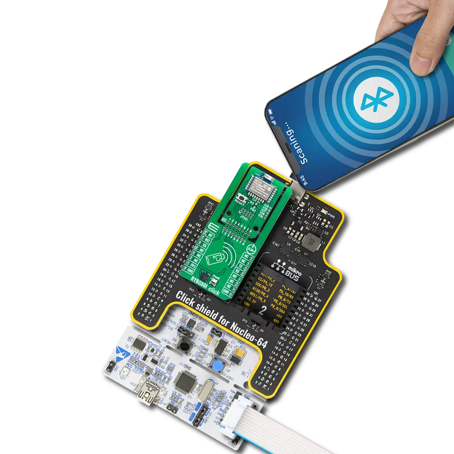
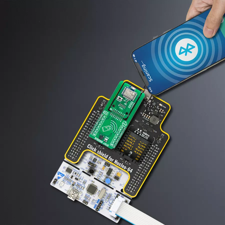
Start by selecting your development board and Click board™. Begin with the Nucleo 64 with STM32F103RB MCU as your development board.


Track your results in real time
Application Output
1. Application Output - In Debug mode, the 'Application Output' window enables real-time data monitoring, offering direct insight into execution results. Ensure proper data display by configuring the environment correctly using the provided tutorial.

2. UART Terminal - Use the UART Terminal to monitor data transmission via a USB to UART converter, allowing direct communication between the Click board™ and your development system. Configure the baud rate and other serial settings according to your project's requirements to ensure proper functionality. For step-by-step setup instructions, refer to the provided tutorial.

3. Plot Output - The Plot feature offers a powerful way to visualize real-time sensor data, enabling trend analysis, debugging, and comparison of multiple data points. To set it up correctly, follow the provided tutorial, which includes a step-by-step example of using the Plot feature to display Click board™ readings. To use the Plot feature in your code, use the function: plot(*insert_graph_name*, variable_name);. This is a general format, and it is up to the user to replace 'insert_graph_name' with the actual graph name and 'variable_name' with the parameter to be displayed.

Software Support
Library Description
This library contains API for RYB080I Click driver.
Key functions:
ryb080i_cmd_run- This function sends a specified command to the click module.ryb080i_cmd_set- This function sets a value to a specified command of the click module.ryb080i_cmd_get- This function is used to get the value of a given command from the click module.
Open Source
Code example
The complete application code and a ready-to-use project are available through the NECTO Studio Package Manager for direct installation in the NECTO Studio. The application code can also be found on the MIKROE GitHub account.
/*!
 * @file main.c
 * @brief RYB080I Click Example.
 *
 * # Description
 * This example demonstrates the use of RYB080I Click board by processing data
 * from a connected BT device.
 *
 * The demo application is composed of two sections :
 *
 * ## Application Init
 * Initializes the driver and logger.
 *
 * ## Application Task
 * Application task is split in few stages:
 *  - RYB080I_POWER_UP:
 * Powers up the device and reads the system information.
 *  - RYB080I_CONFIG_EXAMPLE:
 * Sets the BT device name and enables the full power mode.
 *  - RYB080I_EXAMPLE:
 * Performs a BT terminal example by processing all data from connected BT devices
 * and sending back an adequate response messages.
 *
 * ## Additional Function
 * - static void ryb080i_clear_app_buf ( void )
 * - static void ryb080i_log_app_buf ( void )
 * - static err_t ryb080i_process ( ryb080i_t *ctx )
 * - static err_t ryb080i_read_response ( ryb080i_t *ctx, uint8_t *rsp )
 * - static err_t ryb080i_power_up ( ryb080i_t *ctx )
 * - static err_t ryb080i_config_example ( ryb080i_t *ctx )
 * - static err_t ryb080i_example ( ryb080i_t *ctx )
 *
 * @note
 * We have used the Serial Bluetooth Terminal smartphone application for the test.
 * A smartphone and the Click board must be paired to exchange messages.
 *
 * @author Stefan Filipovic
 *
 */

#include "board.h"
#include "log.h"
#include "ryb080i.h"

// Message content
#define MESSAGE_CONTENT     "RYB080I Click board - demo example."

// Local device name.
#define DEVICE_NAME         "RYB080I Click"

static ryb080i_t ryb080i;
static log_t logger;

// Application buffer size
#define APP_BUFFER_SIZE     600
#define PROCESS_BUFFER_SIZE 200

static uint8_t app_buf[ APP_BUFFER_SIZE ] = { 0 };
static int32_t app_buf_len = 0;

/**
 * @brief Example states.
 * @details Predefined enum values for application example state.
 */
typedef enum
{
    RYB080I_POWER_UP = 1,
    RYB080I_CONFIG_EXAMPLE,
    RYB080I_EXAMPLE

} ryb080i_app_state_t;

static ryb080i_app_state_t app_state = RYB080I_POWER_UP;

/**
 * @brief RYB080I clearing application buffer.
 * @details This function clears memory of application buffer and reset its length.
 * @note None.
 */
static void ryb080i_clear_app_buf ( void );

/**
 * @brief RYB080I log application buffer.
 * @details This function logs data from application buffer to USB UART.
 * @note None.
 */
static void ryb080i_log_app_buf ( void );

/**
 * @brief RYB080I data reading function.
 * @details This function reads data from device and concatenates data to application buffer.
 * @param[in] ctx : Click context object.
 * See #ryb080i_t object definition for detailed explanation.
 * @return @li @c  0 - Read some data.
 *         @li @c -1 - Nothing is read.
 * See #err_t definition for detailed explanation.
 * @note None.
 */
static err_t ryb080i_process ( ryb080i_t *ctx );

/**
 * @brief RYB080I read response function.
 * @details This function waits for a response message, reads and displays it on the USB UART.
 * @param[in] ctx : Click context object.
 * See #ryb080i_t object definition for detailed explanation.
 * @param[in] rsp  Expected response.
 * @return @li @c  0 - OK response.
 *         @li @c -2 - Timeout error.
 *         @li @c -3 - Command error.
 * See #err_t definition for detailed explanation.
 * @note None.
 */
static err_t ryb080i_read_response ( ryb080i_t *ctx, uint8_t *rsp );

/**
 * @brief RYB080I power up function.
 * @details This function powers up the device, and reads the system information.
 * @param[in] ctx : Click context object.
 * See #ryb080i_t object definition for detailed explanation.
 * @return @li @c    0 - OK.
 *         @li @c != 0 - Read response error.
 * See #err_t definition for detailed explanation.
 * @note None.
 */
static err_t ryb080i_power_up ( ryb080i_t *ctx );

/**
 * @brief RYB080I config example function.
 * @details This function sets the BT device name and enables the full power mode.
 * @param[in] ctx : Click context object.
 * See #ryb080i_t object definition for detailed explanation.
 * @return @li @c    0 - OK.
 *         @li @c != 0 - Read response error.
 * See #err_t definition for detailed explanation.
 * @note None.
 */
static err_t ryb080i_config_example ( ryb080i_t *ctx );

/**
 * @brief RYB080I example function.
 * @details This function performs a BT terminal example by processing all data from
 * a connected BT device and sending back an adequate response messages.
 * @param[in] ctx : Click context object.
 * See #ryb080i_t object definition for detailed explanation.
 * @return @li @c    0 - OK.
 *         @li @c != 0 - Read response error.
 * See #err_t definition for detailed explanation.
 * @note None.
 */
static err_t ryb080i_example ( ryb080i_t *ctx );

void application_init ( void )
{
    log_cfg_t log_cfg;  /**< Logger config object. */
    ryb080i_cfg_t ryb080i_cfg;  /**< Click config object. */

    /**
     * Logger initialization.
     * Default baud rate: 115200
     * Default log level: LOG_LEVEL_DEBUG
     * @note If USB_UART_RX and USB_UART_TX
     * are defined as HAL_PIN_NC, you will
     * need to define them manually for log to work.
     * See @b LOG_MAP_USB_UART macro definition for detailed explanation.
     */
    LOG_MAP_USB_UART( log_cfg );
    log_init( &logger, &log_cfg );
    log_info( &logger, " Application Init " );

    // Click initialization.
    ryb080i_cfg_setup( &ryb080i_cfg );
    RYB080I_MAP_MIKROBUS( ryb080i_cfg, MIKROBUS_1 );
    if ( UART_ERROR == ryb080i_init( &ryb080i, &ryb080i_cfg ) )
    {
        log_error( &logger, " Communication init." );
        for ( ; ; );
    }

    log_info( &logger, " Application Task " );

    app_state = RYB080I_POWER_UP;
    log_printf( &logger, ">>> APP STATE - POWER UP <<<\r\n\n" );
}

void application_task ( void )
{
    switch ( app_state )
    {
        case RYB080I_POWER_UP:
        {
            if ( RYB080I_OK == ryb080i_power_up( &ryb080i ) )
            {
                app_state = RYB080I_CONFIG_EXAMPLE;
                log_printf( &logger, ">>> APP STATE - CONFIG EXAMPLE <<<\r\n\n" );
            }
            break;
        }
        case RYB080I_CONFIG_EXAMPLE:
        {
            if ( RYB080I_OK == ryb080i_config_example( &ryb080i ) )
            {
                app_state = RYB080I_EXAMPLE;
                log_printf( &logger, ">>> APP STATE - EXAMPLE <<<\r\n\n" );
            }
            break;
        }
        case RYB080I_EXAMPLE:
        {
            ryb080i_example( &ryb080i );
            break;
        }
        default:
        {
            log_error( &logger, " APP STATE." );
            break;
        }
    }
}

int main ( void )
{
    /* Do not remove this line or clock might not be set correctly. */
    #ifdef PREINIT_SUPPORTED
    preinit();
    #endif

    application_init( );

    for ( ; ; )
    {
        application_task( );
    }

    return 0;
}

static void ryb080i_clear_app_buf ( void )
{
    memset( app_buf, 0, app_buf_len );
    app_buf_len = 0;
}

static void ryb080i_log_app_buf ( void )
{
    for ( int32_t buf_cnt = 0; buf_cnt < app_buf_len; buf_cnt++ )
    {
        log_printf( &logger, "%c", app_buf[ buf_cnt ] );
    }
}

static err_t ryb080i_process ( ryb080i_t *ctx )
{
    uint8_t rx_buf[ PROCESS_BUFFER_SIZE ] = { 0 };
    int32_t overflow_bytes = 0;
    int32_t rx_cnt = 0;
    int32_t rx_size = ryb080i_generic_read( ctx, rx_buf, PROCESS_BUFFER_SIZE );
    if ( ( rx_size > 0 ) && ( rx_size <= APP_BUFFER_SIZE ) )
    {
        if ( ( app_buf_len + rx_size ) > APP_BUFFER_SIZE )
        {
            overflow_bytes = ( app_buf_len + rx_size ) - APP_BUFFER_SIZE;
            app_buf_len = APP_BUFFER_SIZE - rx_size;
            memmove ( app_buf, &app_buf[ overflow_bytes ], app_buf_len );
            memset ( &app_buf[ app_buf_len ], 0, overflow_bytes );
        }
        for ( rx_cnt = 0; rx_cnt < rx_size; rx_cnt++ )
        {
            if ( rx_buf[ rx_cnt ] )
            {
                app_buf[ app_buf_len++ ] = rx_buf[ rx_cnt ];
            }
        }
        return RYB080I_OK;
    }
    return RYB080I_ERROR;
}

static err_t ryb080i_read_response ( ryb080i_t *ctx, uint8_t *rsp )
{
    #define READ_RESPONSE_TIMEOUT_MS 30000
    uint32_t timeout_cnt = 0;
    ryb080i_clear_app_buf ( );
    ryb080i_process( ctx );
    while ( 0 == strstr( app_buf, rsp ) )
    {
        ryb080i_process( ctx );
        if ( timeout_cnt++ > READ_RESPONSE_TIMEOUT_MS )
        {
            ryb080i_clear_app_buf( );
            log_error( &logger, " Timeout!" );
            return RYB080I_ERROR_TIMEOUT;
        }
        Delay_ms ( 1 );
    }
    Delay_ms ( 200 );
    ryb080i_process( ctx );
    if ( strstr( app_buf, rsp ) )
    {
        ryb080i_log_app_buf( );
        log_printf( &logger, "--------------------------------\r\n" );
        return RYB080I_OK;
    }
    ryb080i_log_app_buf( );
    return RYB080I_ERROR_CMD;
}

static err_t ryb080i_power_up ( ryb080i_t *ctx )
{
    err_t error_flag = RYB080I_OK;

    log_printf( &logger, ">>> Reset device.\r\n" );
    ryb080i_reset_device( &ryb080i );
    error_flag |= ryb080i_read_response( ctx, RYB080I_RSP_READY );

    log_printf( &logger, ">>> Check communication.\r\n" );
    ryb080i_cmd_run( &ryb080i, RYB080I_CMD_AT );
    error_flag |= ryb080i_read_response( &ryb080i, RYB080I_RSP_OK );

    log_printf( &logger, ">>> Get software version.\r\n" );
    ryb080i_cmd_get( ctx, RYB080I_CMD_SW_VERSION );
    error_flag |= ryb080i_read_response( ctx, RYB080I_RSP_GENERIC );

    log_printf( &logger, ">>> Get MAC address.\r\n" );
    ryb080i_cmd_get( ctx, RYB080I_CMD_INQUIRE_MAC_ADDRESS );
    error_flag |= ryb080i_read_response( ctx, RYB080I_RSP_GENERIC );

    return error_flag;
}

static err_t ryb080i_config_example ( ryb080i_t *ctx )
{
    err_t error_flag = RYB080I_OK;

    log_printf( &logger, ">>> Set broadcast name to \"%s\".\r\n", ( char * ) DEVICE_NAME );
    ryb080i_cmd_set( ctx, RYB080I_CMD_BROADCAST_NAME, DEVICE_NAME );
    error_flag |= ryb080i_read_response( ctx, RYB080I_RSP_OK );

    log_printf( &logger, ">>> Set device name to \"%s\".\r\n", ( char * ) DEVICE_NAME );
    ryb080i_cmd_set( ctx, RYB080I_CMD_BROADCAST_NAME, DEVICE_NAME );
    error_flag |= ryb080i_read_response( ctx, RYB080I_RSP_OK );

    log_printf( &logger, ">>> Software reset.\r\n" );
    ryb080i_cmd_run( ctx, RYB080I_CMD_SW_RESET );
    error_flag |= ryb080i_read_response( ctx, RYB080I_RSP_READY );

    #define FULL_POWER_MODE "0"
    log_printf( &logger, ">>> Set full power mode.\r\n" );
    ryb080i_cmd_set( ctx, RYB080I_CMD_POWER_MODE, FULL_POWER_MODE );
    error_flag |= ryb080i_read_response( ctx, RYB080I_RSP_OK );

    return error_flag;
}

static err_t ryb080i_example ( ryb080i_t *ctx )
{
    err_t error_flag = RYB080I_OK;
    uint8_t * __generic_ptr urc_buf_ptr = 0;
    uint8_t bt_peer_handle[ 2 ] = { 0 };
    uint32_t timeout_cnt = 0;

    #define BT_TERMINAL_TIMEOUT_MS      60000
    #define BT_TERMINAL_MESSAGE_FREQ_MS 5000
    #define TERMINATION_CMD             "END"
    #define TERMINATION_RESPONSE        "END command received, the connection will be terminated in a few seconds."
    #define TERMINATION_TIMEOUT         "Timeout, closing the connection in a few seconds."
    #define NEW_LINE_STRING             "\r\n"
    #define DISCONNECT_ALL_PEERS        "0"

    log_printf( &logger, ">>> Waiting for a BT peer to establish connection with the Click board...\r\n" );
    for ( ; ; )
    {
        ryb080i_clear_app_buf( );
        if ( RYB080I_OK == ryb080i_process( ctx ) )
        {
            Delay_ms ( 200 );
            ryb080i_process( ctx );
            ryb080i_log_app_buf( );
            if ( strstr( app_buf, RYB080I_RSP_CONNECTED ) )
            {
                urc_buf_ptr = strstr( app_buf, RYB080I_RSP_CONNECTED ) + strlen ( RYB080I_RSP_CONNECTED ) + 1;
                bt_peer_handle[ 0 ] = *urc_buf_ptr;
                log_printf( &logger, ">>> BT peer %s has connected.\r\n", bt_peer_handle );
                break;
            }
        }
    }

    log_printf( &logger, ">>> Waiting for data (up to 60 seconds)...\r\n" );
    log_printf( &logger, ">>> Connection will be terminated if the Click receives an \"END\" string.\r\n" );
    for ( ; ; )
    {
        ryb080i_clear_app_buf( );
        if ( RYB080I_OK == ryb080i_process( ctx ) )
        {
            Delay_ms ( 200 );
            timeout_cnt = 0;
            ryb080i_process( ctx );
            ryb080i_log_app_buf( );
            if ( strstr( app_buf, TERMINATION_CMD ) )
            {
                log_printf( &logger, ">>> Terminating connection on demand.\r\n" );
                ryb080i_cmd_run ( ctx, TERMINATION_RESPONSE );
                error_flag |= ryb080i_read_response( ctx, RYB080I_RSP_OK );

                log_printf( &logger, ">>> Disconnecting all BT peers.\r\n" );
                ryb080i_cmd_set ( ctx, RYB080I_CMD_DISCONNECT, DISCONNECT_ALL_PEERS );
                error_flag |= ryb080i_read_response( ctx, RYB080I_RSP_DISCONNECTED );
                break;
            }
            else if ( strstr( app_buf, RYB080I_RSP_DISCONNECTED ) )
            {
                urc_buf_ptr = strstr( app_buf, RYB080I_RSP_DISCONNECTED ) + strlen ( RYB080I_RSP_DISCONNECTED ) + 1;
                bt_peer_handle[ 0 ] = *urc_buf_ptr;
                log_printf( &logger, ">>> BT peer %s has disconnected.\r\n", bt_peer_handle );

                log_printf( &logger, ">>> Checking if there are more peers connected.\r\n" );
                ryb080i_cmd_get ( ctx, RYB080I_CMD_CONNECTION_STATUS );
            }
            else if ( strstr( app_buf, RYB080I_RSP_CONNECTED ) )
            {
                urc_buf_ptr = strstr( app_buf, RYB080I_RSP_CONNECTED ) + strlen ( RYB080I_RSP_CONNECTED ) + 1;
                bt_peer_handle[ 0 ] = *urc_buf_ptr;
                log_printf( &logger, ">>> BT peer %s has connected.\r\n", bt_peer_handle );
            }
            else if ( strstr( app_buf, RYB080I_RSP_NO_CONNECTIONS ) )
            {
                break;
            }
        }
        timeout_cnt++;
        if ( 0 == ( timeout_cnt % BT_TERMINAL_MESSAGE_FREQ_MS ) )
        {
            log_printf( &logger, ">>> Sending \"%s\" message to connected device.\r\n", ( char * ) MESSAGE_CONTENT );
            ryb080i_cmd_run ( ctx, MESSAGE_CONTENT );
            error_flag |= ryb080i_read_response( ctx, RYB080I_RSP_OK );
        }
        if ( BT_TERMINAL_TIMEOUT_MS < timeout_cnt )
        {
            log_printf( &logger, ">>> Terminating connection due to 60s timeout expiration.\r\n" );
            ryb080i_cmd_run ( ctx, TERMINATION_TIMEOUT );
            error_flag |= ryb080i_read_response( ctx, RYB080I_RSP_OK );

            log_printf( &logger, ">>> Disconnecting all BT peers.\r\n" );
            ryb080i_cmd_set ( ctx, RYB080I_CMD_DISCONNECT, DISCONNECT_ALL_PEERS );
            error_flag |= ryb080i_read_response( ctx, RYB080I_RSP_DISCONNECTED );
            break;
        }
        Delay_ms ( 1 );
    }

    return error_flag;
}

// ------------------------------------------------------------------------ END
Additional Support
Resources
Category:BT/BLE