Improve your projects with BLE 4.2 using RN4871 and PIC32MZ2048EFH100
Easy connectivity at your fingertips!
Published Jul 27, 2023
Click board™
RN4871 click
Dev. board
Flip&Click PIC32MZ
Compiler
NECTO Studio
MCU
PIC32MZ2048EFH100
Unlock the full potential of your projects with our BLE 4.2 module, crafted to enable effortless wireless communication while conserving energy. Enhance your experience, and enable seamless connectivity and efficient data transfer in applications ranging from industrial automation to smart home devices.
A
A
Hardware Overview
How does it work?
RN4871 Click is based on the RN4871, a Bluetooth® 4.2 low-energy module from Microchip. This Click is designed to run on a 3.3V power supply. It uses ASCII Command Interface over UART for communication with the target microcontroller, with additional functionality provided by the following pins on the mikroBUS™ line: RST, CS, and INT. The RN4871 Bluetooth Low
Energy module integrates Bluetooth 4.2 baseband controller, onboard Bluetooth stack, digital and analog I/O, and RF power amplifier into one solution. The module contains an integral ceramic chip antenna. The host microcontroller can dynamically configure all products in the RN series with a few simple ASCII commands. The RN4871 supports both peripheral and central Generic
Access Profile (GAP) roles, actively scanning for other connectable devices instead of waiting for incoming connection requests. The peripherals are usually small, low-power devices that broadcast information to the central device, like sensors and monitors. The central device can communicate with multiple peripherals.

Features overview
Development board
Flip&Click PIC32MZ is a compact development board designed as a complete solution that brings the flexibility of add-on Click boards™ to your favorite microcontroller, making it a perfect starter kit for implementing your ideas. It comes with an onboard 32-bit PIC32MZ microcontroller, the PIC32MZ2048EFH100 from Microchip, four mikroBUS™ sockets for Click board™ connectivity, two USB connectors, LED indicators, buttons, debugger/programmer connectors, and two headers compatible with Arduino-UNO pinout. Thanks to innovative manufacturing technology,
it allows you to build gadgets with unique functionalities and features quickly. Each part of the Flip&Click PIC32MZ development kit contains the components necessary for the most efficient operation of the same board. In addition, there is the possibility of choosing the Flip&Click PIC32MZ programming method, using the chipKIT bootloader (Arduino-style development environment) or our USB HID bootloader using mikroC, mikroBasic, and mikroPascal for PIC32. This kit includes a clean and regulated power supply block through the USB Type-C (USB-C) connector. All communication
methods that mikroBUS™ itself supports are on this board, including the well-established mikroBUS™ socket, user-configurable buttons, and LED indicators. Flip&Click PIC32MZ development kit allows you to create a new application in minutes. Natively supported by Mikroe software tools, it covers many aspects of prototyping thanks to a considerable number of different Click boards™ (over a thousand boards), the number of which is growing every day.

Microcontroller Overview
MCU Card / MCU

Architecture
PIC32
MCU Memory (KB)
2048
Silicon Vendor
Microchip
Pin count
100
RAM (Bytes)
524288
Used MCU Pins
mikroBUS™ mapper
Take a closer look
Click board™ Schematic

Step by step
Project assembly

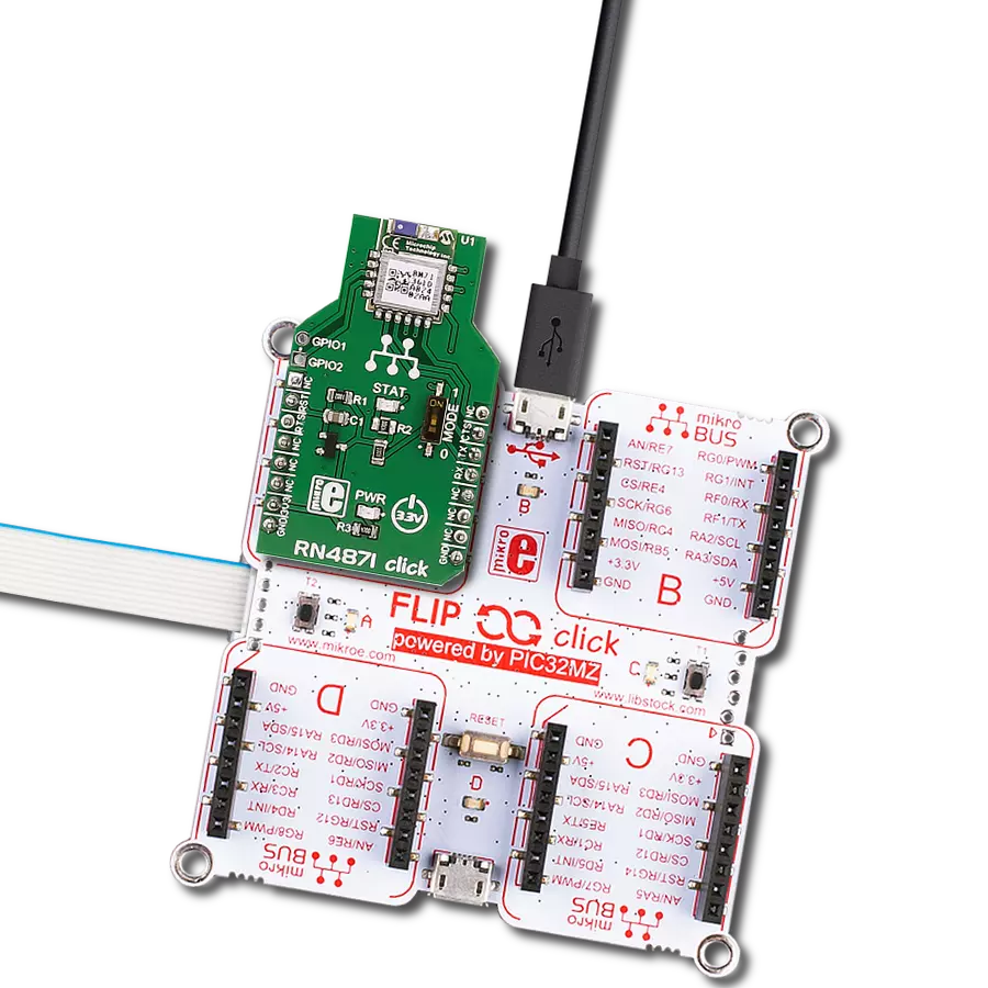
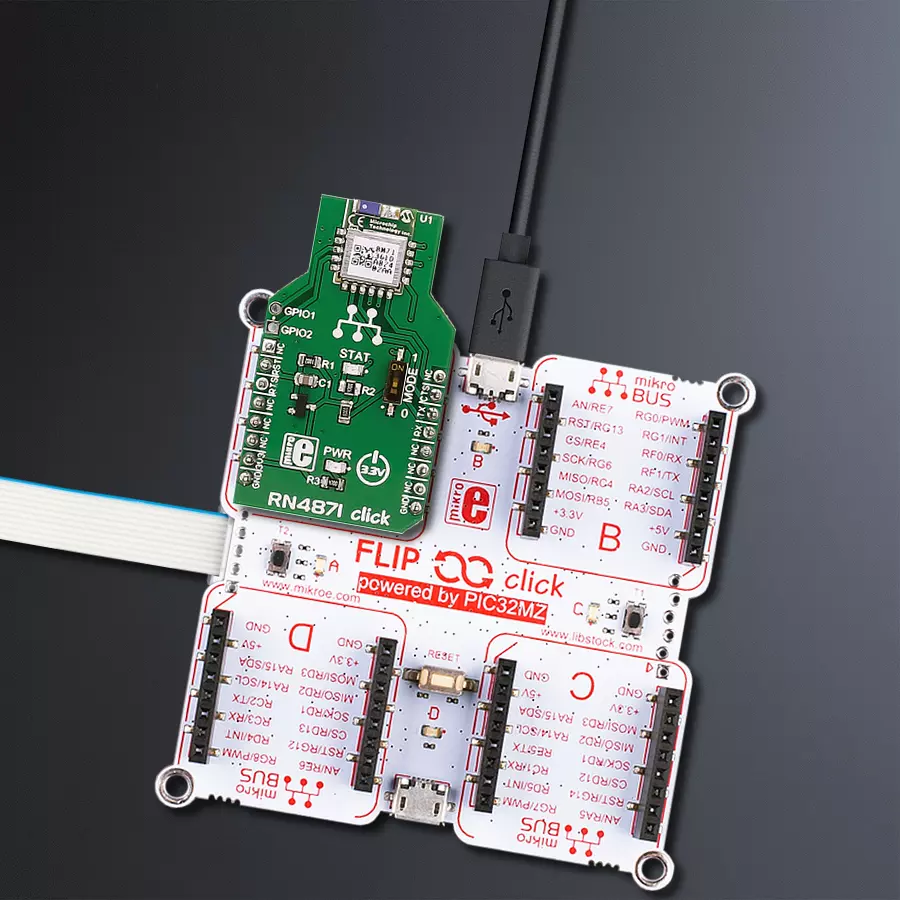
Start by selecting your development board and Click board™. Begin with the Flip&Click PIC32MZ as your development board.


Software Support
Library Description
This library contains API for RN4870 Click driver.
Key functions:
rn4871_read- This function gets message from 'void rn4871_receive function if flag was setrn4871_receive- The function receives character by waits for '#' - character to start parsing message, waits for '*' - character to stop parsing message and sets flag if whole and properly formated message is receivedrn4871_connect- The function connects to slave device with desired register address by secures the connection and entering data stream mode
Open Source
Code example
The complete application code and a ready-to-use project are available through the NECTO Studio Package Manager for direct installation in the NECTO Studio. The application code can also be found on the MIKROE GitHub account.
/*!
 * \file
 * \brief Rn4871 Click example
 *
 * # Description
 * This example reads and processes data from RN4871 Clicks.
 *
 * The demo application is composed of two sections :
 *
 * ## Application Init
 * Initializes UART driver. Initializes device and parser.
 *
 * ## Application Task
 * If 'MASTER' - connects to 'SLAVE', sends message and disconnects. If 'SLAVE' - waits for connect request
 * and message from 'MASTER' and LOGs received message.
 *
 * ## Additional Function
 * - rn4871_process ( ) - The general process of collecting presponce
 *                                   that sends a module.
 *
 *
 * \author MikroE Team
 *
 */
// ------------------------------------------------------------------- INCLUDES

#include "board.h"
#include "log.h"
#include "rn4871.h"
#include "string.h"

#define PROCESS_COUNTER 10
#define PROCESS_RX_BUFFER_SIZE 500
#define PROCESS_PARSER_BUFFER_SIZE 500

// ------------------------------------------------------------------ VARIABLES

// #define DEMO_APP_RECEIVER
#define DEMO_APP_TRANSMITER

static rn4871_t rn4871;
static log_t logger;

uint8_t RN4871_ADDR_MASTER[ 13 ] = {'D', 'F', '0', '0', '0', '0', '0', '6', '8', '7', '9', '0'};
uint8_t RN4871_ADDR_SLAVE[ 13 ] = {'D', 'F', '1', '1', '1', '1', '1', '6', '8', '7', '9', '0'};
uint8_t message_payload[ 17 ] = {'M', 'i', 'k', 'r', 'o', 'E', 'l', 'e', 'k', 't', 'r', 'o', 'n', 'i', 'k', 'a'};

uint8_t dev_type;
uint8_t receive_buffer[ 255 ];
uint8_t msg_flag = 0;
char *ptr;

// ------------------------------------------------------- ADDITIONAL FUNCTIONS

static void rn4871_process ( void )
{
    int32_t rsp_size;

    char uart_rx_buffer[ PROCESS_RX_BUFFER_SIZE ] = { 0 };
    uint8_t check_buf_cnt;


    rsp_size = rn4871_generic_read( &rn4871, &uart_rx_buffer, PROCESS_RX_BUFFER_SIZE );

    if ( rsp_size > 0 )
    {
        // Validation of the received data
        for ( check_buf_cnt = 0; check_buf_cnt < rsp_size; check_buf_cnt++ )
        {
            rn4871_receive( &rn4871, uart_rx_buffer[ check_buf_cnt ] );
        }
    }
}

// ------------------------------------------------------ APPLICATION FUNCTIONS

void application_init ( void )
{
    log_cfg_t log_cfg;
    rn4871_cfg_t cfg;

    /**
     * Logger initialization.
     * Default baud rate: 115200
     * Default log level: LOG_LEVEL_DEBUG
     * @note If USB_UART_RX and USB_UART_TX
     * are defined as HAL_PIN_NC, you will
     * need to define them manually for log to work.
     * See @b LOG_MAP_USB_UART macro definition for detailed explanation.
     */
    LOG_MAP_USB_UART( log_cfg );
    log_init( &logger, &log_cfg );
    log_info( &logger, "---- Application Init ----" );

    //  Click initialization.

    rn4871_cfg_setup( &cfg );
    RN4871_MAP_MIKROBUS( cfg, MIKROBUS_1 );
    rn4871_init( &rn4871, &cfg );
    Delay_ms ( 100 );

    dev_type = RN4871_DEVICETYPE_MASTER;

#ifdef DEMO_APP_TRANSMITER
    log_info( &logger, "RN4871 DEVICE TYPE MASTER" );
    rn4871_initialize( &rn4871, &RN4871_ADDR_MASTER[ 0 ] );
#endif
#ifdef DEMO_APP_RECEIVER
    log_info( &logger, "RN4871 DEVICE TYPE SLAVE" );
    rn4871_initialize( &rn4871, &RN4871_ADDR_SLAVE[ 0 ] );
    ptr = &receive_buffer[ 7 ];
#endif

    memset( &rn4871.device_buffer, 0, 255 );
    log_printf( &logger, " >>> app init done <<<  \r\n" );
}

void application_task ( void )
{
    rn4871_process(  );
#ifdef DEMO_APP_TRANSMITER
    rn4871_connect( &rn4871, &RN4871_ADDR_SLAVE[ 0 ] );
    Delay_ms ( 100 );
    log_printf( &logger, ">>> sending data  <<<\r\n" );
    rn4871_send( &rn4871, RN4871_MTYPE_MSG, RN4871_DTYPE_STRING, RN4871_ID_MASTER, &message_payload[ 0 ] );
    Delay_ms ( 100 );
    rn4871_disconnect( &rn4871 );
    Delay_ms ( 100 );
#endif

#ifdef DEMO_APP_RECEIVER
    msg_flag = rn4871_read( &rn4871, &receive_buffer[ 0 ] );

    if ( msg_flag == 1 )
    {
        log_printf( &logger, ">>> data received <<<\r\n" );
        log_printf( &logger, ">>> data : " );
        log_printf( &logger, "%s\r\n", ptr );
    }
#endif
}

int main ( void )
{
    /* Do not remove this line or clock might not be set correctly. */
    #ifdef PREINIT_SUPPORTED
    preinit();
    #endif

    application_init( );

    for ( ; ; )
    {
        application_task( );
    }

    return 0;
}


// ------------------------------------------------------------------------ END
Additional Support
Resources
Category:BT/BLE


