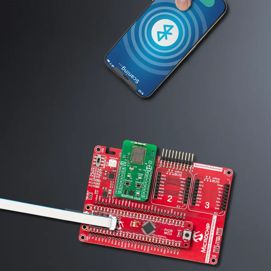
Add Bluetooth Low Energy connectivity to embedded designs with MDBT42Q-AT2 and PIC18F57Q43
Easy-to-use, low-power Bluetooth LE connectivity solution for IoT and smart applications

Published Sep 29, 2025
Click board™
MDBT42Q Click
Dev. board
Curiosity Nano with PIC18F57Q43
Compiler
NECTO Studio
MCU
PIC18F57Q43
Your go-to solution for any project requiring easy-to-use and dependable Bluetooth LE functionality
A
A
Hardware Overview
How does it work?
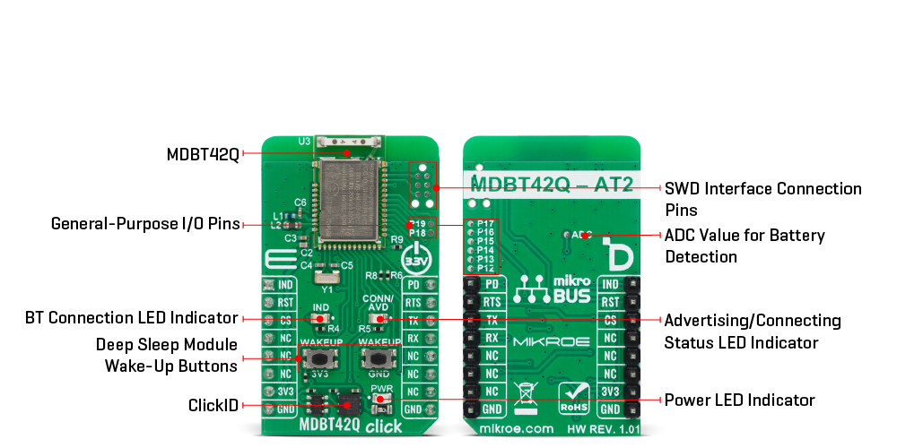
MDBT42Q Click is based on the MDBT42Q-AT2 module from RAYTAC designed to provide Bluetooth Low Energy (BLE) connectivity. This certified BT 5.2 stack module is based on the Nordic nRF52810 SoC, a highly integrated solution that combines a 32-bit ARM Cortex-M4F processor with 192kB of Flash memory and 24kB of RAM, ensuring efficient operation in wireless applications. Acting exclusively in the peripheral/slave role, the module comes preloaded with RAYTAC’s AT command firmware, which simplifies configuration and control through a UART interface. As a recommended third-party module by Nordic Semiconductor, MDBT42Q-AT2 meets multiple international standards, being certified for FCC, IC, CE, Telec (MIC), KC, SRRC, and NCC compliance, while its onboard chip antenna guarantees excellent connectivity performance in compact embedded designs. The module offers flexible configuration options, allowing users to choose on-air data rates of either 1Mbps or 2Mbps, set transmission power across five selectable levels, and adjust advertising time. For better user interaction, it supports customizable LED indication patterns that reflect advertising and connection status, with a yellow CONN/ADV LED as a clear status marker. To optimize energy consumption, it provides both DC-to-DC and LDO power modes, a dedicated power-down state with GPIO wake-up
support, and efficient use of resources to extend battery life in portable systems. Its data handling capabilities include support for a maximum MTU size of 247 bytes, enabling payloads of up to 244 bytes, ensuring reliable and flexible data exchange in BLE applications. With these features, MDBT42Q Click is ideal for IoT devices, wireless sensors, smart home automation, asset tracking systems, healthcare and fitness monitors, and other scenarios where low-power, short-range wireless connectivity is required. This Click board™ establishes communication between the MDBT42Q-AT2 module and the host MCU through a UART interface, using standard UART RX and TX pins and hardware flow control via CTS and RTS pins. The default communication speed is set at 115200bps, ensuring efficient data exchange. In addition to the UART pins for communication with the module, this Click board also features a PD active-high pin used to enable the UART interface, a reset pin (RST) enabling easy module resetting, blue IND LED indicator for Bluetooth connection status (also available through IND pin), and SWD pads designed for use with MIKROE's 6-pin Needle Cable, providing an optional flash and debug SWD (Serial Wire Debug) interface functionality. The board integrates dedicated wake-up buttons that provide a reliable way to bring the module out of deep sleep mode. Since the wake-up mechanism is
logic-selective, it requires a clearly defined signal transition to activate the module, which is why two separate buttons are provided: one tied to the 3V3 rail and the other to GND. By pressing either of these, a valid high or low logic level is momentarily introduced, triggering the wake-up event in accordance with the module’s power management logic. The board is also equipped with a set of carefully placed test points that provide developers with easy access to key signals for debugging, monitoring, and feature expansion. A dedicated group of test points labeled P12 through P19 enables support for up to eight programmable GPIO outputs, offering flexibility to configure these pins according to application requirements. In addition to general-purpose I/O, an ADC test point is also provided, allowing straightforward retrieval of analog-to-digital conversion values. This feature is particularly useful for monitoring supply conditions, most notably battery voltage levels, ensuring that power status can be tracked in real time and incorporated into the system’s operation logic. This Click board™ can be operated only with a 3.3V logic voltage level. The board must perform appropriate logic voltage level conversion before using MCUs with different logic levels. It also comes equipped with a library containing functions and example code that can be used as a reference for further development.
Features overview
Development board
PIC18F57Q43 Curiosity Nano evaluation kit is a cutting-edge hardware platform designed to evaluate microcontrollers within the PIC18-Q43 family. Central to its design is the inclusion of the powerful PIC18F57Q43 microcontroller (MCU), offering advanced functionalities and robust performance. Key features of this evaluation kit include a yellow user LED and a responsive
mechanical user switch, providing seamless interaction and testing. The provision for a 32.768kHz crystal footprint ensures precision timing capabilities. With an onboard debugger boasting a green power and status LED, programming and debugging become intuitive and efficient. Further enhancing its utility is the Virtual serial port (CDC) and a debug GPIO channel (DGI
GPIO), offering extensive connectivity options. Powered via USB, this kit boasts an adjustable target voltage feature facilitated by the MIC5353 LDO regulator, ensuring stable operation with an output voltage ranging from 1.8V to 5.1V, with a maximum output current of 500mA, subject to ambient temperature and voltage constraints.

Microcontroller Overview
MCU Card / MCU

Architecture
PIC
MCU Memory (KB)
128
Silicon Vendor
Microchip
Pin count
48
RAM (Bytes)
8196
You complete me!
Accessories
Curiosity Nano Base for Click boards is a versatile hardware extension platform created to streamline the integration between Curiosity Nano kits and extension boards, tailored explicitly for the mikroBUS™-standardized Click boards and Xplained Pro extension boards. This innovative base board (shield) offers seamless connectivity and expansion possibilities, simplifying experimentation and development. Key features include USB power compatibility from the Curiosity Nano kit, alongside an alternative external power input option for enhanced flexibility. The onboard Li-Ion/LiPo charger and management circuit ensure smooth operation for battery-powered applications, simplifying usage and management. Moreover, the base incorporates a fixed 3.3V PSU dedicated to target and mikroBUS™ power rails, alongside a fixed 5.0V boost converter catering to 5V power rails of mikroBUS™ sockets, providing stable power delivery for various connected devices.

Used MCU Pins
mikroBUS™ mapper
Take a closer look
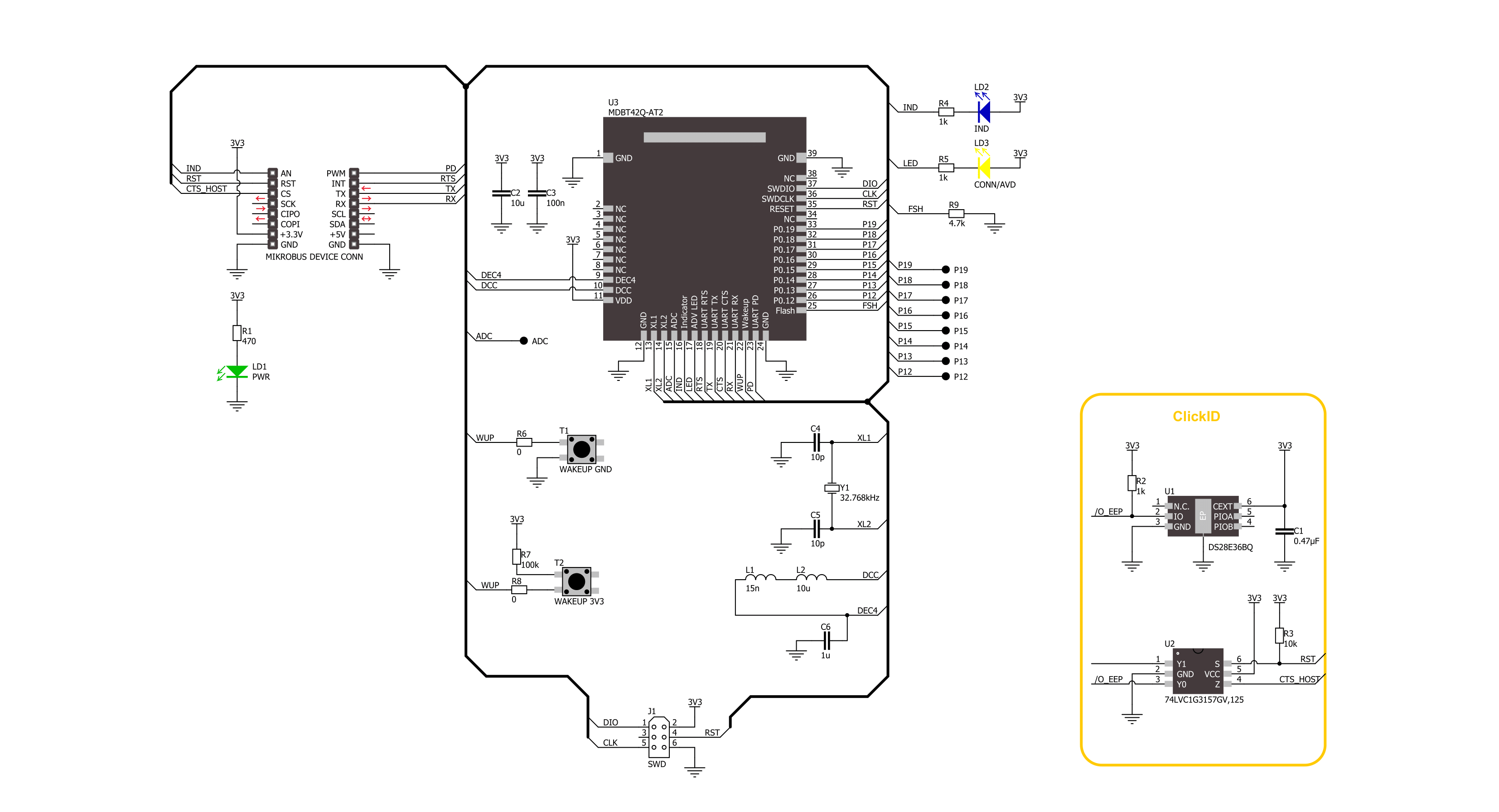
Click board™ Schematic
Step by step
Project assembly

Start by selecting your development board and Click board™. Begin with the Curiosity Nano with PIC18F57Q43 as your development board.


Software Support
Library Description
MDBT42Q Click demo application is developed using the NECTO Studio, ensuring compatibility with mikroSDK's open-source libraries and tools. Designed for plug-and-play implementation and testing, the demo is fully compatible with all development, starter, and mikromedia boards featuring a mikroBUS™ socket.
Example Description
This example demonstrates the use of MDBT42Q Click board by processing data from a connected BT device.
Key functions:
mdbt42q_cfg_setup- This function initializes Click configuration structure to initial values.mdbt42q_init- This function initializes all necessary pins and peripherals used for this Click board.mdbt42q_get_ind_pin- This function returns the BT connection active indicator (IND) pin logic state.mdbt42q_reset_device- This function resets the device by toggling the reset pin logic state.mdbt42q_cmd_run- This function sends a specified command to the Click module.mdbt42q_cmd_set- This function sets a value to a specified command of the Click module.
Application Init
Initializes the driver and logger.
Application Task
Application task is split in few stages:
MDBT42Q_POWER_UP- Powers up the device, performs a factory reset and reads system information.MDBT42Q_CONFIG_EXAMPLE- Sets the BT device name.MDBT42Q_EXAMPLE- Performs a BT terminal example by processing all data from a connected BT device and sending back an adequate response messages.
Open Source
Code example
The complete application code and a ready-to-use project are available through the NECTO Studio Package Manager for direct installation in the NECTO Studio. The application code can also be found on the MIKROE GitHub account.
/*!
* @file main.c
* @brief MDBT42Q Click Example.
*
* # Description
* This example demonstrates the use of MDBT42Q Click board by processing data
* from a connected BT device.
*
* The demo application is composed of two sections :
*
* ## Application Init
* Initializes the driver and logger.
*
* ## Application Task
* Application task is split in few stages:
* - MDBT42Q_POWER_UP:
* Powers up the device, performs a factory reset and reads system information.
* - MDBT42Q_CONFIG_EXAMPLE:
* Sets the BT device name.
* - MDBT42Q_EXAMPLE:
* Performs a BT terminal example by processing all data from a connected BT device
* and sending back an adequate response messages.
*
* ## Additional Function
* - static void mdbt42q_clear_app_buf ( void )
* - static void mdbt42q_log_app_buf ( void )
* - static err_t mdbt42q_process ( mdbt42q_t *ctx )
* - static err_t mdbt42q_read_response ( mdbt42q_t *ctx )
* - static err_t mdbt42q_power_up ( mdbt42q_t *ctx )
* - static err_t mdbt42q_config_example ( mdbt42q_t *ctx )
* - static err_t mdbt42q_example ( mdbt42q_t *ctx )
*
* @note
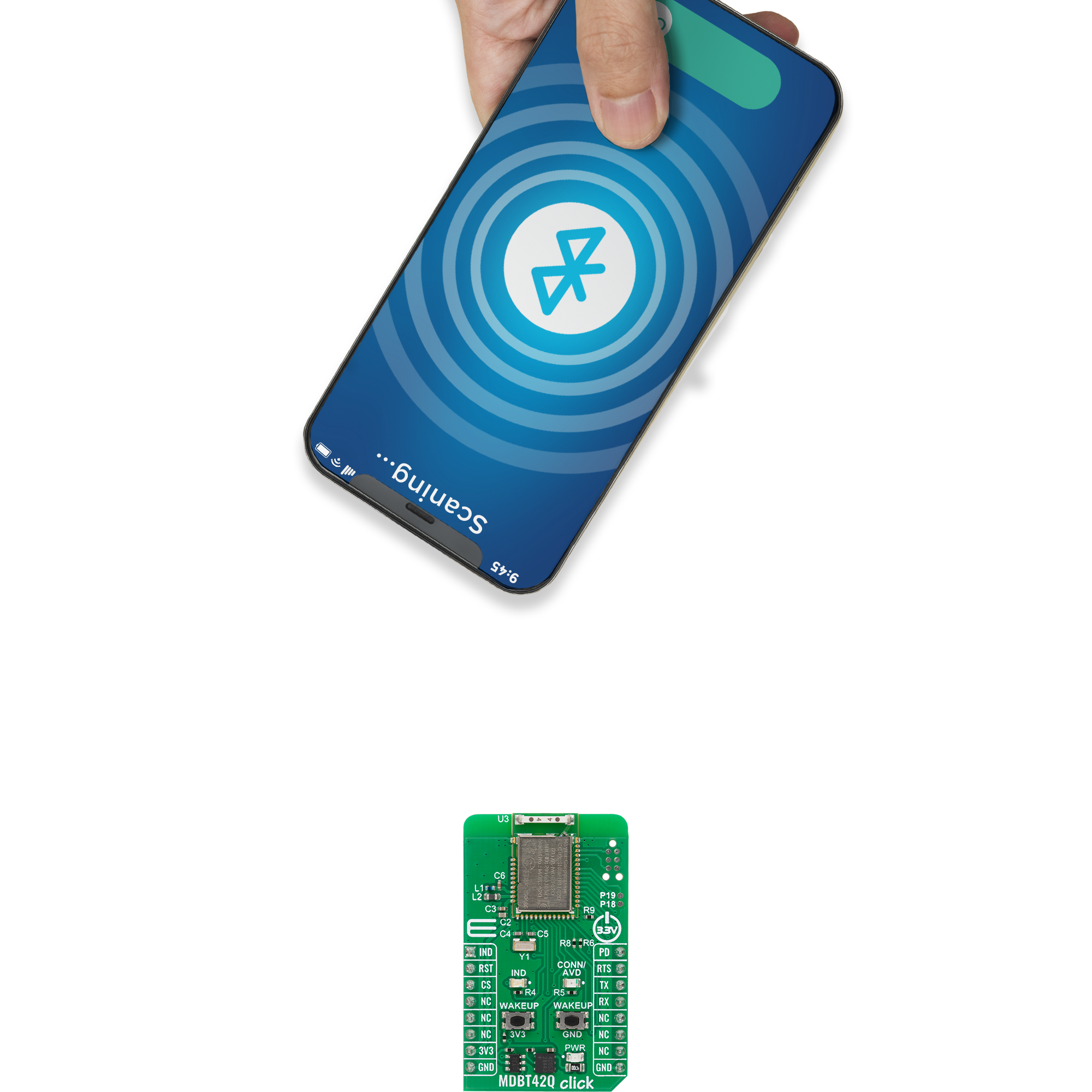
* We have used the Serial Bluetooth Terminal smartphone application for the test.
*
* @author Stefan Filipovic
*
*/
#include "board.h"
#include "log.h"
#include "mdbt42q.h"
// Message content
#define MESSAGE_CONTENT "MDBT42Q Click board - demo example."
// Device name.
#define DEVICE_NAME "MDBT42Q Click"
static mdbt42q_t mdbt42q;
static log_t logger;
// Application buffer size
#define APP_BUFFER_SIZE 600
#define PROCESS_BUFFER_SIZE 200
static uint8_t app_buf[ APP_BUFFER_SIZE ] = { 0 };
static int32_t app_buf_len = 0;
/**
* @brief Example states.
* @details Predefined enum values for application example state.
*/
typedef enum
{
MDBT42Q_POWER_UP = 1,
MDBT42Q_CONFIG_EXAMPLE,
MDBT42Q_EXAMPLE
} mdbt42q_app_state_t;
static mdbt42q_app_state_t app_state = MDBT42Q_POWER_UP;
/**
* @brief MDBT42Q clearing application buffer.
* @details This function clears memory of application buffer and reset its length.
* @note None.
*/
static void mdbt42q_clear_app_buf ( void );
/**
* @brief MDBT42Q log application buffer.
* @details This function logs data from application buffer to USB UART.
* @note None.
*/
static void mdbt42q_log_app_buf ( void );
/**
* @brief MDBT42Q data reading function.
* @details This function reads data from device and concatenates data to application buffer.
* @param[in] ctx : Click context object.
* See #mdbt42q_t object definition for detailed explanation.
* @return @li @c 0 - Read some data.
* @li @c -1 - Nothing is read.
* See #err_t definition for detailed explanation.
* @note None.
*/
static err_t mdbt42q_process ( mdbt42q_t *ctx );
/**
* @brief MDBT42Q read response function.
* @details This function waits for a response message, reads and displays it on the USB UART.
* @param[in] ctx : Click context object.
* See #mdbt42q_t object definition for detailed explanation.
* @return @li @c 0 - OK response.
* @li @c -2 - Timeout error.
* See #err_t definition for detailed explanation.
* @note None.
*/
static err_t mdbt42q_read_response ( mdbt42q_t *ctx );
/**
* @brief MDBT42Q power up function.
* @details This function powers up the device, performs a factory reset and reads system information.
* @param[in] ctx : Click context object.
* See #mdbt42q_t object definition for detailed explanation.
* @return @li @c 0 - OK.
* @li @c != 0 - Read response error.
* See #err_t definition for detailed explanation.
* @note None.
*/
static err_t mdbt42q_power_up ( mdbt42q_t *ctx );
/**
* @brief MDBT42Q config example function.
* @details This function sets the BT device name.
* @param[in] ctx : Click context object.
* See #mdbt42q_t object definition for detailed explanation.
* @return @li @c 0 - OK.
* @li @c != 0 - Read response error.
* See #err_t definition for detailed explanation.
* @note None.
*/
static err_t mdbt42q_config_example ( mdbt42q_t *ctx );
/**
* @brief MDBT42Q example function.
* @details This function performs a BT terminal example by processing all data from
* a connected BT device and sending back an adequate response messages.
* @param[in] ctx : Click context object.
* See #mdbt42q_t object definition for detailed explanation.
* @return @li @c 0 - OK.
* @li @c != 0 - Read response error.
* See #err_t definition for detailed explanation.
* @note None.
*/
static err_t mdbt42q_example ( mdbt42q_t *ctx );
void application_init ( void )
{
log_cfg_t log_cfg; /**< Logger config object. */
mdbt42q_cfg_t mdbt42q_cfg; /**< Click config object. */
/**
* Logger initialization.
* Default baud rate: 115200
* Default log level: LOG_LEVEL_DEBUG
* @note If USB_UART_RX and USB_UART_TX
* are defined as HAL_PIN_NC, you will
* need to define them manually for log to work.
* See @b LOG_MAP_USB_UART macro definition for detailed explanation.
*/
LOG_MAP_USB_UART( log_cfg );
log_init( &logger, &log_cfg );
log_info( &logger, " Application Init " );
// Click initialization.
mdbt42q_cfg_setup( &mdbt42q_cfg );
MDBT42Q_MAP_MIKROBUS( mdbt42q_cfg, MIKROBUS_1 );
if ( MDBT42Q_OK != mdbt42q_init( &mdbt42q, &mdbt42q_cfg ) )
{
log_error( &logger, " Communication init." );
for ( ; ; );
}
log_info( &logger, " Application Task " );
app_state = MDBT42Q_POWER_UP;
log_printf( &logger, ">>> APP STATE - POWER UP <<<\r\n\n" );
}
void application_task ( void )
{
switch ( app_state )
{
case MDBT42Q_POWER_UP:
{
if ( MDBT42Q_OK == mdbt42q_power_up( &mdbt42q ) )
{
app_state = MDBT42Q_CONFIG_EXAMPLE;
log_printf( &logger, ">>> APP STATE - CONFIG EXAMPLE <<<\r\n\n" );
}
break;
}
case MDBT42Q_CONFIG_EXAMPLE:
{
if ( MDBT42Q_OK == mdbt42q_config_example( &mdbt42q ) )
{
app_state = MDBT42Q_EXAMPLE;
log_printf( &logger, ">>> APP STATE - EXAMPLE <<<\r\n\n" );
}
break;
}
case MDBT42Q_EXAMPLE:
{
mdbt42q_example( &mdbt42q );
break;
}
default:
{
log_error( &logger, " APP STATE." );
break;
}
}
}
int main ( void )
{
/* Do not remove this line or clock might not be set correctly. */
#ifdef PREINIT_SUPPORTED
preinit();
#endif
application_init( );
for ( ; ; )
{
application_task( );
}
return 0;
}
static void mdbt42q_clear_app_buf ( void )
{
memset( app_buf, 0, app_buf_len );
app_buf_len = 0;
}
static void mdbt42q_log_app_buf ( void )
{
for ( int32_t buf_cnt = 0; buf_cnt < app_buf_len; buf_cnt++ )
{
log_printf( &logger, "%c", app_buf[ buf_cnt ] );
}
}
static err_t mdbt42q_process ( mdbt42q_t *ctx )
{
uint8_t rx_buf[ PROCESS_BUFFER_SIZE ] = { 0 };
int32_t overflow_bytes = 0;
int32_t rx_cnt = 0;
int32_t rx_size = mdbt42q_generic_read( ctx, rx_buf, PROCESS_BUFFER_SIZE );
if ( ( rx_size > 0 ) && ( rx_size <= APP_BUFFER_SIZE ) )
{
if ( ( app_buf_len + rx_size ) > APP_BUFFER_SIZE )
{
overflow_bytes = ( app_buf_len + rx_size ) - APP_BUFFER_SIZE;
app_buf_len = APP_BUFFER_SIZE - rx_size;
memmove ( app_buf, &app_buf[ overflow_bytes ], app_buf_len );
memset ( &app_buf[ app_buf_len ], 0, overflow_bytes );
}
for ( rx_cnt = 0; rx_cnt < rx_size; rx_cnt++ )
{
if ( rx_buf[ rx_cnt ] )
{
app_buf[ app_buf_len++ ] = rx_buf[ rx_cnt ];
}
}
return MDBT42Q_OK;
}
return MDBT42Q_ERROR;
}
static err_t mdbt42q_read_response ( mdbt42q_t *ctx )
{
#define READ_RESPONSE_TIMEOUT_MS 60000
uint32_t timeout_cnt = 0;
mdbt42q_clear_app_buf ( );
while ( MDBT42Q_ERROR == mdbt42q_process( ctx ) )
{
if ( timeout_cnt++ > READ_RESPONSE_TIMEOUT_MS )
{
log_error( &logger, " Timeout!" );
return MDBT42Q_ERROR_TIMEOUT;
}
Delay_ms ( 1 );
}
Delay_ms ( 500 );
mdbt42q_process( ctx );
mdbt42q_log_app_buf( );
log_printf( &logger, "\r\n--------------------------------\r\n" );
return MDBT42Q_OK;
}
static err_t mdbt42q_power_up ( mdbt42q_t *ctx )
{
err_t error_flag = MDBT42Q_OK;
log_printf( &logger, ">>> Hardware reset.\r\n" );
mdbt42q_reset_device ( ctx );
log_printf( &logger, ">>> Restore default settings.\r\n" );
mdbt42q_cmd_run( ctx, MDBT42Q_CMD_RESTORE_DEFAULT );
error_flag |= mdbt42q_read_response( ctx );
log_printf( &logger, ">>> Get version.\r\n" );
mdbt42q_cmd_run( ctx, MDBT42Q_CMD_GET_VERSION );
error_flag |= mdbt42q_read_response( ctx );
return error_flag;
}
static err_t mdbt42q_config_example ( mdbt42q_t *ctx )
{
err_t error_flag = MDBT42Q_OK;
log_printf( &logger, ">>> Set device name.\r\n" );
mdbt42q_cmd_set( ctx, MDBT42Q_CMD_SET_PARAM_DEVICE_NAME, DEVICE_NAME );
error_flag |= mdbt42q_read_response( ctx );
log_printf( &logger, ">>> Save settings.\r\n" );
mdbt42q_cmd_run( ctx, MDBT42Q_CMD_RESET );
error_flag |= mdbt42q_read_response( ctx );
return error_flag;
}
static err_t mdbt42q_example ( mdbt42q_t *ctx )
{
err_t error_flag = MDBT42Q_OK;
uint32_t timeout_cnt = 0;
#define BT_TERMINAL_TIMEOUT_MS 60000
#define BT_TERMINAL_MESSAGE_FREQ_MS 5000
#define TERMINATION_CMD "END"
#define TERMINATION_RESPONSE "Acknowledged, the connection will be terminated in a few seconds."
#define TERMINATION_TIMEOUT "Timeout, closing the connection in a few seconds."
#define NEW_LINE_STRING "\r\n"
log_printf( &logger, ">>> Waiting for a BT peer to establish connection with the Click board...\r\n" );
while ( mdbt42q_get_ind_pin ( ctx ) );
log_printf( &logger, "--------------------------------\r\n" );
log_printf( &logger, ">>> BT peer has connected.\r\n" );
log_printf( &logger, ">>> Waiting for data (up to 60 seconds)...\r\n" );
log_printf( &logger, ">>> Connection will be terminated if the Click receives an \"END\" string.\r\n" );
for ( ; ; )
{
mdbt42q_clear_app_buf( );
if ( MDBT42Q_OK == mdbt42q_process( ctx ) )
{
Delay_ms ( 100 );
timeout_cnt = 0;
mdbt42q_process( ctx );
mdbt42q_log_app_buf( );
if ( strstr( app_buf, TERMINATION_CMD ) )
{
log_printf( &logger, ">>> Terminate connection on demand.\r\n" );
mdbt42q_generic_write ( ctx, TERMINATION_RESPONSE, strlen ( TERMINATION_RESPONSE ) );
mdbt42q_generic_write ( ctx, NEW_LINE_STRING, strlen ( NEW_LINE_STRING ) );
break;
}
}
timeout_cnt++;
if ( 0 == ( timeout_cnt % BT_TERMINAL_MESSAGE_FREQ_MS ) )
{
log_printf( &logger, ">>> Sending \"%s\" message to connected device.\r\n", ( char * ) MESSAGE_CONTENT );
mdbt42q_generic_write ( ctx, MESSAGE_CONTENT, strlen ( MESSAGE_CONTENT ) );
mdbt42q_generic_write ( ctx, NEW_LINE_STRING, strlen ( NEW_LINE_STRING ) );
}
if ( BT_TERMINAL_TIMEOUT_MS < timeout_cnt )
{
log_printf( &logger, ">>> Terminate connection due to 60s timeout expiration.\r\n" );
mdbt42q_generic_write ( ctx, TERMINATION_TIMEOUT, strlen ( TERMINATION_TIMEOUT ) );
mdbt42q_generic_write ( ctx, NEW_LINE_STRING, strlen ( NEW_LINE_STRING ) );
break;
}
Delay_ms ( 1 );
}
Delay_ms ( 1000 );
log_printf( &logger, ">>> Closing BT peer connection.\r\n" );
mdbt42q_cmd_run( ctx, MDBT42Q_CMD_DISCONNECT );
error_flag |= mdbt42q_read_response( ctx );
return error_flag;
}
// ------------------------------------------------------------------------ END
Additional Support
Resources
Category:BT/BLE


