Achieve high-precision navigation and positioning with UM980 and PIC32MX470F512H
Multifrequency GNSS RTK positioning solution
Published Jan 29, 2025
Click board™
GNSS RTK 5 Click
Dev. board
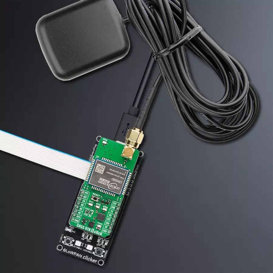
6LoWPAN clicker
Compiler
NECTO Studio
MCU
PIC32MX470F512H
Navigation and positioning with multifrequency GNSS and anti-jamming technology perfect for surveying, agriculture, UAVs, and robotics
A
A
Hardware Overview
How does it work?
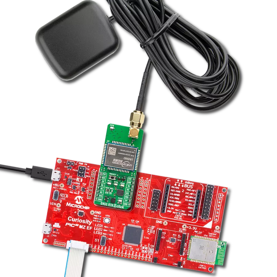
GNSS RTK 5 Click is based on the UM980, an all-constellation multifrequency RTK positioning module from Unicore. The UM980 uses Unicore's NebulasIV SoC, a GNSS System-on-Chip (SoC) that combines RF-baseband integration with advanced high-precision algorithms. This SoC also includes a dual-core CPU, a high-speed floating-point processor, and a dedicated RTK co-processor, supported by 1408 channels, ensuring unparalleled signal processing capabilities. The UM980 supports many satellite constellations, including GPS, BDS, GLONASS, Galileo, QZSS, NavIC, SBAS, and L-Band, making it suitable for global high-precision applications. Its integrated JamShield adaptive anti-jamming technology further enhances signal reliability, offering faster initialization, exceptional measurement accuracy, and unmatched reliability, even in challenging environments such as dense urban landscapes and heavily shaded areas. Thanks to these advanced features, GNSS RTK 5 Click excels in many high-precision navigation and positioning scenarios like surveying and mapping, precision agriculture, unmanned aerial vehicles (UAVs), and autonomous robotics. The UM980 and the host MCU are communicated through a UART interface, using standard UART RX and TX pins for efficient data transfer. The module defaults to a communication speed of 115200bps, allowing for seamless data
exchange over AT commands. While the module also includes pins for an I2C interface, this functionality is currently unsupported in the existing firmware version. In addition to the interface pins, the board features a reset (RST) pin and a RESET button for hard resetting the module when necessary. This board also includes a USB Type-C connector for USB 2.0 Full Speed 12Mbps hardware capability, allowing both power supply and configuration via a PC. This functionality is enabled by the CP2102N, a highly integrated USB-to-UART bridge, along with the MCP1826 LDO regulator, which converts the USB supply to the necessary 3.3V for the module, allowing for standalone configuration. A notable addition to the board is the inclusion of dedicated test points, among which test points 3 and 4 stand out. These represent the module's CAN TX and RX signals, operating at LVTTL levels and offering additional functionality for specific user requirements. The board incorporates several additional pins that enhance functionality and provide real-time status feedback. The PVT pin serves as a position, velocity, and time calculation indicator, remaining HIGH during active positioning, while the ERR pin acts as an error status indicator, showing HIGH when the module fails its self-test and LOW when it passes. Additionally, the EVT pin is used for event mark input, enabling the logging of precise GNSS
time tags. Visual indicators complement these pins for improved usability: the PVT pin is linked to a green LED, and the ERR pin is connected to a red LED, providing immediate visual feedback. The board also features a blue LED to indicate the RTK feature, lighting up HIGH for an RTK fixed solution and LOW for other positioning statuses or no positioning. Furthermore, a yellow LED displays the timepulse signal (PPS), offering precise time synchronization for applications that require it. This Click board™ also features the SMA antenna connector with an impedance of 50Ω, compatible with various antennas available from MIKROE, like the GNSS L1/L5 Band Active Antenna (High and Standard precision) and others, to enhance its connectivity. This Click board™ can operate with both 3.3V and 5V logic voltage levels selected via the VCC SEL jumper. Since the UM980 module operates at 3.3V, a logic-level translator, the TXS0108E is also used for proper operation and an accurate signal-level translation. This way, both 3.3V and 5V capable MCUs can use the communication lines properly. Also, this Click board™ comes equipped with a library containing easy-to-use functions and an example code that can be used as a reference for further development.

Features overview
Development board
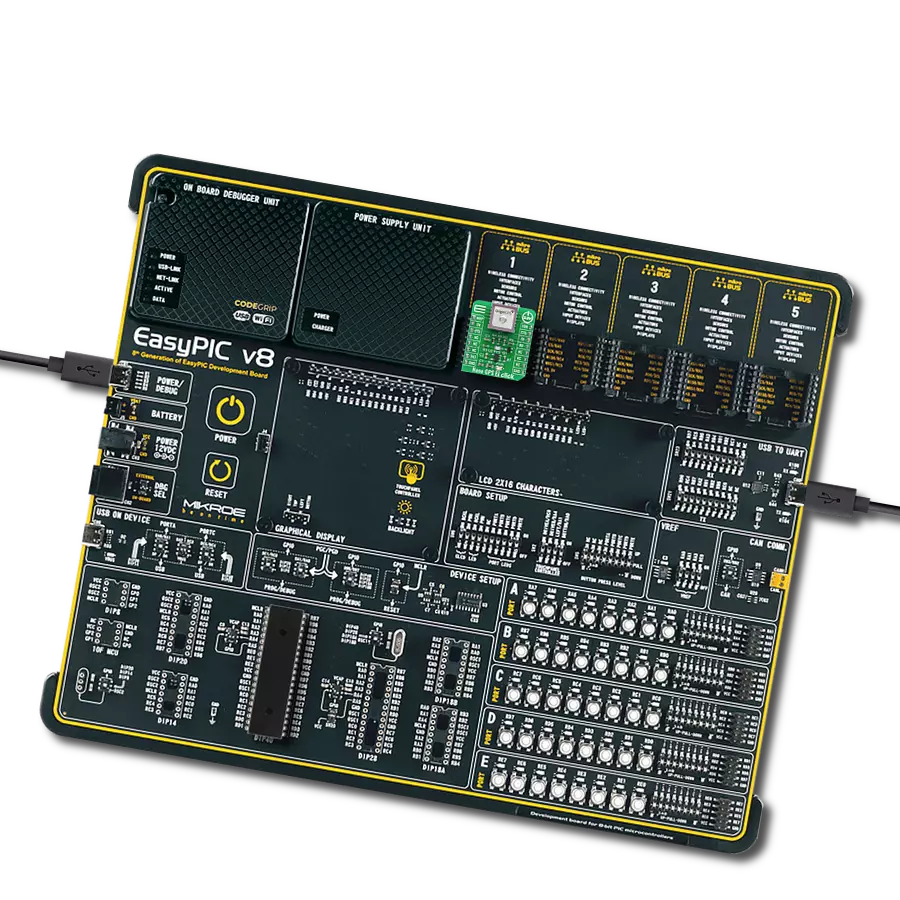
6LoWPAN Clicker is a compact starter development board that brings the flexibility of add-on Click boards™ to your favorite microcontroller, making it a perfect starter kit for implementing your ideas. It comes with an onboard 32-bit PIC microcontroller, the PIC32MX470F512H from Microchip, a USB connector, LED indicators, buttons, a mikroProg connector, and a header for interfacing with external electronics. Along with this microcontroller, the board also contains a 2.4GHz ISM band transceiver, allowing you to add wireless communication to your target application. Its compact design provides a fluid and immersive working experience, allowing access anywhere
and under any circumstances. Each part of the 6LoWPAN Clicker development kit contains the components necessary for the most efficient operation of the same board. In addition to the possibility of choosing the 6LoWPAN Clicker programming method, using USB HID mikroBootloader, or through an external mikroProg connector for PIC, dsPIC, or PIC32 programmer, the Clicker board also includes a clean and regulated power supply module for the development kit. The USB Micro-B connection can provide up to 500mA of current for the Clicker board, which is more than enough to operate all onboard and additional modules, or it can power
over two standard AA batteries. All communication methods that mikroBUS™ itself supports are on this board, including the well-established mikroBUS™ socket, reset button, and several buttons and LED indicators. 6LoWPAN Clicker is an integral part of the Mikroe ecosystem, allowing you to create a new application in minutes. Natively supported by Mikroe software tools, it covers many aspects of prototyping thanks to a considerable number of different Click boards™ (over a thousand boards), the number of which is growing every day.

Microcontroller Overview
MCU Card / MCU

Architecture
PIC32
MCU Memory (KB)
512
Silicon Vendor
Microchip
Pin count
64
RAM (Bytes)
131072
You complete me!
Accessories
GNSS L1/L5 Band Active Antenna - High Precision (ANN-MB1) is a multi-band active antenna designed to support GPS, GLONASS, Galileo, and BeiDou systems, offering a comprehensive solution for high-precision GNSS applications. Optimized for applications demanding exceptional accuracy, this multi-band antenna provides coverage for L1, L5, E5a, B2a, and NavIC frequency bands, ensuring reliable performance across diverse GNSS systems. The ANN-MB1 stands out with its compact design and excellent price-to-performance ratio, making it an ideal choice for users seeking a fast and efficient path to market. This antenna is an excellent companion for the u-blox F9 platform, including models such as NEO-F9P-15B, ZED-F9P15B, and ZED-F9T-10B. By supporting both L1 and L5 bands, the ANN-MB1 streamlines integration efforts, helping users minimize evaluation and design complexities. Its robust design enables superior multi-band operation, which is essential for applications requiring high positional accuracy, such as surveying, precision agriculture, and autonomous navigation systems. At the heart of the ANN-MB1 is a high-performance Right-Hand Circularly Polarized (RHCP) dual-resonance, dual-feed patch antenna element. This sophisticated design is complemented by a built-in high-gain Low-Noise Amplifier (LNA) with Surface Acoustic Wave (SAW) pre-filtering, ensuring optimal signal quality by reducing noise and interference. The integrated LNA significantly enhances the antenna’s ability to capture weak GNSS signals, providing reliable performance even in challenging environments. The ANN-MB1 antenna is equipped with a 5-meter cable terminated with an SMA connector, offering flexibility in placement and ease of installation. Its well-engineered design ensures consistent performance across various applications, making it an invaluable tool for the next generation of GNSS-based systems. With its user-friendly setup and robust performance, the ANN-MB1 is tailored to meet the demands of industries requiring precise and reliable GNSS solutions.

GNSS L1/L5 Band Active Antenna - Standard Precision (ANN-MB5) is a high-performance multi-band active GNSS antenna developed by u-blox for GPS, Galileo, and BeiDou systems. Designed for standard precision applications, this antenna offers exceptional performance at an affordable price, making it an ideal choice for next-generation multi-frequency GNSS technology. The ANN-MB5 supports multiple bands, including L1, L5, E5a, B2a, and NavIC, enabling precise and reliable positioning even in complex and obstructed environments. Engineered for ease of integration, the ANN-MB5 boasts a compact design, simple mounting options, and a cost-effective solution for large-scale deployments. This antenna perfectly suits u-blox’s multi-band GNSS receivers, such as the F10 standard precision platform, ensuring seamless compatibility. Minimizing the need for additional evaluation and design efforts accelerates development timelines and reduces time-to-market. The ANN-MB5 features an advanced multi-band RHCP (Right-Hand Circularly Polarized) single-feed stacked-patch antenna element, providing robust signal reception across multiple GNSS frequencies. It incorporates a built-in low-noise amplifier (LNA) with SAW (Surface Acoustic Wave) pre-filtering to enhance signal quality and reduce interference. The antenna has a 3-meter cable and an SMA connector, offering flexible placement options for diverse application needs. This antenna meets the demands of modern GNSS applications, offering high reliability, accurate positioning, and simplified deployment in a wide range of environments.

Used MCU Pins
mikroBUS™ mapper
Take a closer look
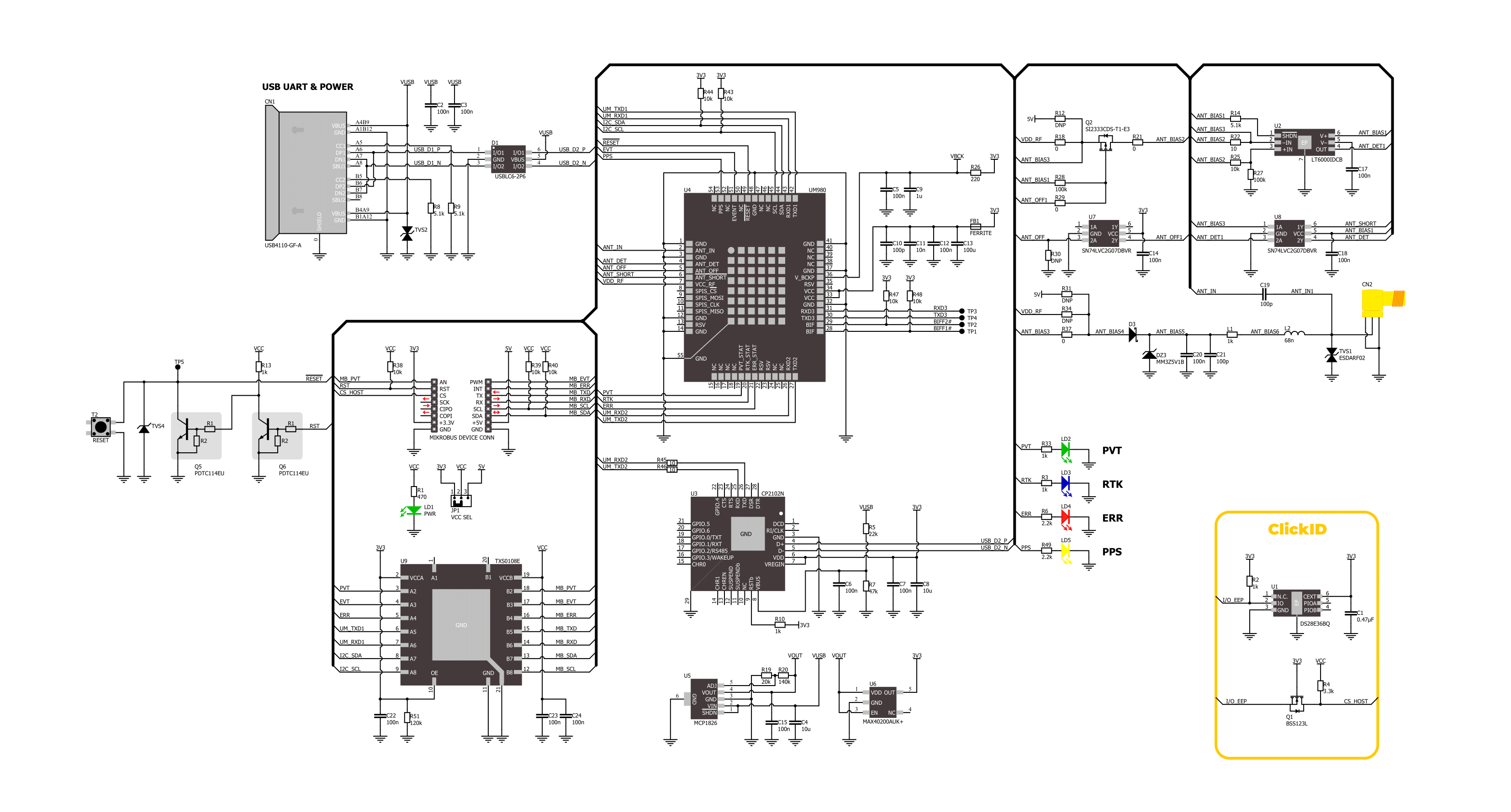
Click board™ Schematic
Step by step
Project assembly

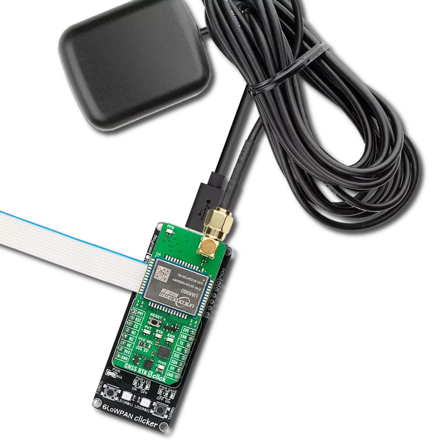
Start by selecting your development board and Click board™. Begin with the 6LoWPAN clicker as your development board.


Track your results in real time
Application Output
1. Application Output - In Debug mode, the 'Application Output' window enables real-time data monitoring, offering direct insight into execution results. Ensure proper data display by configuring the environment correctly using the provided tutorial.

2. UART Terminal - Use the UART Terminal to monitor data transmission via a USB to UART converter, allowing direct communication between the Click board™ and your development system. Configure the baud rate and other serial settings according to your project's requirements to ensure proper functionality. For step-by-step setup instructions, refer to the provided tutorial.

3. Plot Output - The Plot feature offers a powerful way to visualize real-time sensor data, enabling trend analysis, debugging, and comparison of multiple data points. To set it up correctly, follow the provided tutorial, which includes a step-by-step example of using the Plot feature to display Click board™ readings. To use the Plot feature in your code, use the function: plot(*insert_graph_name*, variable_name);. This is a general format, and it is up to the user to replace 'insert_graph_name' with the actual graph name and 'variable_name' with the parameter to be displayed.

Software Support
Library Description
GNSS RTK 5 Click demo application is developed using the NECTO Studio, ensuring compatibility with mikroSDK's open-source libraries and tools. Designed for plug-and-play implementation and testing, the demo is fully compatible with all development, starter, and mikromedia boards featuring a mikroBUS™ socket.
Example Description
This example demonstrates the use of GNSS RTK 5 Click by reading and displaying the GNSS coordinates.
Key functions:
gnssrtk5_cfg_setup- Config Object Initialization function.gnssrtk5_init- Initialization function.gnssrtk5_cmd_run- This function parses the GGA data from the read response buffer.gnssrtk5_parse_gga- This function parses the GGA data from the read response buffer.gnssrtk5_generic_read- This function reads a desired number of data bytes by using UART serial interface.
Application Init
Initializes the driver, resets the Click board, reads the module version and config, and enables the NMEA GNGGA message output.
Application Task
Reads the received data, parses the NMEA GGA info from it, and once it receives the position fix it will start displaying the coordinates on the USB UART.
Open Source
Code example
The complete application code and a ready-to-use project are available through the NECTO Studio Package Manager for direct installation in the NECTO Studio. The application code can also be found on the MIKROE GitHub account.
/*!
 * @file main.c
 * @brief GNSS RTK 5 Click Example.
 *
 * # Description
 * This example demonstrates the use of GNSS RTK 5 Click by reading and displaying
 * the GNSS coordinates.
 *
 * The demo application is composed of two sections :
 *
 * ## Application Init
 * Initializes the driver, resets the Click board, reads the module version and config,
 * and enables the NMEA GNGGA message output.
 *
 * ## Application Task
 * Reads the received data, parses the NMEA GGA info from it, and once it receives
 * the position fix it will start displaying the coordinates on the USB UART.
 *
 * ## Additional Function
 * - static void gnssrtk5_clear_app_buf ( void )
 * - static void gnssrtk5_log_app_buf ( void )
 * - static err_t gnssrtk5_process ( gnssrtk5_t *ctx )
 * - static err_t gnssrtk5_read_response ( gnssrtk5_t *ctx, uint8_t *rsp )
 * - static void gnssrtk5_parser_application ( uint8_t *rsp )
 *
 * @author Stefan Filipovic
 *
 */

#include "board.h"
#include "log.h"
#include "gnssrtk5.h"

// Application buffer size
#define APP_BUFFER_SIZE             800
#define PROCESS_BUFFER_SIZE         100

static gnssrtk5_t gnssrtk5;
static log_t logger;

static uint8_t app_buf[ APP_BUFFER_SIZE ] = { 0 };
static int32_t app_buf_len = 0;

/**
 * @brief GNSS RTK 5 clearing application buffer.
 * @details This function clears memory of application buffer and reset its length.
 * @note None.
 */
static void gnssrtk5_clear_app_buf ( void );

/**
 * @brief GNSS RTK 5 log application buffer.
 * @details This function logs data from application buffer to USB UART.
 * @note None.
 */
static void gnssrtk5_log_app_buf ( void );

/**
 * @brief GNSS RTK 5 data reading function.
 * @details This function reads data from device and concatenates data to application buffer.
 * @param[in] ctx : Click context object.
 * See #gnssrtk5_t object definition for detailed explanation.
 * @return @li @c  0 - Read some data.
 *         @li @c -1 - Nothing is read.
 * See #err_t definition for detailed explanation.
 * @note None.
 */
static err_t gnssrtk5_process ( gnssrtk5_t *ctx );

/**
 * @brief GNSS RTK 5 read response function.
 * @details This function waits for a response message, reads and displays it on the USB UART.
 * @param[in] ctx : Click context object.
 * See #gnssrtk5_t object definition for detailed explanation.
 * @param[in] rsp  Expected response.
 * @return @li @c  0 - OK response.
 *         @li @c -2 - Timeout error.
 * See #err_t definition for detailed explanation.
 * @note None.
 */
static err_t gnssrtk5_read_response ( gnssrtk5_t *ctx, uint8_t *rsp );

/**
 * @brief GNSS RTK 5 parser application.
 * @param[in] rsp Response buffer.
 * @details This function logs GNSS data on the USB UART.
 * @return None.
 * @note None.
 */
static void gnssrtk5_parser_application ( uint8_t *rsp );

void application_init ( void )
{
    log_cfg_t log_cfg;  /**< Logger config object. */
    gnssrtk5_cfg_t gnssrtk5_cfg;  /**< Click config object. */

    /**
     * Logger initialization.
     * Default baud rate: 115200
     * Default log level: LOG_LEVEL_DEBUG
     * @note If USB_UART_RX and USB_UART_TX
     * are defined as HAL_PIN_NC, you will
     * need to define them manually for log to work.
     * See @b LOG_MAP_USB_UART macro definition for detailed explanation.
     */
    LOG_MAP_USB_UART( log_cfg );
    log_init( &logger, &log_cfg );
    log_info( &logger, " Application Init " );

    // Click initialization.
    gnssrtk5_cfg_setup( &gnssrtk5_cfg );
    GNSSRTK5_MAP_MIKROBUS( gnssrtk5_cfg, MIKROBUS_1 );
    if ( UART_ERROR == gnssrtk5_init( &gnssrtk5, &gnssrtk5_cfg ) )
    {
        log_error( &logger, " Communication init." );
        for ( ; ; );
    }

    log_printf( &logger, ">>> Reset device.\r\n" );
    gnssrtk5_reset_device ( &gnssrtk5 );
    gnssrtk5_read_response ( &gnssrtk5, GNSSRTK5_RSP_RESET );

    log_printf( &logger, ">>> Get module version.\r\n" );
    gnssrtk5_cmd_run ( &gnssrtk5, GNSSRTK5_CMD_GET_VERSION );
    gnssrtk5_read_response ( &gnssrtk5, GNSSRTK5_RSP_COMMAND );

    log_printf( &logger, ">>> Get module config.\r\n" );
    gnssrtk5_cmd_run ( &gnssrtk5, GNSSRTK5_CMD_GET_CONFIG );
    gnssrtk5_read_response ( &gnssrtk5, GNSSRTK5_RSP_COMMAND );

    log_printf( &logger, ">>> Enable GNGGA output.\r\n" );
    gnssrtk5_cmd_run ( &gnssrtk5, GNSSRTK5_CMD_ENABLE_GGA );
    gnssrtk5_read_response ( &gnssrtk5, GNSSRTK5_RSP_COMMAND );
    gnssrtk5_clear_app_buf( );

    log_info( &logger, " Application Task " );
}

void application_task ( void )
{
    if ( GNSSRTK5_OK == gnssrtk5_process( &gnssrtk5 ) )
    {
        if ( app_buf_len > ( sizeof ( GNSSRTK5_RSP_GGA ) + GNSSRTK5_GGA_ELEMENT_SIZE ) )
        {
            gnssrtk5_parser_application( app_buf );
        }
    }
}

int main ( void )
{
    /* Do not remove this line or clock might not be set correctly. */
    #ifdef PREINIT_SUPPORTED
    preinit();
    #endif

    application_init( );

    for ( ; ; )
    {
        application_task( );
    }

    return 0;
}

static void gnssrtk5_clear_app_buf ( void )
{
    memset( app_buf, 0, app_buf_len );
    app_buf_len = 0;
}

static void gnssrtk5_log_app_buf ( void )
{
    for ( int32_t buf_cnt = 0; buf_cnt < app_buf_len; buf_cnt++ )
    {
        log_printf( &logger, "%c", app_buf[ buf_cnt ] );
    }
}

static err_t gnssrtk5_process ( gnssrtk5_t *ctx )
{
    uint8_t rx_buf[ PROCESS_BUFFER_SIZE ] = { 0 };
    int32_t overflow_bytes = 0;
    int32_t rx_cnt = 0;
    int32_t rx_size = gnssrtk5_generic_read( ctx, rx_buf, PROCESS_BUFFER_SIZE );
    if ( ( rx_size > 0 ) && ( rx_size <= APP_BUFFER_SIZE ) )
    {
        if ( ( app_buf_len + rx_size ) > APP_BUFFER_SIZE )
        {
            overflow_bytes = ( app_buf_len + rx_size ) - APP_BUFFER_SIZE;
            app_buf_len = APP_BUFFER_SIZE - rx_size;
            memmove ( app_buf, &app_buf[ overflow_bytes ], app_buf_len );
            memset ( &app_buf[ app_buf_len ], 0, overflow_bytes );
        }
        for ( rx_cnt = 0; rx_cnt < rx_size; rx_cnt++ )
        {
            if ( rx_buf[ rx_cnt ] )
            {
                app_buf[ app_buf_len++ ] = rx_buf[ rx_cnt ];
            }
        }
        return GNSSRTK5_OK;
    }
    return GNSSRTK5_ERROR;
}

static err_t gnssrtk5_read_response ( gnssrtk5_t *ctx, uint8_t *rsp )
{
    #define READ_RESPONSE_TIMEOUT_MS 5000
    uint32_t timeout_cnt = 0;
    gnssrtk5_clear_app_buf ( );
    while ( ( GNSSRTK5_OK == gnssrtk5_process( ctx ) ) || ( 0 == strstr( app_buf, rsp ) ) )
    {
        if ( timeout_cnt > READ_RESPONSE_TIMEOUT_MS )
        {
            gnssrtk5_log_app_buf( );
            gnssrtk5_clear_app_buf( );
            log_error( &logger, " Timeout!" );
            return GNSSRTK5_ERROR_TIMEOUT;
        }
        timeout_cnt += 10;
        Delay_ms( 10 );
    }
    gnssrtk5_log_app_buf( );
    log_printf( &logger, "--------------------------------\r\n" );
    return GNSSRTK5_OK;
}

static void gnssrtk5_parser_application ( uint8_t *rsp )
{
    uint8_t element_buf[ PROCESS_BUFFER_SIZE ] = { 0 };
    if ( GNSSRTK5_OK == gnssrtk5_parse_gga( rsp, GNSSRTK5_GGA_LATITUDE, element_buf ) )
    {
        static uint8_t wait_for_fix_cnt = 0;
        if ( strlen( element_buf ) > 0 )
        {
            log_printf( &logger, "\r\n Latitude: %.2s degrees, %s minutes \r\n", element_buf, &element_buf[ 2 ] );
            memset( element_buf, 0, sizeof( element_buf ) );
            gnssrtk5_parse_gga( rsp, GNSSRTK5_GGA_LONGITUDE, element_buf );
            log_printf( &logger, " Longitude: %.3s degrees, %s minutes \r\n", element_buf, &element_buf[ 3 ] );
            memset( element_buf, 0, sizeof( element_buf ) );
            gnssrtk5_parse_gga( rsp, GNSSRTK5_GGA_ALTITUDE, element_buf );
            log_printf( &logger, " Altitude: %s m \r\n", element_buf );
            wait_for_fix_cnt = 0;
        }
        else
        {
            if ( wait_for_fix_cnt % 5 == 0 )
            {
                log_printf( &logger, " Waiting for the position fix...\r\n\n" );
                wait_for_fix_cnt = 0;
            }
            wait_for_fix_cnt++;
        }
        gnssrtk5_clear_app_buf(  );
    }
}

// ------------------------------------------------------------------------ END
Additional Support
Resources
Category:GPS/GNSS