Achieve a smooth and dependable connection to the Click Cloud with ESP-WROOM-02 and TM4C129ENCPDT
Gateway to Click Cloud: Where ideas take shape!

Published Nov 09, 2023
Click board™
Go to Cloud (G2C) Click
Dev. board
Fusion for Tiva v8
Compiler
NECTO Studio
MCU
TM4C129ENCPDT
Experience innovation at its finest with our gateway solution, connecting you securely to Click Cloud, the ideal playground for turning your ideas into reality.
A
A
Hardware Overview
How does it work?
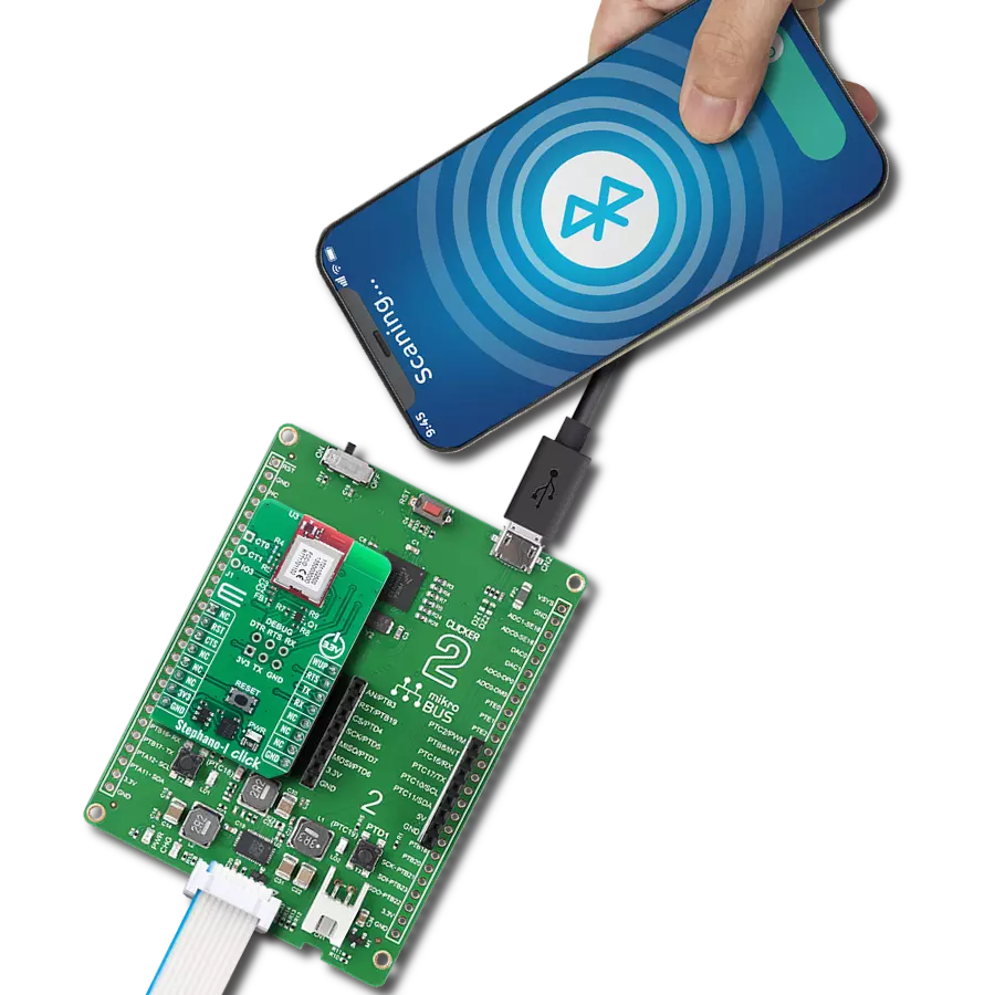
Go to Cloud (G2C) Click is a Click board™ which allows connection to the feature-rich Click Cloud platform, over the WiFi network. Go to Cloud (G2C) click is envisioned so that users can easily add cloud connectivity and develop their own cloud-based applications, using only a set of simple AT commands, without having to delve into the complexity of web, hardware, and communications related development. Thanks to this simplified approach, everyone can benefit using the Click Cloud solution with Go to Cloud (G2C) click, since this Click board™ has all the necessary protocol and communication settings already implemented within its firmware. This saves a lot of time that would be otherwise wasted on the firmware development, and to adapting it to work with some third-party solution. Not to mention that such an effort would also require embedded and web programming proficiency, along with several other engineering skills. G2C click, on the other hand, works in unity with Click Cloud solution, right out of the box. Go to Cloud (G2C)
click performs several tasks on its side, which are required to connect to the Click Cloud platform. To establish the connection, an access to a WiFi network with Internet connectivity is required. For a reliable WiFi network connection, the Click board™ utilizes the ESP WROOM-02 WiFi module, a well-established integrated WiFi solution. The Click board™ uses a powerful MCU to manage the connection parameters, initialize the ESP-WROOM-02 WiFi module, and establish the connection with the Click Cloud platform. This allows to set up the connection in just a few simple steps, issuing a set of short AT commands, such as the SSID, password, device_ID, and so on. The complete documentation with in-depth explanation of each AT command and its response can be found in the AT Command Manual. Besides the AT commands that are used to set up basic connection parameters, there are also AT commands that allow storing of the connection parameters, including the connection password, network SSID, device_ID, and
other relevant connection data. These parameters can be stored in the non-volatile memory of the Go to Cloud (G2C) click. It is possible to restore them by a single macro command, resulting in a very simplified connection procedure. The functionality of the Go to Cloud (G2C) click will be constantly improved in the future. Therefore, Go to Cloud (G2C) click supports an upgrade of its firmware over the onboard USB connector. The firmware update process is very simple, using the familiar "HID Bootloader" software tool from MikroElektronika. Go to Cloud (G2C) click is equipped with four LED indicators. They are used to indicate the presence of a power supply, the WiFi network connection, the USB connection, and the connection with the Click Cloud solution. These LEDs provide visual feedback about the status of the Go to Cloud (G2C) click. This Click board™ requires both 3.3V and 5V power rails for proper operation.

Features overview
Development board
Fusion for TIVA v8 is a development board specially designed for the needs of rapid development of embedded applications. It supports a wide range of microcontrollers, such as different 32-bit ARM® Cortex®-M based MCUs from Texas Instruments, regardless of their number of pins, and a broad set of unique functions, such as the first-ever embedded debugger/programmer over a WiFi network. The development board is well organized and designed so that the end-user has all the necessary elements, such as switches, buttons, indicators, connectors, and others, in one place. Thanks to innovative manufacturing technology, Fusion for TIVA v8 provides a fluid and immersive working experience, allowing access
anywhere and under any circumstances at any time. Each part of the Fusion for TIVA v8 development board contains the components necessary for the most efficient operation of the same board. An advanced integrated CODEGRIP programmer/debugger module offers many valuable programming/debugging options, including support for JTAG, SWD, and SWO Trace (Single Wire Output)), and seamless integration with the Mikroe software environment. Besides, it also includes a clean and regulated power supply module for the development board. It can use a wide range of external power sources, including a battery, an external 12V power supply, and a power source via the USB Type-C (USB-C) connector.
Communication options such as USB-UART, USB HOST/DEVICE, CAN (on the MCU card, if supported), and Ethernet is also included. In addition, it also has the well-established mikroBUS™ standard, a standardized socket for the MCU card (SiBRAIN standard), and two display options for the TFT board line of products and character-based LCD. Fusion for TIVA v8 is an integral part of the Mikroe ecosystem for rapid development. Natively supported by Mikroe software tools, it covers many aspects of prototyping and development thanks to a considerable number of different Click boards™ (over a thousand boards), the number of which is growing every day.

Microcontroller Overview
MCU Card / MCU

Type
8th Generation
Architecture
ARM Cortex-M4
MCU Memory (KB)
1024
Silicon Vendor
Texas Instruments
Pin count
128
RAM (Bytes)
262144
Used MCU Pins
mikroBUS™ mapper
Take a closer look
Click board™ Schematic

Step by step
Project assembly

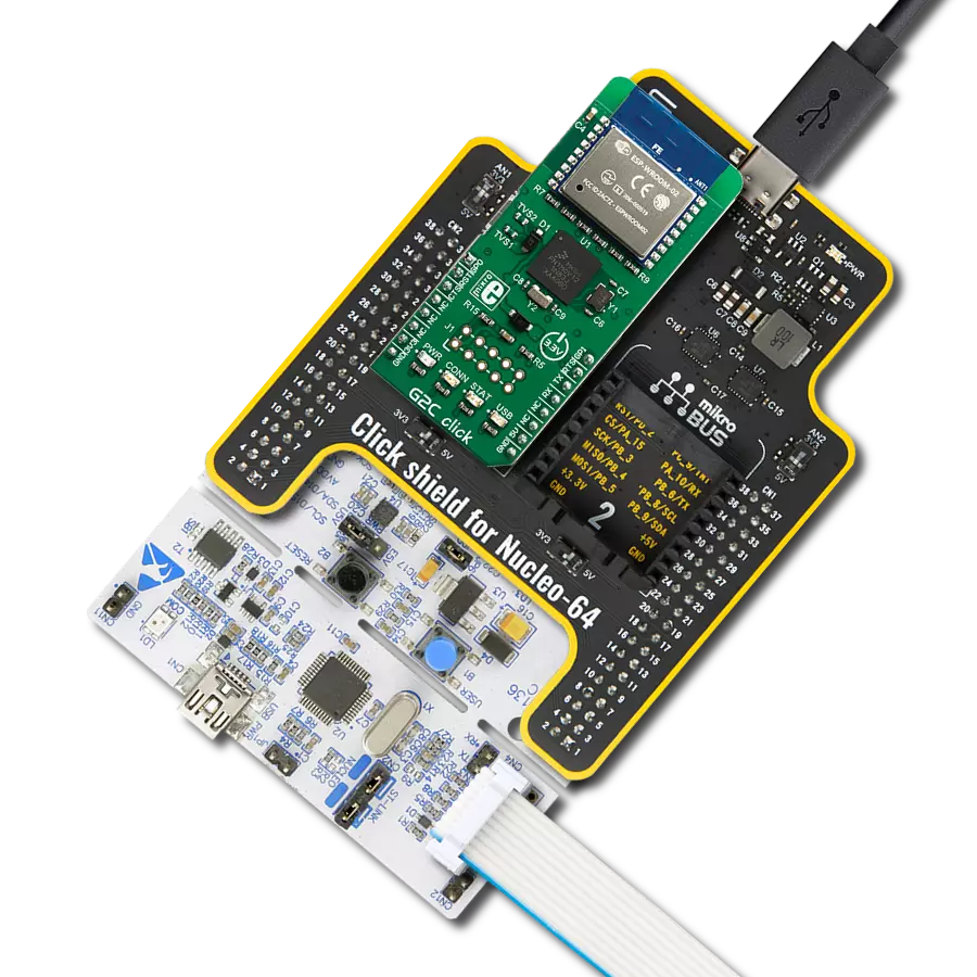
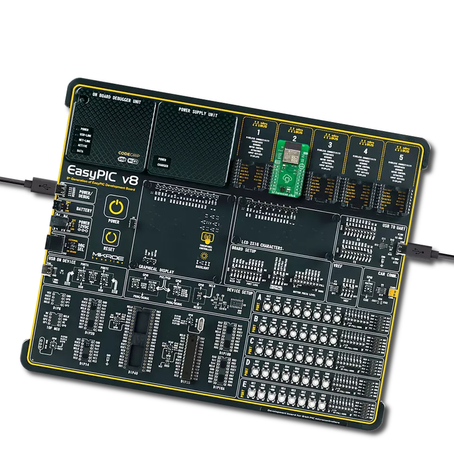
Start by selecting your development board and Click board™. Begin with the Fusion for Tiva v8 as your development board.


Software Support
Library Description
This library contains API for Go to Cloud (G2C) Click driver.
Key functions:
g2c_reset_device- This function resets the device by toggling the RST pin.g2c_set_net_creds- This function sets the WiFi network credentials.g2c_set_broker_creds- This function sets the broker credentials (device key and password).
Open Source
Code example
The complete application code and a ready-to-use project are available through the NECTO Studio Package Manager for direct installation in the NECTO Studio. The application code can also be found on the MIKROE GitHub account.
/*!
 * @file main.c
 * @brief G2C Click Example.
 *
 * # Description
 * This example shows the device capability of connecting to the cloud and
 * updating the sensor data on the cloud and receiving data from actuators.
 *
 * The demo application is composed of two sections :
 *
 * ## Application Init
 * Initializes the driver, restarts the device, and after that tests
 * the communication by sending "AT" command.
 *
 * ## Application Task
 * Application task is split in few stages:
 *  - G2C_CONNECT_TO_NETWORK:
 * Sends commands to configure device to connect to the specified network.
 *
 *  - G2C_CONNECT_TO_CLOUD:
 * Sends commands to configure device to connect to the specified device on the cloud.
 *
 *  - G2C_EXAMPLE:
 * This function executes example which updates sensor data on the cloud and displays
 * all data received from the module (ex. the actuator switch state change received
 * from the cloud).
 *
 * ## Additional Function
 * - static void g2c_clear_app_buf ( void )
 * - static err_t g2c_process ( void )
 * - static void g2c_error_check( err_t error_flag )
 * - static void g2c_log_app_buf ( void )
 * - static err_t g2c_rsp_check ( uint8_t *rsp )
 * - static err_t g2c_connect_to_network( void )
 * - static err_t g2c_connect_to_cloud( void )
 * - static err_t g2c_example( void )
 *
 * @note
 * In order for the example to work, user needs to set the WiFi credentials and the cloud device parameters.
 * Enter valid values for the following macros:
 * WIFI_SSID, WIFI_PASS, DEVICE_KEY, DEVICE_PASSWORD, DEVICE_SENSOR_REF.
 * Example:
 * WIFI_SSID            "MikroE Public"
 * WIFI_PASS            "mikroe.guest"
 * DEVICE_KEY           "xxxxxxxxxxxxxxxx"
 * DEVICE_PASSWORD      "xxxxxxxx-xxxx-xxxx-xxxx-xxxxxxxxxxxx"
 * DEVICE_SENSOR_REF    "TEMP_SEN_R"
 *
 * DEVICE_KEY and DEVICE_PASSWORD strings should match the device credentials which
 * were generated during the Click Cloud device creation step.
 * DEVICE_SENSOR_REF is expected to be a reference to a temperature sensor with a data
 * range from -20 to +80 degrees Celsius.
 * For more information about the registration on the Click Cloud and creating the device
 * refer to the following user guide:
 * https://download.mikroe.com/documents/click-cloud/guide-to-click-cloud.pdf
 *
 * @author Stefan Filipovic
 *
 */

#include "board.h"
#include "log.h"
#include "g2c.h"
#include "conversions.h"

// Network config parameters
#define WIFI_SSID                           "MikroE Public"  // Set valid WiFi SSID
#define WIFI_PASS                           "mikroe.guest"   // Set valid WiFi Password

// Cloud device config parameters
#define DEVICE_KEY                          ""  // Cloud device key
#define DEVICE_PASSWORD                     ""  // Cloud device password
#define DEVICE_SENSOR_REF                   ""  // Cloud device sensor reference

// Application buffer size
#define APP_BUFFER_SIZE                     300
#define PROCESS_BUFFER_SIZE                 300

/**
 * @brief Example states.
 * @details Predefined enum values for application example state.
 */
typedef enum
{
    G2C_CONNECT_TO_NETWORK = 1,
    G2C_CONNECT_TO_CLOUD,
    G2C_EXAMPLE

} g2c_example_state_t;

static g2c_t g2c;
static log_t logger;

/**
 * @brief Application example variables.
 * @details Variables used in application example.
 */
static uint8_t app_buf[ PROCESS_BUFFER_SIZE ] = { 0 };
static int32_t app_buf_len = 0;
static err_t error_flag;
static g2c_example_state_t example_state;

/**
 * @brief G2C clearing application buffer.
 * @details This function clears memory of application buffer and reset its length.
 * @note None.
 */
static void g2c_clear_app_buf ( void );

/**
 * @brief G2C data reading function.
 * @details This function reads data from device and concatenates data to application buffer.
 * @return @li @c  0 - Read some data.
 *         @li @c -1 - Nothing is read.
 * See #err_t definition for detailed explanation.
 * @note None.
 */
static err_t g2c_process ( void );

/**
 * @brief Check for errors.
 * @details This function checks for different types of
 * errors and logs them on UART or logs the response if no errors occured.
 * @param[in] error_flag  Error flag to check.
 */
static void g2c_error_check ( err_t error_flag );

/**
 * @brief Logs application buffer.
 * @details This function logs data from application buffer.
 */
static void g2c_log_app_buf ( void );

/**
 * @brief Response check.
 * @details This function checks for response and returns the status of response.
 * @param[in] rsp  Expected response.
 * @return @li @c  0 - OK response.
 *         @li @c -2 - Timeout error.
 *         @li @c -3 - Command error.
 *         @li @c -4 - Unknown error.
 * See #err_t definition for detailed explanation.
 */
static err_t g2c_rsp_check ( uint8_t *rsp );

/**
 * @brief Configure device to connect to the network.
 * @details Sends commands to configure device to connect to the specified network.
 * @return @li @c  0 - OK response.
 *         @li @c -2 - Timeout error.
 *         @li @c -3 - Command error.
 *         @li @c -4 - Unknown error.
 * See #err_t definition for detailed explanation.
 */
static err_t g2c_connect_to_network ( void );

/**
 * @brief Configure device to connect to the cloud.
 * @details Sends commands to configure device to connect to the specified device on the cloud.
 * @return @li @c  0 - OK response.
 *         @li @c -2 - Timeout error.
 *         @li @c -3 - Command error.
 *         @li @c -4 - Unknown error.
 * See #err_t definition for detailed explanation.
 */
static err_t g2c_connect_to_cloud ( void );

/**
 * @brief Execute example.
 * @details This function executes example which updates sensor data on the cloud and displays
 * all data received from the module (ex. the actuator state change received from the cloud).
 * @return @li @c  0 - OK response.
 *         @li @c -2 - Timeout error.
 *         @li @c -3 - Command error.
 *         @li @c -4 - Unknown error.
 * See #err_t definition for detailed explanation.
 */
static err_t g2c_example ( void );

void application_init ( void )
{
    log_cfg_t log_cfg;  /**< Logger config object. */
    g2c_cfg_t g2c_cfg;  /**< Click config object. */

    /**
     * Logger initialization.
     * Default baud rate: 115200
     * Default log level: LOG_LEVEL_DEBUG
     * @note If USB_UART_RX and USB_UART_TX
     * are defined as HAL_PIN_NC, you will
     * need to define them manually for log to work.
     * See @b LOG_MAP_USB_UART macro definition for detailed explanation.
     */
    LOG_MAP_USB_UART( log_cfg );
    log_init( &logger, &log_cfg );
    log_info( &logger, " Application Init " );

    // Click initialization.
    g2c_cfg_setup( &g2c_cfg );
    G2C_MAP_MIKROBUS( g2c_cfg, MIKROBUS_1 );
    if ( UART_ERROR == g2c_init( &g2c, &g2c_cfg ) )
    {
        log_error( &logger, " Communication init." );
        for ( ; ; );
    }

    // Clear RX buffer
    g2c_process( );
    g2c_clear_app_buf( );
    Delay_ms ( 100 );

    // Reset device
    g2c_reset_device ( &g2c );

    // Check communication
    log_printf( &logger, "Test communication\r\n" );
    Delay_ms ( 100 );
    g2c_send_cmd( &g2c, G2C_CMD_AT );
    error_flag = g2c_rsp_check( G2C_RSP_OK );
    g2c_error_check( error_flag );

    // Enable command echo
    log_printf( &logger, "Enable echo\r\n" );
    Delay_ms ( 100 );
    g2c_send_cmd( &g2c, G2C_CMD_ATE1 );
    error_flag = g2c_rsp_check( G2C_RSP_OK );
    g2c_error_check( error_flag );

    log_info( &logger, " Application Task " );
    example_state = G2C_CONNECT_TO_NETWORK;
}

void application_task ( void )
{
    switch ( example_state )
    {
        case G2C_CONNECT_TO_NETWORK:
        {
            if ( G2C_OK == g2c_connect_to_network( ) )
            {
                example_state = G2C_CONNECT_TO_CLOUD;
            }
            break;
        }
        case G2C_CONNECT_TO_CLOUD:
        {
            if ( G2C_OK == g2c_connect_to_cloud( ) )
            {
                example_state = G2C_EXAMPLE;
            }
            break;
        }
        case G2C_EXAMPLE:
        {
            g2c_example( );
            break;
        }
        default:
        {
            log_error( &logger, " Example state." );
            break;
        }
    }
}

int main ( void )
{
    /* Do not remove this line or clock might not be set correctly. */
    #ifdef PREINIT_SUPPORTED
    preinit();
    #endif

    application_init( );

    for ( ; ; )
    {
        application_task( );
    }

    return 0;
}

static void g2c_clear_app_buf ( void )
{
    memset( app_buf, 0, app_buf_len );
    app_buf_len = 0;
}

static err_t g2c_process ( void )
{
    uint8_t rx_buf[ PROCESS_BUFFER_SIZE ] = { 0 };
    int32_t rx_size = 0;
    rx_size = g2c_generic_read( &g2c, rx_buf, PROCESS_BUFFER_SIZE );
    if ( rx_size > 0 )
    {
        int32_t buf_cnt = app_buf_len;
        if ( ( ( app_buf_len + rx_size ) > PROCESS_BUFFER_SIZE ) && ( app_buf_len > 0 ) )
        {
            buf_cnt = PROCESS_BUFFER_SIZE - ( ( app_buf_len + rx_size ) - PROCESS_BUFFER_SIZE );
            memmove ( app_buf, &app_buf[ PROCESS_BUFFER_SIZE - buf_cnt ], buf_cnt );
        }
        for ( int32_t rx_cnt = 0; rx_cnt < rx_size; rx_cnt++ )
        {
            if ( rx_buf[ rx_cnt ] )
            {
                app_buf[ buf_cnt++ ] = rx_buf[ rx_cnt ];
                if ( app_buf_len < PROCESS_BUFFER_SIZE )
                {
                    app_buf_len++;
                }
            }
        }
        return G2C_OK;
    }
    return G2C_ERROR;
}

static err_t g2c_rsp_check ( uint8_t *rsp )
{
    uint32_t timeout_cnt = 0;
    uint32_t timeout = 120000;
    g2c_clear_app_buf( );
    g2c_process( );
    while ( ( 0 == strstr( app_buf, rsp ) ) &&
            ( 0 == strstr( app_buf, G2C_RSP_ERROR ) ) )
    {
        g2c_process( );
        if ( timeout_cnt++ > timeout )
        {
            g2c_clear_app_buf( );
            return G2C_ERROR_TIMEOUT;
        }
        Delay_ms ( 1 );
    }
    Delay_ms ( 100 );
    g2c_process( );
    if ( strstr( app_buf, rsp ) )
    {
        return G2C_OK;
    }
    else if ( strstr( app_buf, G2C_RSP_ERROR ) )
    {
        return G2C_ERROR_CMD;
    }
    else
    {
        return G2C_ERROR_UNKNOWN;
    }
}

static void g2c_error_check ( err_t error_flag )
{
    switch ( error_flag )
    {
        case G2C_OK:
        {
            g2c_log_app_buf( );
            break;
        }
        case G2C_ERROR:
        {
            log_error( &logger, " Overflow!" );
            break;
        }
        case G2C_ERROR_TIMEOUT:
        {
            log_error( &logger, " Timeout!" );
            break;
        }
        case G2C_ERROR_CMD:
        {
            log_error( &logger, " CMD!" );
            break;
        }
        case G2C_ERROR_UNKNOWN:
        default:
        {
            log_error( &logger, " Unknown!" );
            break;
        }
    }
    Delay_ms ( 500 );
}

static void g2c_log_app_buf ( void )
{
    for ( int32_t buf_cnt = 0; buf_cnt < app_buf_len; buf_cnt++ )
    {
        log_printf( &logger, "%c", app_buf[ buf_cnt ] );
    }
}

static err_t g2c_connect_to_network ( void )
{
    err_t func_error = G2C_OK;
    Delay_ms ( 500 );

    // Enable connector module
    #define ENABLE_CONNECTOR_MODULE "1"
    g2c_send_cmd_with_par( &g2c, G2C_CMD_CEN, ENABLE_CONNECTOR_MODULE );
    error_flag = g2c_rsp_check( G2C_RSP_OK );
    func_error |= error_flag;
    g2c_error_check( error_flag );

    // Enable DHCP
    #define ENABLE_DHCP "1"
    g2c_send_cmd_with_par( &g2c, G2C_CMD_NWP, ENABLE_DHCP );
    error_flag = g2c_rsp_check( G2C_RSP_OK );
    func_error |= error_flag;
    g2c_error_check( error_flag );

    // Set network credentials
    g2c_set_net_creds( &g2c, WIFI_SSID, WIFI_PASS );
    error_flag = g2c_rsp_check( G2C_RSP_OK );
    func_error |= error_flag;
    g2c_error_check( error_flag );

    // Connect to network
    #define CONNECT_TO_NETWORK "1"
    g2c_send_cmd_with_par( &g2c, G2C_CMD_NWC, CONNECT_TO_NETWORK );
    error_flag = g2c_rsp_check( G2C_RSP_OK );
    func_error |= error_flag;
    g2c_error_check( error_flag );

    Delay_ms ( 1000 );
    Delay_ms ( 1000 );
    Delay_ms ( 1000 );
    Delay_ms ( 1000 );
    Delay_ms ( 1000 );
    return func_error;
}

static err_t g2c_connect_to_cloud ( void )
{
    err_t func_error = G2C_OK;
    Delay_ms ( 500 );

    g2c_set_broker_creds( &g2c, DEVICE_KEY, DEVICE_PASSWORD );
    error_flag = g2c_rsp_check( G2C_RSP_OK );
    func_error |= error_flag;
    g2c_error_check( error_flag );

    // Connect to broker
    #define CONNECT_TO_BROKER "1"
    g2c_send_cmd_with_par( &g2c, G2C_CMD_BRC, CONNECT_TO_BROKER );
    error_flag = g2c_rsp_check( G2C_RSP_OK );
    func_error |= error_flag;
    g2c_error_check( error_flag );

    Delay_ms ( 1000 );
    Delay_ms ( 1000 );
    Delay_ms ( 1000 );
    Delay_ms ( 1000 );
    Delay_ms ( 1000 );
    return func_error;
}

static err_t g2c_example ( void )
{
    err_t func_error = G2C_OK;

    #define ACTUATOR_WAIT_TIME_MS   10000 // This setting also affects the sensor data update rate
    #define TEMPERATURE_MIN        -20
    #define TEMPERATURE_MAX         80
    #define TEMPERATURE_STEP        5
    static int8_t temperature = TEMPERATURE_MIN;
    uint8_t cmd_buf[ 100 ] = { 0 };
    uint8_t temperature_buf[ 10 ] = { 0 };
    uint8_t cmd_separator[ 2 ] = { ',', 0 };
    uint8_t quote_mark[ 2 ] = { '\"', 0 };

    int8_to_str( temperature, temperature_buf );
    l_trim( temperature_buf );
    r_trim( temperature_buf );

    // Store data to the internal memory.
    strcpy( cmd_buf, quote_mark );
    strcat( cmd_buf, DEVICE_SENSOR_REF );
    strcat( cmd_buf, quote_mark );
    strcat( cmd_buf, cmd_separator );
    strcat( cmd_buf, quote_mark );
    strcat( cmd_buf, temperature_buf );
    strcat( cmd_buf, quote_mark );
    g2c_send_cmd_with_par( &g2c, G2C_CMD_DSET, cmd_buf );
    error_flag = g2c_rsp_check( G2C_RSP_OK );
    func_error |= error_flag;
    g2c_error_check( error_flag );
    Delay_ms ( 500 );

    // Publish data to the cloud
    g2c_send_cmd( &g2c, G2C_CMD_PUB );
    error_flag = g2c_rsp_check( G2C_RSP_OK );
    func_error |= error_flag;
    g2c_error_check( error_flag );
    g2c_clear_app_buf( );

    temperature += TEMPERATURE_STEP;
    if ( temperature > TEMPERATURE_MAX )
    {
        temperature = TEMPERATURE_MIN;
    }

    // Check for the actuator response
    for ( uint32_t act_wait_cnt = 0; act_wait_cnt < ACTUATOR_WAIT_TIME_MS; act_wait_cnt++ )
    {
        g2c_process ( );
        if ( app_buf_len )
        {
            g2c_log_app_buf ( );
            g2c_clear_app_buf ( );
        }
        Delay_1ms ( );
    }

    return func_error;
}

// ------------------------------------------------------------------------ END
Additional Support
Resources
Category:WiFi