Monitor pH in various samples for diagnostic insights with MCP607 and STM32F302VC
Decode the secrets of acidity and alkalinity
Published Jul 22, 2025
Click board™
pH 2 Click
Dev. board
CLICKER 4 for STM32F302VCT6
Compiler
NECTO Studio
MCU
STM32F302VC
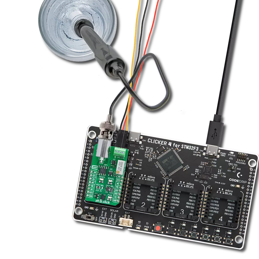
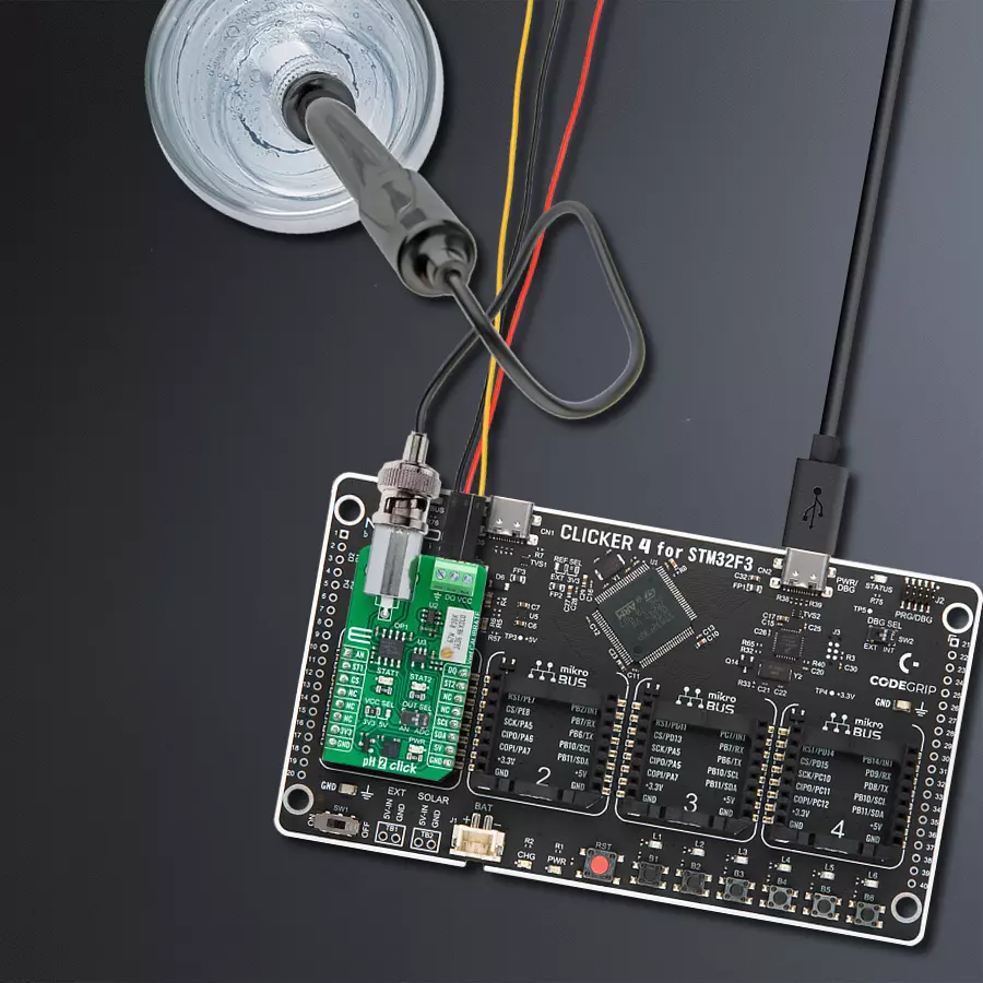
With a solution like this one designed to determine the acidity or alkalinity of a sample, measured using the pH electrode, you can embark on various applications and activities across different industries and fields
A
A
Hardware Overview
How does it work?
pH 2 Click is based on the MCP607, a low-bias current operational amplifier from Microchip. This Click board™ operation is based on measuring hydrogen ion activity and produces an electrical potential or voltage. An electric potential develops when two liquids of different pH come into contact at opposite sides of a pH electrode thin glass membrane. The pH electrode represents a passive sensor, which means no excitation source (voltage or current) is required. It is classified as a bipolar sensor because its output can swing above and below the reference point. This board is a perfect solution for a wide variety of pH-sensing applications, including water treatment, chemical processing, medical instrumentation, and environmental test systems. pH 2 Click is used to detect the concentration of hydrogen ions in a solution and convert it into a corresponding
usable output signal. Because the pH electrode produces a bipolar signal, the electrode signal is first level shifted by the MCP607, a low bias current Op Amp set up in a unity-gain configuration with configurable reference for its calibration. Second, due to the high impedance of the electrode, another Op Amp inside the MCP607 provides the required high-input impedance buffer. A buffered signal can be then converted to a digital value using the MCP3221, a successive approximation A/D converter with a 12-bit resolution from Microchip using a 2-wire I2C compatible interface, or can be sent directly to an analog pin of the mikroBUS™ socket labeled as AN. The selection can be performed using an onboard SMD switch labeled OUT SEL, placing it in an appropriate position marked as AN or ADC. It is important to note that a pH electrode's sensitivity varies over
temperature. For this reason, it is possible to add the DS18B20, 1-wire thermometer via the DQ terminal to the pH 2 Click, whose temperature can be monitored via the DQ pin on the mikroBUS™ socket. In addition, the user can digitally monitor different statuses in operation through the ST1 and ST2 pins on the mikroBUS™ socket or through visual detection on the STAT1 and STAT2 LEDs. This Click board™ can operate with either 3.3V or 5V logic voltage levels selected via the VCC SEL jumper. This way, both 3.3V and 5V capable MCUs can use the communication lines properly. Also, this Click board™ comes equipped with a library containing easy-to-use functions and an example code that can be used, as a reference, for further development.

Features overview
Development board
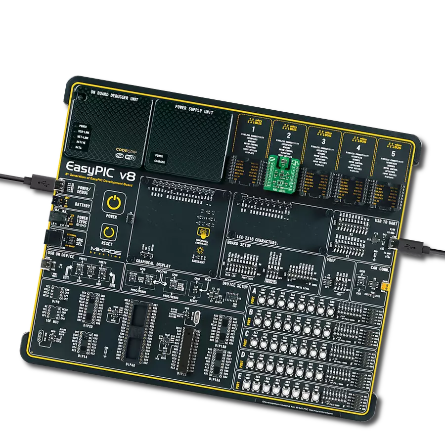
Clicker 4 for STM32F3 is a compact development board designed as a complete solution, you can use it to quickly build your own gadgets with unique functionalities. Featuring a STM32F302VCT6, four mikroBUS™ sockets for Click boards™ connectivity, power managment, and more, it represents a perfect solution for the rapid development of many different types of applications. At its core, there is a STM32F302VCT6 MCU, a powerful microcontroller by STMicroelectronics, based on the high-
performance Arm® Cortex®-M4 32-bit processor core operating at up to 168 MHz frequency. It provides sufficient processing power for the most demanding tasks, allowing Clicker 4 to adapt to any specific application requirements. Besides two 1x20 pin headers, four improved mikroBUS™ sockets represent the most distinctive connectivity feature, allowing access to a huge base of Click boards™, growing on a daily basis. Each section of Clicker 4 is clearly marked, offering an intuitive and clean interface. This makes working with the development
board much simpler and thus, faster. The usability of Clicker 4 doesn’t end with its ability to accelerate the prototyping and application development stages: it is designed as a complete solution which can be implemented directly into any project, with no additional hardware modifications required. Four mounting holes [4.2mm/0.165”] at all four corners allow simple installation by using mounting screws. For most applications, a nice stylish casing is all that is needed to turn the Clicker 4 development board into a fully functional, custom design.

Microcontroller Overview
MCU Card / MCU

Architecture
ARM Cortex-M4
MCU Memory (KB)
256
Silicon Vendor
STMicroelectronics
Pin count
100
RAM (Bytes)
40960
You complete me!
Accessories
This probe can be used with all pH meters with an input for the BNC connection with a 1m cable. The sensitive part of the probe (in the shape of a ball) is partially protected by a probe's plastic body, which reduces the possibility of mechanical damage. The EPH101 is used to measure the pH value of various liquids (due to the present plastic protection), and it can also be immersed in liquids inflowed in a system). It is stored in a plastic gel bottle with a very long shelf life. A pH (potential of Hydrogen) probe measures the hydrogen ion activity in a liquid. A membrane at the tip of a pH probe permits hydrogen ions from the liquid to be measured to defuse into the outer layer of the membrane while larger ions remain in the solution. The difference in the concentration of hydrogen ions outside the probe vs. inside the pH probe creates a small current proportional to the concentration of hydrogen ions in the measured liquid.

Used MCU Pins
mikroBUS™ mapper
Take a closer look
Click board™ Schematic

Step by step
Project assembly

Start by selecting your development board and Click board™. Begin with the CLICKER 4 for STM32F302VCT6 as your development board.


Track your results in real time
Application Output
1. Application Output - In Debug mode, the 'Application Output' window enables real-time data monitoring, offering direct insight into execution results. Ensure proper data display by configuring the environment correctly using the provided tutorial.

2. UART Terminal - Use the UART Terminal to monitor data transmission via a USB to UART converter, allowing direct communication between the Click board™ and your development system. Configure the baud rate and other serial settings according to your project's requirements to ensure proper functionality. For step-by-step setup instructions, refer to the provided tutorial.

3. Plot Output - The Plot feature offers a powerful way to visualize real-time sensor data, enabling trend analysis, debugging, and comparison of multiple data points. To set it up correctly, follow the provided tutorial, which includes a step-by-step example of using the Plot feature to display Click board™ readings. To use the Plot feature in your code, use the function: plot(*insert_graph_name*, variable_name);. This is a general format, and it is up to the user to replace 'insert_graph_name' with the actual graph name and 'variable_name' with the parameter to be displayed.

Software Support
Library Description
This library contains API for pH 2 Click driver.
Key functions:
ph2_calibrate- Ph 2 calibrate functionph2_calculate_ph- Ph 2 calculate pH value functionph2_calibrate_offset- Ph 2 calibrate offset function
Open Source
Code example
The complete application code and a ready-to-use project are available through the NECTO Studio Package Manager for direct installation in the NECTO Studio. The application code can also be found on the MIKROE GitHub account.
/*!
 * @file main.c
 * @brief pH 2 Click Example.
 *
 * # Description
 * This library contains API for pH 2 Click driver.
 * The library initializes and defines the I2C bus drivers or
 * ADC drivers to read data from pH probe.
 *
 * The demo application is composed of two sections :
 *
 * ## Application Init
 * Initializes the driver and performs offset calibration,
 * as well as calibration in pH-neutral substance.

 *
 * ## Application Task
 * This example demonstrates the use of the pH 2 Click board by
 * reading pH value of the substance where probe is placed.
 *
 * @author Stefan Ilic
 *
 */

#include "board.h"
#include "log.h"
#include "ph2.h"

static ph2_t ph2;   /**< pH 2 Click driver object. */
static log_t logger;    /**< Logger object. */

void application_init ( void )
{
    log_cfg_t log_cfg;  /**< Logger config object. */
    ph2_cfg_t ph2_cfg;  /**< Click config object. */

    /**
     * Logger initialization.
     * Default baud rate: 115200
     * Default log level: LOG_LEVEL_DEBUG
     * @note If USB_UART_RX and USB_UART_TX
     * are defined as HAL_PIN_NC, you will
     * need to define them manually for log to work.
     * See @b LOG_MAP_USB_UART macro definition for detailed explanation.
     */
    LOG_MAP_USB_UART( log_cfg );
    log_init( &logger, &log_cfg );
    log_info( &logger, " Application Init " );

    // Click initialization.
    ph2_cfg_setup( &ph2_cfg );
    PH2_MAP_MIKROBUS( ph2_cfg, MIKROBUS_1 );
    err_t init_flag = ph2_init( &ph2, &ph2_cfg );
    if ( ( ADC_ERROR == init_flag ) || ( I2C_MASTER_ERROR == init_flag ) )
    {
        log_error( &logger, " Communication init." );
        for ( ; ; );
    }

    log_printf( &logger, " ================================ \r\n" );
    log_printf( &logger, "     Performing calibration       \r\n" );
    log_printf( &logger, " ================================ \r\n" );
    log_printf( &logger, " Disconect BNC connector, \r\n" );
    log_printf( &logger, "    short-circuit it, \r\n" );
    log_printf( &logger, " adjust offset potentiometer \r\n" );
    log_printf( &logger, " ================================ \r\n" );
    log_printf( &logger, " STAT1 - turn clockwise \r\n" );
    log_printf( &logger, " STAT2 - turn counter-clockwise \r\n" );
    log_printf( &logger, " ================================ \r\n" );

    ph2_calibrate_offset( &ph2 );

    log_printf( &logger, " Calibration completed \r\n" );
    log_printf( &logger, " ================================ \r\n" );

    log_printf( &logger, " Connect probe back \r\n" );
    log_printf( &logger, " ================================ \r\n" );
    Delay_ms ( 1000 );
    Delay_ms ( 1000 );
    Delay_ms ( 1000 );
    Delay_ms ( 1000 );
    Delay_ms ( 1000 );
    log_printf( &logger, "  Place probe into pH  \r\n" );
    log_printf( &logger, " neutral substance for \r\n" );
    log_printf( &logger, " mid point calibration \r\n" );
    log_printf( &logger, " ================================ \r\n" );
    Delay_ms ( 1000 );
    Delay_ms ( 1000 );
    Delay_ms ( 1000 );
    Delay_ms ( 1000 );
    Delay_ms ( 1000 );
    log_printf( &logger, " Starting calibration  \r\n" );
    log_printf( &logger, " ================================ \r\n" );

    ph2_calibrate( &ph2, 7 );

    log_printf( &logger, " Calibration done!  \r\n" );
    log_printf( &logger, " ================================ \r\n" );

    log_info( &logger, " Application Task " );
    log_printf( &logger, " ================================ \r\n" );
}

void application_task ( void )
{
    float pH_val = 0;
    ph2_calculate_ph( &ph2, &pH_val );
    log_printf( &logger, " pH value: %.3f \r\n", pH_val );
    log_printf( &logger, " ================================ \r\n" );
    Delay_ms ( 1000 );
}

int main ( void )
{
    /* Do not remove this line or clock might not be set correctly. */
    #ifdef PREINIT_SUPPORTED
    preinit();
    #endif

    application_init( );

    for ( ; ; )
    {
        application_task( );
    }

    return 0;
}

// ------------------------------------------------------------------------ END
Additional Support
Resources
Category:Environmental