Accurately monitor and control indoor climate conditions using BME280 and ATmega328P
Tri-Meteo Nexus

Published Feb 14, 2024
Click board™
Weather Click
Dev. board
Arduino UNO Rev3
Compiler
NECTO Studio
MCU
ATmega328P
Enhance weather forecasting and environmental research with our integrated sensor solution, providing valuable data for meteorologists and scientists to analyze climate patterns and trends
A
A
Hardware Overview
How does it work?
Weather Click is based on the BME280, a combined humidity and pressure sensor from Bosch Sensortec. The BME280 itself contains sensors from each of the environmental measurements. The humidity sensor has high overall accuracy and an extremely fast response time. The pressure sensor has extremely high accuracy and resolution as an absolute barometric sensor. The temperature sensor is basically used for temperature compensation, thus for accurate readings. Nevertheless, it has low noise and high resolution and can be used for ambient temperature readings. The Weather Click can work in one of three power modes. Sleep mode is the first mode the sensor enters after the Power-On reset, when no measurements are performed with
its power consumption at the minimum. In Forced mode, the sensor performs a single measurement and returns to Sleep mode. For the next measurement, the Forced mode must be selected again. The Normal mode means the sensor will take measurements in automated perpetual cycling between measurement and inactive periods. The sensors inside the BME280 have different output resolutions, with 16-bit ADC for humidity and up to 20-bit for pressure readings. An internal IIR filter helps suppress the disturbance of many shorter changes, such as a wind blowing into the sensor, slamming a door, and such. To achieve a high resolution and low noise of readings, the IIR filter must be enabled. Weather Click can use a standard 2-Wire I2C
interface supporting standard, fast, and high speeds or an SPI serial interface to communicate with the host MCU. The communication interface can be selected via SPI I2C 4-jumper sets, with the I2C interface selected by default. All four jumpers must be in place for the Weather Click to work properly. The I2C address can be selected via the ADDR jumper, with 0 set by default. This Click board™ can be operated only with a 3.3V logic voltage level. The board must perform appropriate logic voltage level conversion before using MCUs with different logic levels. Also, it comes equipped with a library containing functions and an example code that can be used as a reference for further development.

Features overview
Development board
Arduino UNO is a versatile microcontroller board built around the ATmega328P chip. It offers extensive connectivity options for various projects, featuring 14 digital input/output pins, six of which are PWM-capable, along with six analog inputs. Its core components include a 16MHz ceramic resonator, a USB connection, a power jack, an
ICSP header, and a reset button, providing everything necessary to power and program the board. The Uno is ready to go, whether connected to a computer via USB or powered by an AC-to-DC adapter or battery. As the first USB Arduino board, it serves as the benchmark for the Arduino platform, with "Uno" symbolizing its status as the
first in a series. This name choice, meaning "one" in Italian, commemorates the launch of Arduino Software (IDE) 1.0. Initially introduced alongside version 1.0 of the Arduino Software (IDE), the Uno has since become the foundational model for subsequent Arduino releases, embodying the platform's evolution.

Microcontroller Overview
MCU Card / MCU

Architecture
AVR
MCU Memory (KB)
32
Silicon Vendor
Microchip
Pin count
28
RAM (Bytes)
2048
You complete me!
Accessories
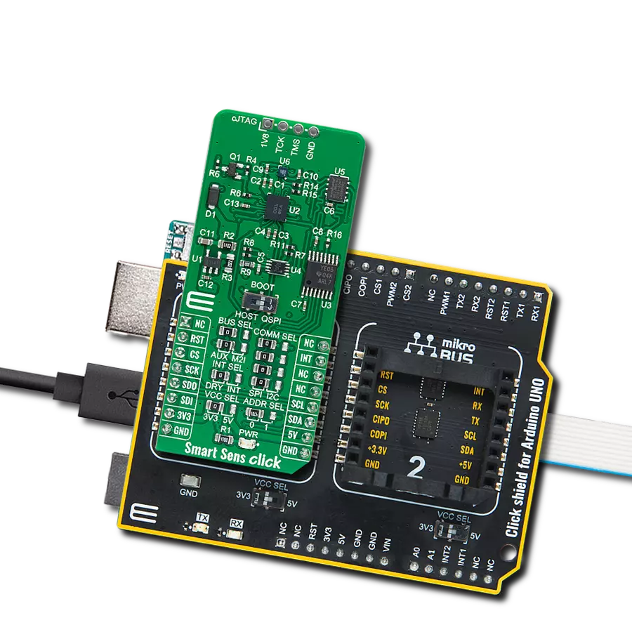
Click Shield for Arduino UNO has two proprietary mikroBUS™ sockets, allowing all the Click board™ devices to be interfaced with the Arduino UNO board without effort. The Arduino Uno, a microcontroller board based on the ATmega328P, provides an affordable and flexible way for users to try out new concepts and build prototypes with the ATmega328P microcontroller from various combinations of performance, power consumption, and features. The Arduino Uno has 14 digital input/output pins (of which six can be used as PWM outputs), six analog inputs, a 16 MHz ceramic resonator (CSTCE16M0V53-R0), a USB connection, a power jack, an ICSP header, and reset button. Most of the ATmega328P microcontroller pins are brought to the IO pins on the left and right edge of the board, which are then connected to two existing mikroBUS™ sockets. This Click Shield also has several switches that perform functions such as selecting the logic levels of analog signals on mikroBUS™ sockets and selecting logic voltage levels of the mikroBUS™ sockets themselves. Besides, the user is offered the possibility of using any Click board™ with the help of existing bidirectional level-shifting voltage translators, regardless of whether the Click board™ operates at a 3.3V or 5V logic voltage level. Once you connect the Arduino UNO board with our Click Shield for Arduino UNO, you can access hundreds of Click boards™, working with 3.3V or 5V logic voltage levels.

Used MCU Pins
mikroBUS™ mapper
Take a closer look
Click board™ Schematic

Step by step
Project assembly

Start by selecting your development board and Click board™. Begin with the Arduino UNO Rev3 as your development board.


Track your results in real time
Application Output
1. Application Output - In Debug mode, the 'Application Output' window enables real-time data monitoring, offering direct insight into execution results. Ensure proper data display by configuring the environment correctly using the provided tutorial.

2. UART Terminal - Use the UART Terminal to monitor data transmission via a USB to UART converter, allowing direct communication between the Click board™ and your development system. Configure the baud rate and other serial settings according to your project's requirements to ensure proper functionality. For step-by-step setup instructions, refer to the provided tutorial.

3. Plot Output - The Plot feature offers a powerful way to visualize real-time sensor data, enabling trend analysis, debugging, and comparison of multiple data points. To set it up correctly, follow the provided tutorial, which includes a step-by-step example of using the Plot feature to display Click board™ readings. To use the Plot feature in your code, use the function: plot(*insert_graph_name*, variable_name);. This is a general format, and it is up to the user to replace 'insert_graph_name' with the actual graph name and 'variable_name' with the parameter to be displayed.

Software Support
Library Description
This library contains API for Weather Click driver.
Key functions:
weather_get_ambient_data- Use this function to read the temperature, pressure and humidity dataweather_get_device_id- You can use this function as a check on click communication with your MCUweather_measurement_cfg- Use this function to set up new settings
Open Source
Code example
The complete application code and a ready-to-use project are available through the NECTO Studio Package Manager for direct installation in the NECTO Studio. The application code can also be found on the MIKROE GitHub account.
/*!
 * @file
 * @brief Weather Click example
 *
 * # Description
 * This demo-app shows the temperature, pressure and humidity measurement using Weather Click.
 *
 * The demo application is composed of two sections :
 *
 * ## Application Init
 * Configuring Clicks and log objects.
 * Setting the Click in the default configuration to start the measurement.
 *
 * ## Application Task
 * Reads Temperature data, Relative Humidity data and Pressure data,
 * and displays them on USB UART every 1500ms.
 *
 * @author MikroE Team
 *
 */

#include "board.h"
#include "log.h"
#include "weather.h"

static weather_t weather;
static log_t logger;

void application_init ( void )
{
    log_cfg_t log_cfg;
    weather_cfg_t weather_cfg;

    /**
     * Logger initialization.
     * Default baud rate: 115200
     * Default log level: LOG_LEVEL_DEBUG
     * @note If USB_UART_RX and USB_UART_TX
     * are defined as HAL_PIN_NC, you will
     * need to define them manually for log to work.
     * See @b LOG_MAP_USB_UART macro definition for detailed explanation.
     */
    LOG_MAP_USB_UART( log_cfg );
    log_init( &logger, &log_cfg );
    log_info( &logger, " Application Init " );

    // Click initialization.
    weather_cfg_setup( &weather_cfg );
    WEATHER_MAP_MIKROBUS( weather_cfg, MIKROBUS_1 );
    if ( WEATHER_OK != weather_init( &weather, &weather_cfg ) )
    {
        log_error( &logger, " Communication init." );
        for ( ; ; );
    }

    if ( WEATHER_OK != weather_default_cfg ( &weather ) )
    {
        log_error( &logger, " Default configuration." );
        for ( ; ; );
    }

    log_info( &logger, " Application Task " );
}

void application_task ( void )
{
    weather_data_t weather_data;

    if ( WEATHER_OK == weather_get_ambient_data( &weather, &weather_data ) )
    {
        log_printf( &logger, " \r\n ---- Weather data ----- \r\n" );
        log_printf( &logger, "[PRESSURE]: %.2f mBar.\n\r", weather_data.pressure );
        log_printf( &logger, "[TEMPERATURE]: %.2f C.\n\r", weather_data.temperature );
        log_printf( &logger, "[HUMIDITY]: %.2f %%.\n\r", weather_data.humidity );

        Delay_ms ( 1000 );
        Delay_ms ( 500 );
    }
}

int main ( void )
{
    /* Do not remove this line or clock might not be set correctly. */
    #ifdef PREINIT_SUPPORTED
    preinit();
    #endif

    application_init( );

    for ( ; ; )
    {
        application_task( );
    }

    return 0;
}


// ------------------------------------------------------------------------ END
Additional Support
Resources
Category:Environmental