Experience a new level of environmental insight with BME680 and STM32L496AG
MultiSense EnviroGuard
Published Jul 22, 2025
Click board™
Environment Click
Dev. board
Discovery kit with STM32L496AG MCU
Compiler
NECTO Studio
MCU
STM32L496AG
Harness the power of our all-in-one solution to gain a holistic view of your surroundings, measuring temperature, humidity, pressure, and VOC gases to make informed decisions for a healthier environment
A
A
Hardware Overview
How does it work?
Environment Click is based on the BME680, a digital environmental sensor that combines gas, humidity, temperature, and barometric pressure sensing from Bosch Sensortec. The gas sensor within the BME680 can detect a broad range of gases to measure indoor air quality for personal well-being. Gases that the BME680 detects include Volatile Organic Compounds (VOC) from paints (such as formaldehyde), lacquers, paint strippers, cleaning supplies, office equipment, glues, adhesives, and alcohol. It offers reduced power consumption, improved accuracy specifications, and a configurable host interface for the fastest data transfer. It covers extended operating pressure, humidity, and temperature ranges from 300-1100hPa, 0-100%RH and from
-40°C to +85°C with the accuracy of ±3%RH and ±0.5°C. The integrated temperature sensor has been optimized for the lowest noise and highest resolution. Its output is used for temperature compensation of the pressure and humidity sensors and can also be used to estimate the ambient temperature. In addition, the BME680 also has an integrated humidity and absolute barometric pressure sensor with extremely high accuracy and resolution over a wide temperature range, providing a swift response time for fast context awareness applications.
Environment Click allows using both I2C and SPI interfaces with a maximum frequency of 3.4MHz for I2C and 10MHz for SPI communication. The selection can be made by positioning SMD
jumpers labeled as COMM SEL in an appropriate position. Note that all the jumpers' positions must be on the same side, or the Click board™ may become unresponsive. While the I2C interface is selected, the BME680 allows choosing the least significant bit (LSB) of its I2C slave address using the SMD jumper labeled ADDR SEL. This Click board™ can be operated only with a 3.3V logic voltage level. The board must perform appropriate logic voltage level conversion before using MCUs with different logic levels. Also, it comes equipped with a library containing functions and an example code that can be used, as a reference, for further development.


Features overview
Development board
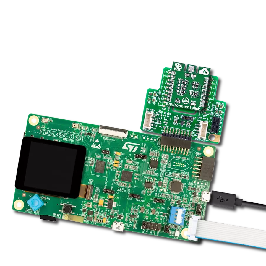
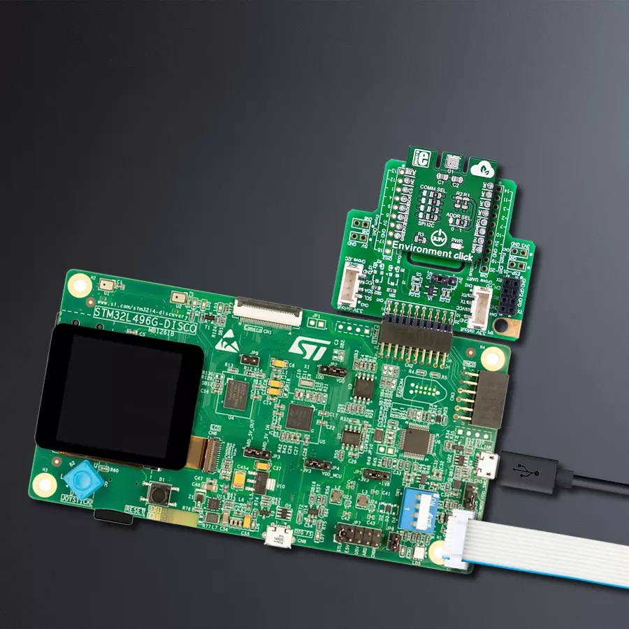
The 32L496GDISCOVERY Discovery kit serves as a comprehensive demonstration and development platform for the STM32L496AG microcontroller, featuring an Arm® Cortex®-M4 core. Designed for applications that demand a balance of high performance, advanced graphics, and ultra-low power consumption, this kit enables seamless prototyping for a wide range of embedded solutions. With its innovative energy-efficient
architecture, the STM32L496AG integrates extended RAM and the Chrom-ART Accelerator, enhancing graphics performance while maintaining low power consumption. This makes the kit particularly well-suited for applications involving audio processing, graphical user interfaces, and real-time data acquisition, where energy efficiency is a key requirement. For ease of development, the board includes an onboard ST-LINK/V2-1
debugger/programmer, providing a seamless out-of-the-box experience for loading, debugging, and testing applications without requiring additional hardware. The combination of low power features, enhanced memory capabilities, and built-in debugging tools makes the 32L496GDISCOVERY kit an ideal choice for prototyping advanced embedded systems with state-of-the-art energy efficiency.

Microcontroller Overview
MCU Card / MCU

Architecture
ARM Cortex-M4
MCU Memory (KB)
1024
Silicon Vendor
STMicroelectronics
Pin count
169
RAM (Bytes)
327680
Used MCU Pins
mikroBUS™ mapper
Take a closer look
Click board™ Schematic

Step by step
Project assembly

Start by selecting your development board and Click board™. Begin with the Discovery kit with STM32L496AG MCU as your development board.


Track your results in real time
Application Output
1. Application Output - In Debug mode, the 'Application Output' window enables real-time data monitoring, offering direct insight into execution results. Ensure proper data display by configuring the environment correctly using the provided tutorial.

2. UART Terminal - Use the UART Terminal to monitor data transmission via a USB to UART converter, allowing direct communication between the Click board™ and your development system. Configure the baud rate and other serial settings according to your project's requirements to ensure proper functionality. For step-by-step setup instructions, refer to the provided tutorial.

3. Plot Output - The Plot feature offers a powerful way to visualize real-time sensor data, enabling trend analysis, debugging, and comparison of multiple data points. To set it up correctly, follow the provided tutorial, which includes a step-by-step example of using the Plot feature to display Click board™ readings. To use the Plot feature in your code, use the function: plot(*insert_graph_name*, variable_name);. This is a general format, and it is up to the user to replace 'insert_graph_name' with the actual graph name and 'variable_name' with the parameter to be displayed.

Software Support
Library Description
This library contains API for Environment Click driver.
Key functions:
environment_get_gas_resistance- This function gets gas resistance value from BME680 chipenvironment_get_pressure- This function gets pressure value of BME680 chipenvironment_get_humidity- This function get humidity value of BME680 chip
Open Source
Code example
The complete application code and a ready-to-use project are available through the NECTO Studio Package Manager for direct installation in the NECTO Studio. The application code can also be found on the MIKROE GitHub account.
/*!
 * \file
 * \brief Environment Click example
 *
 * # Description
 * Example demonstrates use of the Environment Click board.
 *
 * The demo application is composed of two sections :
 *
 * ## Application Init
 * Initialization driver enables - Device software reset, check device ID, set default configuration of BME680 chip, also display logs.
 *
 * ## Application Task
 * This is an example which demonstrates the use of Environment Click board.
 * Measures temperature, humidity, pressure and gas resistance data from the BME680 chip sensor.
 * Displays ambient temperature data [ degrees Celsius ],
 * humidity data [ % ], pressure data [ mbar ] and gas resistance.
 * Results are being sent to the Usart Terminal where you can track their changes.
 * All data logs write on usb uart changes for every 2 sec.
 *
 *
 * \author MikroE Team
 *
 */
// ------------------------------------------------------------------- INCLUDES

#include "board.h"
#include "log.h"
#include "environment.h"

// ------------------------------------------------------------------ VARIABLES

static environment_t environment;
static log_t logger;
static float temperature;
static float pressure;
static float humidity;
static int32_t gas;

// ------------------------------------------------------ APPLICATION FUNCTIONS

void application_init ( void )
{
    log_cfg_t log_cfg;
    environment_cfg_t cfg;

    /**
     * Logger initialization.
     * Default baud rate: 115200
     * Default log level: LOG_LEVEL_DEBUG
     * @note If USB_UART_RX and USB_UART_TX
     * are defined as HAL_PIN_NC, you will
     * need to define them manually for log to work.
     * See @b LOG_MAP_USB_UART macro definition for detailed explanation.
     */
    LOG_MAP_USB_UART( log_cfg );
    log_init( &logger, &log_cfg );
    log_info( &logger, "---- Application Init ----" );

    //  Click initialization.

    environment_cfg_setup( &cfg );
    ENVIRONMENT_MAP_MIKROBUS( cfg, MIKROBUS_1 );
    environment_init( &environment , &cfg );
    environment_default_cfg( &environment );
}

void application_task ( void )
{
    //  Task implementation.

    temperature = environment_get_temperature( &environment);
    log_printf( &logger, " Temperature : %.2fC", temperature);

    humidity = environment_get_humidity( &environment );
    log_printf( &logger, "      Humidity : %f%%", humidity);

    pressure = environment_get_pressure( &environment );
    log_printf( &logger, "      Pressure : %.3fmbar", pressure);

    gas = environment_get_gas_resistance( &environment );
    log_printf( &logger, "      Gas Resistance : %ld\r\n", gas);

    Delay_ms ( 1000 );
    Delay_ms ( 1000 );
}

int main ( void )
{
    /* Do not remove this line or clock might not be set correctly. */
    #ifdef PREINIT_SUPPORTED
    preinit();
    #endif

    application_init( );

    for ( ; ; )
    {
        application_task( );
    }

    return 0;
}

// ------------------------------------------------------------------------ END
Additional Support
Resources
Category:Environmental