Combine GPS/GLONASS accuracy with GSM mobile communication using SIM868 and PIC32MX675F512L
Stay on course, stay connected

Published Sep 09, 2023
Click board™
GSM/GNSS 2 Click
Dev. board
UNI-DS v8
Compiler
NECTO Studio
MCU
PIC32MX675F512L
Efficiency, accuracy, and connectivity define our solution's purpose. It's engineered to enhance mobile operations by offering integrated GPS/GLONASS and GSM functionality, streamlining tracking and mobile communication needs
A
A
Hardware Overview
How does it work?
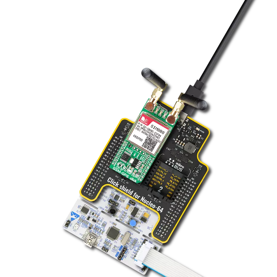
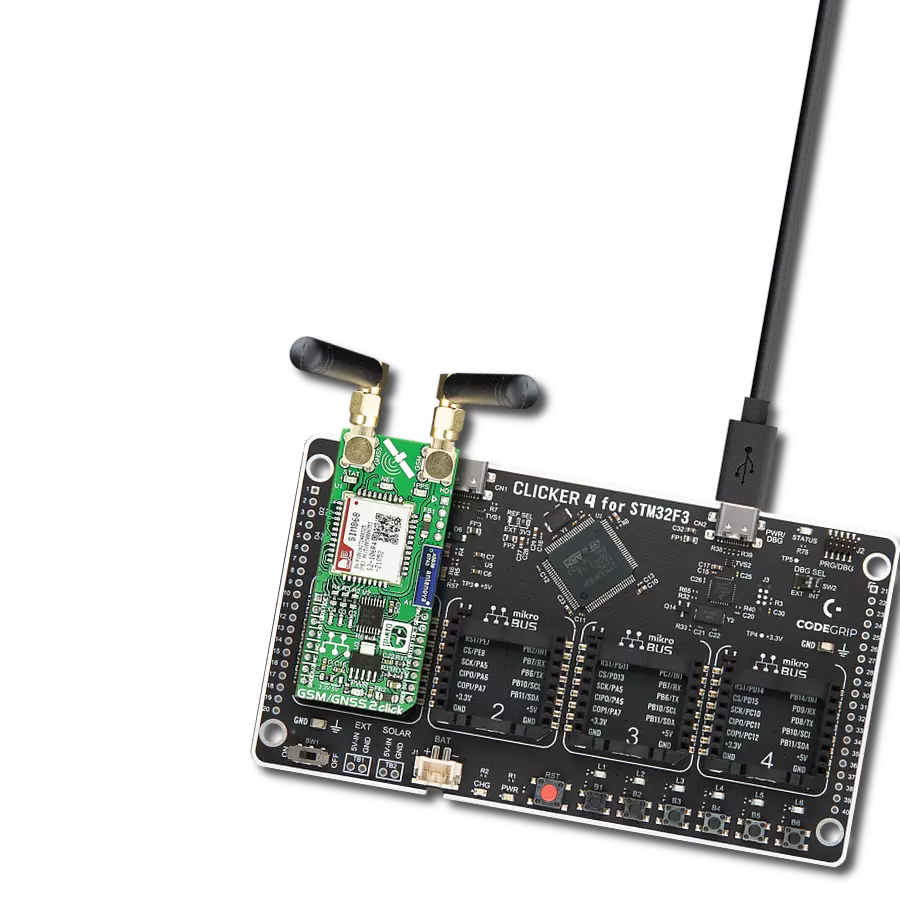
GSM/GNSS 2 Click is based on the SIM868, a multi-purpose module that integrates a high-performance GNSS engine and a GSM/GPRS engine from SIMCom. The quad-band GSM/GPRS engine can work at 850, 900, 1800, and 1900MHz. It also features GPRS multi-slot class 12 and supports the GPRS coding schemes CS-1, CS-2, CS-3, and CS-4. The GNSS solution offers best-in-class acquisition and tracking sensitivity, Time-To-First-Fix (TTFF), and accuracy. The GSM part of the SIM868 is integrated with Internet service protocols such as TCP, UDP, PPP, HTTP, and FTP. The excellent positioning performance, low power consumption, and dual μSIM card interfaces make SIM868 the superb choice for many M2M applications. The SIM868 module has to be powered by a clean and stable power supply. The voltage for the module to work correctly is 4V, derived from the 5V mikroBUS™ power rail through the MCP1826, a 1A low drop output (LDO) regulator. The main 4V power supply is also the
power supply for the GSM/GNSS block of the SIM868. Also, activation of the module itself is possible via the RST pin on the mikroBUS™ socket connected to the PWRKEY pin used for turning the module ON and OFF. The SIM868 communicates with MCU using the UART interface with commonly used UART RX and TX pins with the hardware flow control pins UART CTS, RTS, RI (Clear to Send, Ready to Send, and Ring Indicator). The GSM/GNSS 2 Click also has an onboard MicroSD/MicroSIM card socket with a card detection feature routed to the AN pin on the mikroBUS™ socket, A5839 Bluetooth 3.0 2.4GHz chip antenna, which the SIM868 module version supports, and an additional header labeled as HD1 for audio interface (channels for connecting speakers and a microphone). In addition to all these features, this Click board™ has three yellow LED indicators labeled NET, STAT, and 1PPS. The network status NET indicates if the module is attached or not to a network, Power-ON Status
STAT indicates the operating status of the module, and successfully positioning 1PPS shows one pulse per second synchronized to GNSS satellites. Furthermore, it possesses two SMA antenna connectors with an impedance of 50Ω, labeled as GNSS and GSM, used for connecting the appropriate antenna that MIKROE offers. It can receive GPS coordinates, time, and other information from orbiting satellites when connected to a GPS antenna. The Click board™ can be used for all GSM functions — calls, messages (SMS, MMS), and mobile internet. This Click board™ can operate with either 3.3V or 5V logic voltage levels selected via an onboard jumper. This way, both 3.3V and 5V capable MCUs can use the communication lines properly. Also, this Click board™ comes equipped with a library containing easy-to-use functions and an example code that can be used as a reference for further development.

Features overview
Development board
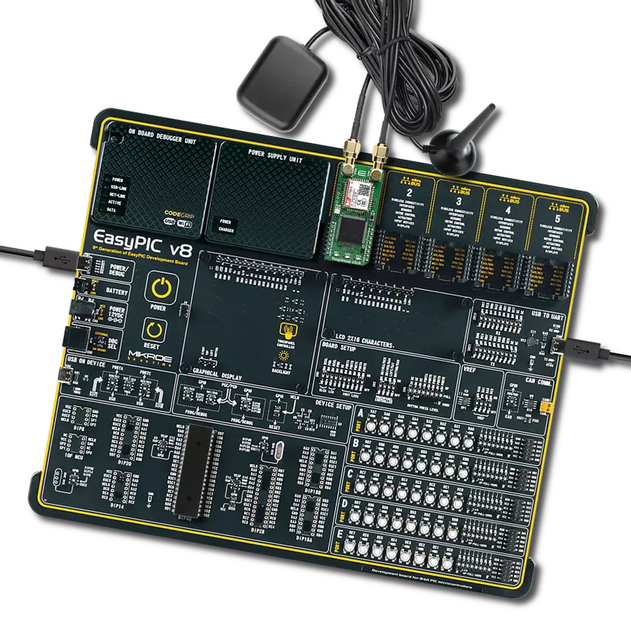
UNI-DS v8 is a development board specially designed for the needs of rapid development of embedded applications. It supports a wide range of microcontrollers, such as different STM32, Kinetis, TIVA, CEC, MSP, PIC, dsPIC, PIC32, and AVR MCUs regardless of their number of pins, and a broad set of unique functions, such as the first-ever embedded debugger/programmer over WiFi. The development board is well organized and designed so that the end-user has all the necessary elements, such as switches, buttons, indicators, connectors, and others, in one place. Thanks to innovative manufacturing technology, UNI-DS v8 provides a fluid and immersive working experience, allowing access anywhere and under any
circumstances at any time. Each part of the UNI-DS v8 development board contains the components necessary for the most efficient operation of the same board. An advanced integrated CODEGRIP programmer/debugger module offers many valuable programming/debugging options, including support for JTAG, SWD, and SWO Trace (Single Wire Output)), and seamless integration with the Mikroe software environment. Besides, it also includes a clean and regulated power supply module for the development board. It can use a wide range of external power sources, including a battery, an external 12V power supply, and a power source via the USB Type-C (USB-C) connector. Communication options such as USB-UART, USB
HOST/DEVICE, CAN (on the MCU card, if supported), and Ethernet is also included. In addition, it also has the well-established mikroBUS™ standard, a standardized socket for the MCU card (SiBRAIN standard), and two display options for the TFT board line of products and character-based LCD. UNI-DS v8 is an integral part of the Mikroe ecosystem for rapid development. Natively supported by Mikroe software tools, it covers many aspects of prototyping and development thanks to a considerable number of different Click boards™ (over a thousand boards), the number of which is growing every day.

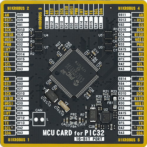
Microcontroller Overview
MCU Card / MCU
Type
8th Generation
Architecture
PIC32
MCU Memory (KB)
512
Silicon Vendor
Microchip
Pin count
100
RAM (Bytes)
65536
You complete me!
Accessories
Rubber Antenna GSM/GPRS Right Angle is the perfect companion for all GSM Click boards™ in our extensive lineup. This specialized antenna is designed to optimize your wireless connectivity with impressive features. With a wide frequency range spanning 824-894/1710-1990MHz or 890-960/1710-1890MHz, it can handle various frequency bands, ensuring a seamless and reliable connection. The antenna boasts an impedance of 50 Ohms and a gain of 2dB, enhancing signal reception and transmission. Its 70/180MHz bandwidth provides flexibility for diverse applications. The vertical polarization further enhances its performance. With a maximum input power capacity of 50W, this antenna ensures robust communication even under demanding conditions. Measuring a compact 50mm in length and featuring an SMA male connector, the Rubber Antenna GSM/GPRS Right Angle is a versatile and compact solution for your wireless communication needs.

Used MCU Pins
mikroBUS™ mapper
Take a closer look
Click board™ Schematic

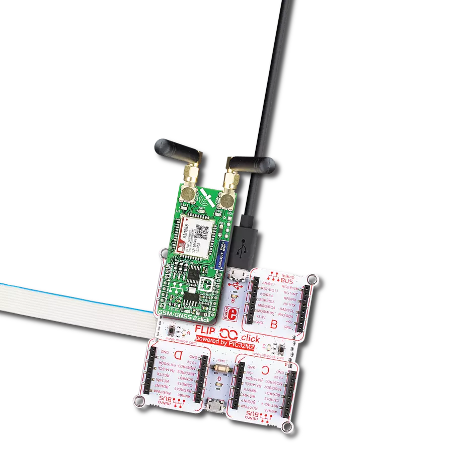
Step by step
Project assembly

Start by selecting your development board and Click board™. Begin with the UNI-DS v8 as your development board.


Software Support
Library Description
This library contains API for GSM/GNSS 2 Click driver.
Key functions:
gsmgnss2_send_cmd- Send command functiongsmgnss2_set_sim_apn- Set sim card APNgsmgnss2_send_sms_pdu- GSM GNSS send SMS in PDU mode.
Open Source
Code example
The complete application code and a ready-to-use project are available through the NECTO Studio Package Manager for direct installation in the NECTO Studio. The application code can also be found on the MIKROE GitHub account.
/*!
 * @file main.c
 * @brief GSM/GNSS 2 Click Example.
 *
 * # Description
 * This example reads and processes data from GSM/GNSS 2 Clicks.
 *
 * The demo application is composed of two sections :
 *
 * ## Application Init
 * Initializes the driver and powers up the module, then sets default configuration
 * for connecting the device to network.
 *
 * ## Application Task
 * Waits for the device to connect to network, then waits for the GNSS position fix. Once it get a fix,
 * it sends an SMS with GNSS info to the selected phone number approximately every 40 seconds.
 *
 * ## Additional Function
 * - static void gsmgnss2_clear_app_buf ( void )
 * - static void gsmgnss2_error_check( err_t error_flag )
 * - static void gsmgnss2_log_app_buf ( void )
 * - static void gsmgnss2_check_connection( void )
 * - static err_t gsmgnss2_rsp_check ( void )
 * - static err_t gsmgnss2_process ( void )
 * - static void gnss_parser_application ( void )
 *
 * @note
 * A passive GPS antenna is required for the GNSS to receive the position fix. It may take several minutes
 * for the module to receive the fix.
 * In order for the example to work, user needs to set the phone number to which he wants
 * to send an SMS, and also will need to set an APN and SMSC (required for PDU mode only) of entered SIM card.
 * Enter valid data for the following macros: SIM_APN, SIM_SMSC and PHONE_NUMBER_TO_MESSAGE.
 * Example.
    SIM_APN "vipmobile"
    SIM_SMSC "+381610401"
    PHONE_NUMBER_TO_MESSAGE "+381659999999"
 *
 * @author Mikroe Team
 *
 */
// ------------------------------------------------------------------- INCLUDES

#include "board.h"
#include "log.h"
#include "gsmgnss2.h"
#include "string.h"

#define APP_OK                              0
#define APP_ERROR_DRIVER                    -1
#define APP_ERROR_OVERFLOW                  -2
#define APP_ERROR_TIMEOUT                   -3

#define RSP_OK                              "OK"
#define RSP_ERROR                           "ERROR"

#define SIM_APN                             ""  // Set valid SIM APN
#define SIM_SMSC                            ""  // Set valid SMS Service Center Address - only in PDU mode
#define PHONE_NUMBER_TO_MESSAGE             ""  // Set Phone number to message

#define PROCESS_BUFFER_SIZE                 256

#define WAIT_FOR_CONNECTION                 0
#define CONNECTED_TO_NETWORK                1

static gsmgnss2_t gsmgnss2;
static log_t logger;

static char app_buf[ PROCESS_BUFFER_SIZE ] = { 0 };
static int32_t app_buf_len = 0;
static int32_t app_buf_cnt = 0;

static uint8_t app_connection_status        = WAIT_FOR_CONNECTION;

static err_t app_error_flag;
static uint8_t gnss_parser_flag = 0;
static uint8_t gnss_info_message[ 200 ] = { 0 };

/**
 * @brief GSM/GNSS 2 clearing application buffer.
 * @details This function clears memory of application buffer and reset its length and counter.
 * @note None.
 */
static void gsmgnss2_clear_app_buf ( void );

/**
 * @brief GSM/GNSS 2 data reading function.
 * @details This function reads data from device and concatenates data to application buffer.
 * @return @li @c  0 - Read some data.
 *         @li @c -1 - Nothing is read.
 *         @li @c -2 - Application buffer overflow.
 * See #err_t definition for detailed explanation.
 * @note None.
 */
static err_t gsmgnss2_process ( void );

/**
 * @brief GSM/GNSS 2 check for errors.
 * @details This function checks for different types of errors and logs them on UART.
 * @note None.
 */
static void gsmgnss2_error_check( err_t error_flag );

/**
 * @brief GSM/GNSS 2 logs application buffer.
 * @details This function logs data from application buffer.
 * @note None.
 */
static void gsmgnss2_log_app_buf ( void );

/**
 * @brief GSM/GNSS 2 response check.
 * @details This function checks for response and returns the status of response.
 * @return application status.
 * See #err_t definition for detailed explanation.
 * @note None.
 */
static err_t gsmgnss2_rsp_check ( void );

/**
 * @brief GSM/GNSS 2 check connection.
 * @details This function checks connection to the network and logs that status to UART.
 * @note None.
 */
static void gsmgnss2_check_connection( void );

/**
 * @brief GNSS parser application.
 * @details This function logs GNSS data on the USB UART and stores data in gnss_info_message buffer.
 * @param rsp Response buffer.
 * @note None.
 */
static void gnss_parser_application ( char *rsp );

// ------------------------------------------------------ APPLICATION FUNCTIONS

void application_init ( void )
{
    log_cfg_t log_cfg;  /**< Logger config object. */
    gsmgnss2_cfg_t gsmgnss2_cfg;  /**< Click config object. */

    /**
     * Logger initialization.
     * Default baud rate: 115200
     * Default log level: LOG_LEVEL_DEBUG
     * @note If USB_UART_RX and USB_UART_TX
     * are defined as HAL_PIN_NC, you will
     * need to define them manually for log to work.
     * See @b LOG_MAP_USB_UART macro definition for detailed explanation.
     */
    LOG_MAP_USB_UART( log_cfg );
    log_init( &logger, &log_cfg );
    log_info( &logger, " Application Init " );

    // Click initialization.
    gsmgnss2_cfg_setup( &gsmgnss2_cfg );
    GSMGNSS2_MAP_MIKROBUS( gsmgnss2_cfg, MIKROBUS_1 );
    gsmgnss2_init( &gsmgnss2, &gsmgnss2_cfg );

    gsmgnss2_module_power( &gsmgnss2, GSMGNSS2_MODULE_POWER_ON );

    // dummy read
    gsmgnss2_process( );
    gsmgnss2_clear_app_buf( );

    // AT
    gsmgnss2_send_cmd( &gsmgnss2, GSMGNSS2_CMD_AT );
    app_error_flag = gsmgnss2_rsp_check( );
    gsmgnss2_error_check( app_error_flag );
    Delay_ms ( 500 );

    // ATI - product information
    gsmgnss2_send_cmd( &gsmgnss2, GSMGNSS2_CMD_ATI );
    app_error_flag = gsmgnss2_rsp_check(  );
    gsmgnss2_error_check( app_error_flag );
    Delay_ms ( 500 );

    // CGMR - firmware version
    gsmgnss2_send_cmd( &gsmgnss2, GSMGNSS2_CMD_CGMR );
    app_error_flag = gsmgnss2_rsp_check(  );
    gsmgnss2_error_check( app_error_flag );
    Delay_ms ( 500 );

    // CMEE - Report Mobile Equipment Error
    gsmgnss2_send_cmd_with_parameter( &gsmgnss2, GSMGNSS2_CMD_CMEE, "2" );
    app_error_flag = gsmgnss2_rsp_check(  );
    gsmgnss2_error_check( app_error_flag );
    Delay_ms ( 500 );

    // COPS - deregister from network
    gsmgnss2_send_cmd_with_parameter( &gsmgnss2, GSMGNSS2_CMD_COPS, "2" );
    app_error_flag = gsmgnss2_rsp_check(  );
    gsmgnss2_error_check( app_error_flag );
    Delay_ms ( 500 );

    // CGDCONT - set sim apn
    gsmgnss2_set_sim_apn( &gsmgnss2, SIM_APN );
    app_error_flag = gsmgnss2_rsp_check(  );
    gsmgnss2_error_check( app_error_flag );
    Delay_ms ( 500 );

    // CFUN - full funtionality
    gsmgnss2_send_cmd_with_parameter( &gsmgnss2, GSMGNSS2_CMD_CFUN, "1" );
    app_error_flag = gsmgnss2_rsp_check(  );
    gsmgnss2_error_check( app_error_flag );
    Delay_ms ( 500 );

    // COPS - automatic mode
    gsmgnss2_send_cmd_with_parameter( &gsmgnss2, GSMGNSS2_CMD_COPS, "0" );
    app_error_flag = gsmgnss2_rsp_check(  );
    gsmgnss2_error_check( app_error_flag );
    Delay_ms ( 1000 );
    Delay_ms ( 1000 );

    // CREG - network registration status
    gsmgnss2_send_cmd_with_parameter( &gsmgnss2, GSMGNSS2_CMD_CREG, "1" );
    app_error_flag = gsmgnss2_rsp_check(  );
    gsmgnss2_error_check( app_error_flag );
    Delay_ms ( 500 );

    // SMS message format - PDU mode
    gsmgnss2_send_cmd_with_parameter( &gsmgnss2, GSMGNSS2_CMD_CMGF, "0" );
    app_error_flag = gsmgnss2_rsp_check(  );
    gsmgnss2_error_check( app_error_flag );
    Delay_ms ( 500 );

    // QGNSSC - power ON GNSS
    gsmgnss2_send_cmd_with_parameter( &gsmgnss2, GSMGNSS2_CMD_CGNSPWR, "1" );
    app_error_flag = gsmgnss2_rsp_check(  );
    gsmgnss2_error_check( app_error_flag );
    Delay_ms ( 500 );

    app_buf_len = 0;
    app_buf_cnt = 0;
    app_connection_status = WAIT_FOR_CONNECTION;
    log_info( &logger, " Application Task " );
    Delay_ms ( 1000 );
    Delay_ms ( 1000 );
    Delay_ms ( 1000 );
    Delay_ms ( 1000 );
    Delay_ms ( 1000 );
}

void application_task ( void )
{
    if ( app_connection_status == WAIT_FOR_CONNECTION )
    {
        // CREG - network registration status
        gsmgnss2_send_cmd_check( &gsmgnss2, GSMGNSS2_CMD_CREG );
        app_error_flag = gsmgnss2_rsp_check(  );
        gsmgnss2_error_check( app_error_flag );
        Delay_ms ( 500 );

        // CSQ - signal quality
        gsmgnss2_send_cmd( &gsmgnss2, GSMGNSS2_CMD_CSQ );
        app_error_flag = gsmgnss2_rsp_check(  );
        gsmgnss2_error_check( app_error_flag );
        Delay_ms ( 1000 );
        Delay_ms ( 1000 );
        Delay_ms ( 1000 );
        Delay_ms ( 1000 );
        Delay_ms ( 1000 );
    }
    else
    {
        log_info( &logger, "CONNECTED TO NETWORK" );

        for ( ; ; )
        {
            // Get GNSS info
            gnss_parser_flag = 1;
            gsmgnss2_send_cmd_with_parameter( &gsmgnss2, GSMGNSS2_CMD_CGNSTST, "1" );

            for ( ; ; )
            {
                if ( GSMGNSS2_OK == gsmgnss2_process( ) )
                {
                    gnss_parser_application( app_buf );

                    if ( gnss_parser_flag == 2 )
                    {
                        gsmgnss2_send_cmd_with_parameter( &gsmgnss2, GSMGNSS2_CMD_CGNSTST, "0" );
                        app_error_flag = gsmgnss2_rsp_check(  );
                        gsmgnss2_error_check( app_error_flag );
                        log_printf( &logger, "> Sending message to phone number...\r\n" );
                        gsmgnss2_send_sms_pdu ( &gsmgnss2, SIM_SMSC, PHONE_NUMBER_TO_MESSAGE, gnss_info_message );
                        app_error_flag = gsmgnss2_rsp_check(  );
                        gsmgnss2_error_check( app_error_flag );
                        // 30 seconds delay
                        Delay_ms ( 1000 );
                        Delay_ms ( 1000 );
                        Delay_ms ( 1000 );
                        Delay_ms ( 1000 );
                        Delay_ms ( 1000 );
                        Delay_ms ( 1000 );
                        Delay_ms ( 1000 );
                        Delay_ms ( 1000 );
                        Delay_ms ( 1000 );
                        Delay_ms ( 1000 );
                        Delay_ms ( 1000 );
                        Delay_ms ( 1000 );
                        Delay_ms ( 1000 );
                        Delay_ms ( 1000 );
                        Delay_ms ( 1000 );
                        Delay_ms ( 1000 );
                        Delay_ms ( 1000 );
                        Delay_ms ( 1000 );
                        Delay_ms ( 1000 );
                        Delay_ms ( 1000 );
                        Delay_ms ( 1000 );
                        Delay_ms ( 1000 );
                        Delay_ms ( 1000 );
                        Delay_ms ( 1000 );
                        Delay_ms ( 1000 );
                        Delay_ms ( 1000 );
                        Delay_ms ( 1000 );
                        Delay_ms ( 1000 );
                        Delay_ms ( 1000 );
                        Delay_ms ( 1000 );
                    }
                    if ( gnss_parser_flag != 1 )
                    {
                        break;
                    }
                }
            }
        }
    }
}

int main ( void )
{
    /* Do not remove this line or clock might not be set correctly. */
    #ifdef PREINIT_SUPPORTED
    preinit();
    #endif

    application_init( );

    for ( ; ; )
    {
        application_task( );
    }

    return 0;
}

static void gsmgnss2_clear_app_buf ( void )
{
    memset( app_buf, 0, app_buf_len );
    app_buf_len = 0;
    app_buf_cnt = 0;
}

static err_t gsmgnss2_process ( void )
{
    int32_t rx_size;
    char rx_buff[ PROCESS_BUFFER_SIZE ] = { 0 };

    rx_size = gsmgnss2_generic_read( &gsmgnss2, rx_buff, PROCESS_BUFFER_SIZE );

    if ( rx_size > 0 )
    {
        int32_t buf_cnt = 0;

        if ( app_buf_len + rx_size > PROCESS_BUFFER_SIZE )
        {
            rx_size = PROCESS_BUFFER_SIZE - app_buf_len;
        }
        else
        {
            buf_cnt = app_buf_len;
            app_buf_len += rx_size;
        }

        for ( int32_t rx_cnt = 0; rx_cnt < rx_size; rx_cnt++ )
        {
            if ( rx_buff[ rx_cnt ] != 0 )
            {
                app_buf[ ( buf_cnt + rx_cnt ) ] = rx_buff[ rx_cnt ];
            }
            else
            {
                app_buf_len--;
                buf_cnt--;
            }
        }
        return GSMGNSS2_OK;
    }
    return GSMGNSS2_ERROR;
}

static err_t gsmgnss2_rsp_check ( void )
{
    uint32_t timeout_cnt = 0;
    uint32_t timeout = 100000;

    err_t error_flag = gsmgnss2_process(  );

    if ( ( error_flag != 0 ) && ( error_flag != -1 ) )
    {
        return error_flag;
    }

    while ( ( strstr( app_buf, RSP_OK ) == 0 ) && ( strstr( app_buf, RSP_ERROR ) == 0 ) )
    {
        error_flag = gsmgnss2_process(  );
        if ( ( error_flag != 0 ) && ( error_flag != -1 ) )
        {
            return error_flag;
        }

        timeout_cnt++;
        if ( timeout_cnt > timeout )
        {
            while ( ( strstr( app_buf, RSP_OK ) == 0 ) && ( strstr( app_buf, RSP_ERROR ) == 0 ) )
            {
                gsmgnss2_send_cmd( &gsmgnss2, GSMGNSS2_CMD_AT );
                gsmgnss2_process(  );
                Delay_ms ( 100 );
            }
            gsmgnss2_clear_app_buf(  );
            return APP_ERROR_TIMEOUT;
        }

        Delay_ms ( 1 );
    }

    gsmgnss2_check_connection();

    gsmgnss2_log_app_buf();

    return APP_OK;
}

static void gsmgnss2_error_check( err_t error_flag )
{
    if ( ( error_flag != 0 ) && ( error_flag != -1 ) )
    {
        switch ( error_flag )
        {
            case -2:
                log_error( &logger, " Overflow!" );
                break;
            case -3:
                log_error( &logger, " Timeout!" );
                break;
            default:
                break;
        }
    }
}

static void gsmgnss2_log_app_buf ( void )
{
    if ( gnss_parser_flag == 0 )
    {
        for ( int32_t buf_cnt = 0; buf_cnt < app_buf_len; buf_cnt++ )
        {
            log_printf( &logger, "%c", app_buf[ buf_cnt ] );
        }
        log_printf( &logger, "\r\n-----------------------------------\r\n" );
    }
    gsmgnss2_clear_app_buf(  );
}

static void gsmgnss2_check_connection( void )
{
    #define CONNECTED "+CREG: 1,1"

    if ( strstr( app_buf, CONNECTED ) != 0 )
    {
        app_connection_status = CONNECTED_TO_NETWORK;
    }
}

static void gnss_parser_application ( char *rsp )
{
    char element_buf[ 100 ] = { 0 };
    if ( GSMGNSS2_OK == gsmgnss2_parse_gngga( rsp, GSMGNSS2_GNGGA_LATITUDE, element_buf ) )
    {
        memset( gnss_info_message, 0, 200 );
        if ( strlen( element_buf ) > 0 )
        {
            strcpy( gnss_info_message, "GNSS info\n" );
            strcat( gnss_info_message, "Latitude: " );
            strncat( gnss_info_message, element_buf, 2 );
            strcat( gnss_info_message, " deg, " );
            strcat( gnss_info_message, &element_buf[ 2 ] );
            strcat( gnss_info_message, " min" );
            gsmgnss2_parse_gngga( rsp, GSMGNSS2_GNGGA_LONGITUDE, element_buf );
            strcat( gnss_info_message, "\nLongitude: " );
            strncat( gnss_info_message, element_buf, 3 );
            strcat( gnss_info_message, " deg, " );
            strcat( gnss_info_message, &element_buf[ 3 ] );
            strcat( gnss_info_message, " min" );
            memset( element_buf, 0, sizeof( element_buf ) );
            gsmgnss2_parse_gngga( rsp, GSMGNSS2_GNGGA_ALTITUDE, element_buf );
            strcat( gnss_info_message, "\nAltitude: " );
            strcat( gnss_info_message, element_buf );
            strcat( gnss_info_message, " m" );
            log_printf( &logger, "%s\r\n", gnss_info_message );
            gnss_parser_flag = 2;
        }
        else
        {
            log_printf( &logger, " Waiting for the position fix...\r\n" );
            gnss_parser_flag = 3;
        }
        log_printf( &logger, "\r\n-----------------------------------\r\n" );
        gsmgnss2_clear_app_buf();

        // Clear RX buffer //
        for ( uint8_t buf_cnt = 0; buf_cnt < 20; buf_cnt++ )
        {
            Delay_ms ( 1 );
            gsmgnss2_process( );
            gsmgnss2_clear_app_buf();
        }
    }
}

// ------------------------------------------------------------------------ END