Make complex pressure management tasks feel simple with 2511020213301 and TM4C1294KCPDT
No pressure, no problem – Our digital sensors have you covered

Published Oct 14, 2023
Click board™
Pressure 16 Click
Dev. board
Fusion for Tiva v8
Compiler
NECTO Studio
MCU
TM4C1294KCPDT
Unlock a world of possibilities with digital pressure sensors that can accurately measure and manage pressure in diverse applications, from industrial automation to aerospace technology
A
A
Hardware Overview
How does it work?
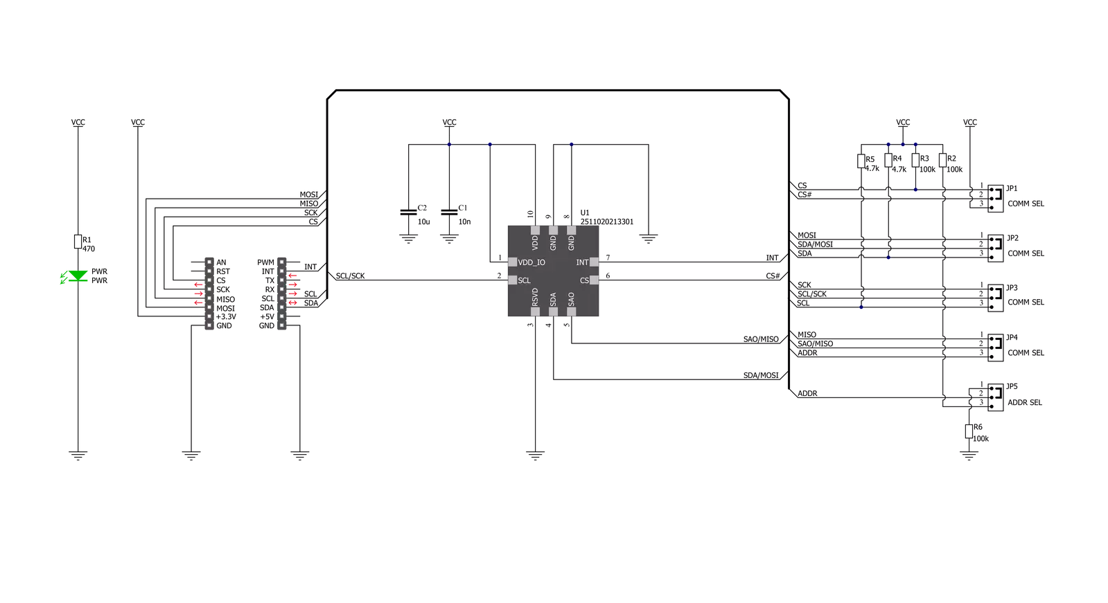
Pressure 16 Click is based on the WSEN-PADS (2511020213301), a high-resolution, ultra-compact piezoresistive absolute pressure sensor from Würth Elektronik. This MEMS-based absolute pressure sensor includes a sensing element, analog-to-digital converter, filters, and a digital interface that sends the digital pressure data to the host controller. The MEMS-based sensing element consists of piezo-resistors on a thin Si-diaphragm connected in a Wheatstone bridge configuration, which detects absolute pressure in a range of 26 up to 126kPa with selectable output data rate up to 200Hz. This measurement range corresponds to the altitude range from -1877m (below sea level) to 10,109m (above sea level). The absolute accuracy of the sensor, which is the output deviation from an ideal transfer
function over the operating pressure range, is 100Pa, which corresponds to approximately 8 meters in altitude. The piezoresistive sensing element of the WSEN-PADS is also sensitive to temperature changes and causes offset errors during pressure measurement. Therefore, real-time temperature compensation of the measured pressure plays an essential role in achieving high accuracy with the on-chip temperature sensor. Pressure 16 Click allows the use of both I2C and SPI interfaces with a maximum frequency of 100kHz in Standard and 400kHz in Fast mode for I2C and 8MHz for SPI communication. The selection can be made by positioning SMD jumpers labeled COMM SEL to an appropriate position. Note that all the jumpers' positions must be on the same side, or the Click board™ may become
unresponsive. While the I2C interface is selected, the WSEN-PADS allows the choice of the least significant bit (LSB) of its I2C slave address using the SMD jumper labeled ADDR SEL. Also, the WSEN-PADS features an interrupt signal routed on the INT pin of the mikroBUS™ socket, which indicates when a new set of measured pressure data is available, simplifying data synchronization in the digital system that uses the device. This Click board™ can be operated only with a 3.3V logic voltage level. The board must perform appropriate logic voltage level conversion before using MCUs with different logic levels. Also, it comes equipped with a library containing functions and an example code that can be used as a reference for further development.


Features overview
Development board
Fusion for TIVA v8 is a development board specially designed for the needs of rapid development of embedded applications. It supports a wide range of microcontrollers, such as different 32-bit ARM® Cortex®-M based MCUs from Texas Instruments, regardless of their number of pins, and a broad set of unique functions, such as the first-ever embedded debugger/programmer over a WiFi network. The development board is well organized and designed so that the end-user has all the necessary elements, such as switches, buttons, indicators, connectors, and others, in one place. Thanks to innovative manufacturing technology, Fusion for TIVA v8 provides a fluid and immersive working experience, allowing access
anywhere and under any circumstances at any time. Each part of the Fusion for TIVA v8 development board contains the components necessary for the most efficient operation of the same board. An advanced integrated CODEGRIP programmer/debugger module offers many valuable programming/debugging options, including support for JTAG, SWD, and SWO Trace (Single Wire Output)), and seamless integration with the Mikroe software environment. Besides, it also includes a clean and regulated power supply module for the development board. It can use a wide range of external power sources, including a battery, an external 12V power supply, and a power source via the USB Type-C (USB-C) connector.
Communication options such as USB-UART, USB HOST/DEVICE, CAN (on the MCU card, if supported), and Ethernet is also included. In addition, it also has the well-established mikroBUS™ standard, a standardized socket for the MCU card (SiBRAIN standard), and two display options for the TFT board line of products and character-based LCD. Fusion for TIVA v8 is an integral part of the Mikroe ecosystem for rapid development. Natively supported by Mikroe software tools, it covers many aspects of prototyping and development thanks to a considerable number of different Click boards™ (over a thousand boards), the number of which is growing every day.

Microcontroller Overview
MCU Card / MCU
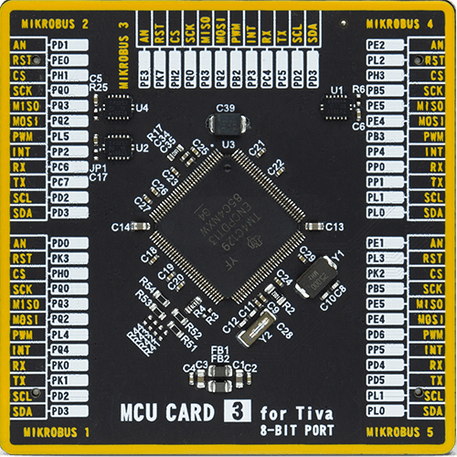
Type
8th Generation
Architecture
ARM Cortex-M4
MCU Memory (KB)
512
Silicon Vendor
Texas Instruments
Pin count
128
RAM (Bytes)
262144
Used MCU Pins
mikroBUS™ mapper
Take a closer look
Click board™ Schematic
Step by step
Project assembly

Start by selecting your development board and Click board™. Begin with the Fusion for Tiva v8 as your development board.


Software Support
Library Description
This library contains API for Pressure 16 Click driver.
Key functions:
pressure16_get_press_temp- Pressure 16 get pressure and temperature functionpressure16_set_ctrl_config- Pressure 16 set control configuration functionpressure16_get_device_id- Pressure 16 get device ID function
Open Source
Code example
The complete application code and a ready-to-use project are available through the NECTO Studio Package Manager for direct installation in the NECTO Studio. The application code can also be found on the MIKROE GitHub account.
/*!
 * @file main.c
 * @brief Pressure16 Click example
 *
 * # Description
 * This library contains API for the Pressure 16 Click driver.
 * This demo application shows an example of pressure and temperature measurement.
 *
 * The demo application is composed of two sections :
 *
 * ## Application Init
 * Initialization of I2C and SPI module and log UART.
 * After driver initialization and default settings,
 * the app display retrieves the sensor parameters
 * such as pressure and temperature.
 *
 * ## Application Task
 * This is an example that shows the use of a Pressure 16 Click board™.
 * Logs the pressure [ mbar ] and temperature [ degree Celsius ] data.
 * Results are being sent to the Usart Terminal where you can track their changes.
 *
 * @author Nenad Filipovic
 *
 */

#include "board.h"
#include "log.h"
#include "pressure16.h"

static pressure16_t pressure16;
static log_t logger;
static uint8_t device_id;

void application_init ( void )
{
    log_cfg_t log_cfg;                /**< Logger config object. */
    pressure16_cfg_t pressure16_cfg;  /**< Click config object. */

    /**
     * Logger initialization.
     * Default baud rate: 115200
     * Default log level: LOG_LEVEL_DEBUG
     * @note If USB_UART_RX and USB_UART_TX
     * are defined as HAL_PIN_NC, you will
     * need to define them manually for log to work.
     * See @b LOG_MAP_USB_UART macro definition for detailed explanation.
     */
    LOG_MAP_USB_UART( log_cfg );
    log_init( &logger, &log_cfg );
    log_info( &logger, " Application Init " );

    // Click initialization.
    pressure16_cfg_setup( &pressure16_cfg );
    PRESSURE16_MAP_MIKROBUS( pressure16_cfg, MIKROBUS_1 );
    err_t init_flag  = pressure16_init( &pressure16, &pressure16_cfg );
    if ( ( I2C_MASTER_ERROR == init_flag ) || ( SPI_MASTER_ERROR == init_flag ) )
    {
        log_error( &logger, " Application Init Error. " );
        log_info( &logger, " Please, run program again... " );

        for ( ; ; );
    }

    pressure16_default_cfg ( &pressure16 );
    Delay_ms ( 100 );
    log_info( &logger, " Application Task " );

    pressure16_get_device_id( &pressure16, &device_id );
    if ( device_id == PRESSURE16_DEVICE_ID ) {
        log_info( &logger, " Communication OK" );
    } else {
        log_info( &logger, " Communication ERROR" );
        log_info( &logger, " Please, run program again... " );

        for ( ; ; );
    }

    log_printf( &logger, "---------------------------\r\n" );
    log_printf( &logger, "      Start measuring\r\n" );
    log_printf( &logger, "---------------------------\r\n" );
    Delay_ms ( 100 );
}

void application_task ( void )
{
    static float pressure, temperature;

    pressure16_get_press_temp( &pressure16, &pressure, &temperature );
    log_printf( &logger, " Pressure    : %.2f mbar \r\n", pressure );
    log_printf( &logger, " Temperature :  %.2f C \r\n", temperature );
    log_printf( &logger, "---------------------------\r\n" );
    Delay_ms ( 1000 );
}

int main ( void )
{
    /* Do not remove this line or clock might not be set correctly. */
    #ifdef PREINIT_SUPPORTED
    preinit();
    #endif

    application_init( );

    for ( ; ; )
    {
        application_task( );
    }

    return 0;
}

// ------------------------------------------------------------------------ END
Additional Support
Resources
Category:Pressure


