Unlock data-driven decisions with precise weight measurements using AD7780 and STM32F302VC
Weight matters, accuracy counts
Published Jul 22, 2025
Click board™
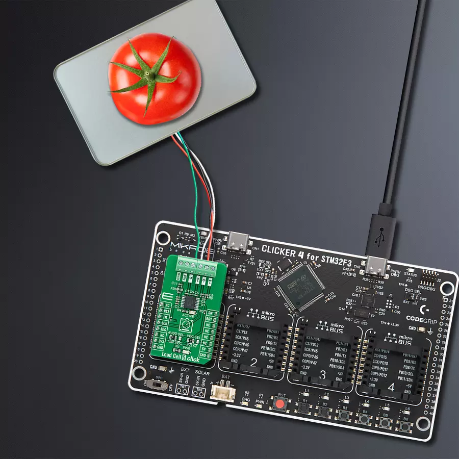
Load Cell 5 Click
Dev. board
CLICKER 4 for STM32F302VCT6
Compiler
NECTO Studio
MCU
STM32F302VC
Achieve your health goals with accurate weight tracking for personalized progress
A
A
Hardware Overview
How does it work?
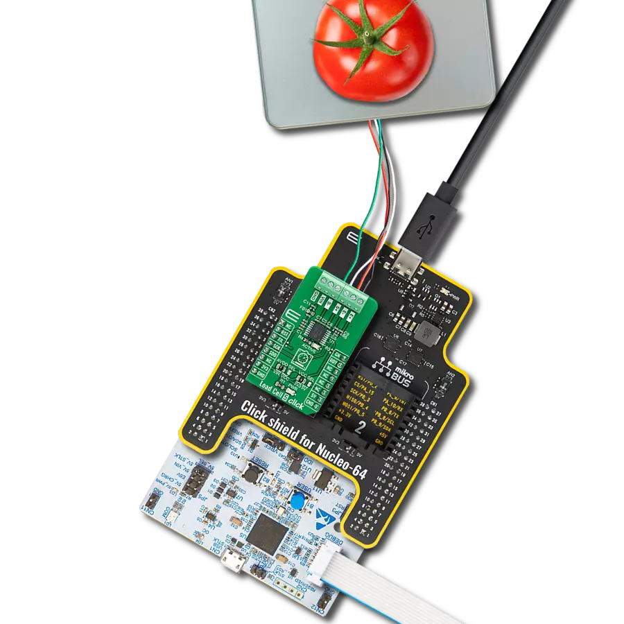
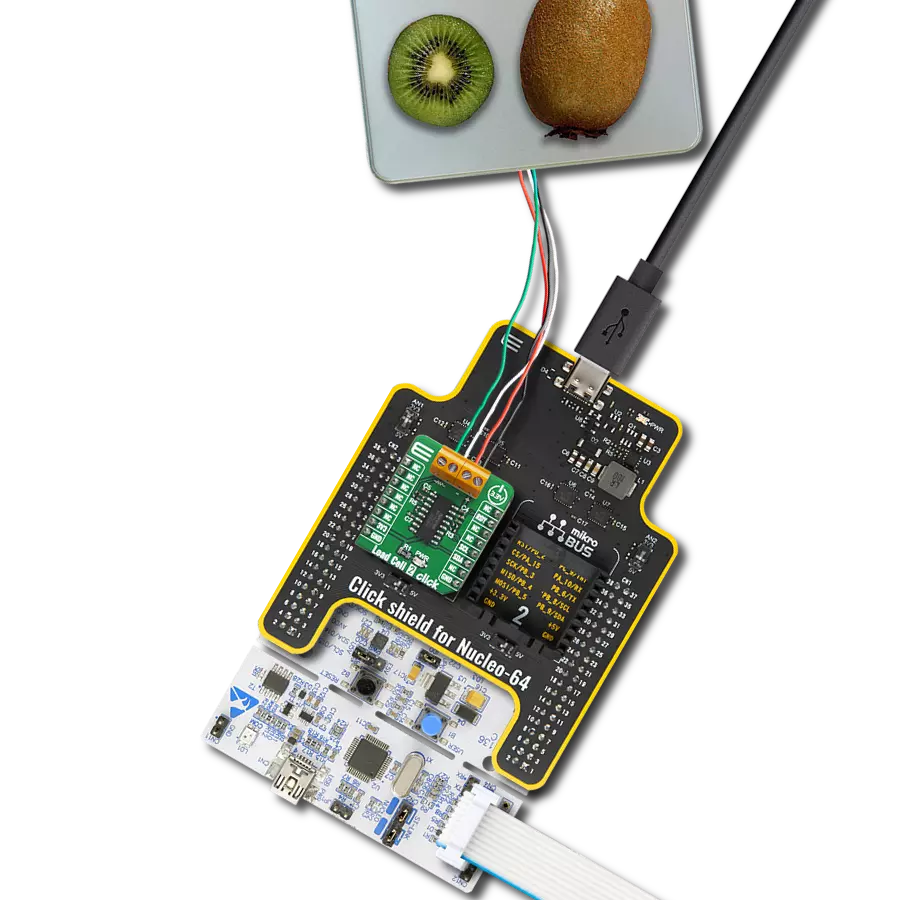
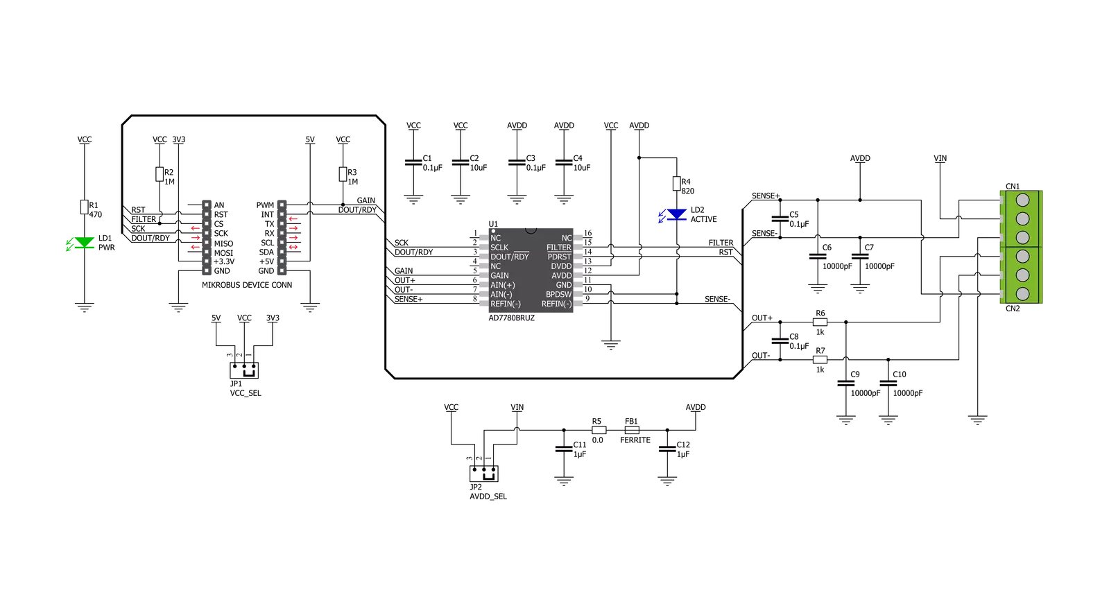
Load Cell 5 Click is based on the AD7780, a pin programmable, low power, low drift 24-bit ΣΔ ADC from Analog Devices that includes a PGA and uses an internal clock. The AD7780 typically consumes only 330μA and simplifies this weigh scale design since most of the system building blocks are already on the chip. The AD7780 has two filter options selectable via FIL pin(low state - 16.7Hz, high state - 10Hz) and a Power-Down Mode, allowing the user to switch off the power to the bridge sensor and power down the AD7780 when not converting, increasing the battery life. Since the AD7780 provides an integrated solution for weighing scales, it interfaces directly with the load cell. The only required external components, which are also on the Click board™, are filters on the analog inputs and capacitors on the reference pins for EMC purposes. The low-level signal from the load cell is amplified by the AD7780's internal PGA programmed via the PWM pin of the mikroBUS™ socket, labeled as GN, to operate with
a gain of 128 or 1. The conversions from the AD7780 are then sent to the MCU through the SPI serial interface, where the digital information is converted to weight. This Click board™ uses the 6-wire load cell configuration, which has two sense pins, ground, power supply, and two output connections. The load cell differential SENSE lines connected to the AD7780 reference inputs create a ratiometric configuration immune to low-frequency changes in the power supply excitation voltage. Those sense pins are connected to the high and low sides of the Wheatstone bridge, where voltage can be accurately measured, regardless of the voltage drop due to the wiring resistance. The AD7780 has separate analog and digital power supply pins. The analog and digital power supplies are independent of each other to be different, or the same, potentials achieved with the AVDD SEL jumper. This feature allows selecting the AD7780 power supply between an external power supply (2.7 - 5.25V) and logic
voltage levels supplied via mikroBUS™ rails. Load Cell 5 Click communicates with MCU using a standard SPI interface with a dual-purpose DOUT/RDY line. This line can function as a regular data output pin for the SPI interface or as a data-ready pin (interrupt) labeled as RDY and routed on the INT pin of the mikroBUS socket. Also, it uses the RST pin on the mikroBUS™ socket, which performs the Hardware Reset function by putting this pin in a logic low state, and a blue diode labeled as ACTIVE is used to indicate the device's Active Operational Status. This Click board™ can operate with either 3.3V or 5V logic voltage levels selected via the VCC SEL jumper. This way, both 3.3V and 5V capable MCUs can use the communication lines properly. Also, this Click board™ comes equipped with a library containing easy-to-use functions and an example code that can be used as a reference for further development.

Features overview
Development board
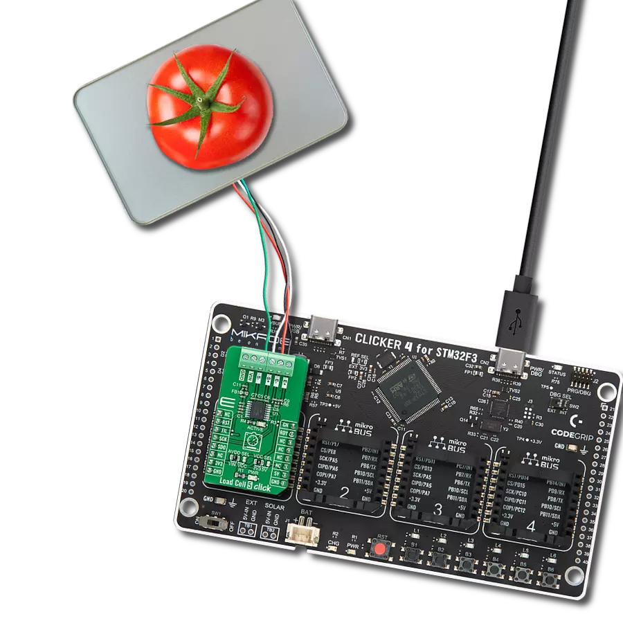
Clicker 4 for STM32F3 is a compact development board designed as a complete solution, you can use it to quickly build your own gadgets with unique functionalities. Featuring a STM32F302VCT6, four mikroBUS™ sockets for Click boards™ connectivity, power managment, and more, it represents a perfect solution for the rapid development of many different types of applications. At its core, there is a STM32F302VCT6 MCU, a powerful microcontroller by STMicroelectronics, based on the high-
performance Arm® Cortex®-M4 32-bit processor core operating at up to 168 MHz frequency. It provides sufficient processing power for the most demanding tasks, allowing Clicker 4 to adapt to any specific application requirements. Besides two 1x20 pin headers, four improved mikroBUS™ sockets represent the most distinctive connectivity feature, allowing access to a huge base of Click boards™, growing on a daily basis. Each section of Clicker 4 is clearly marked, offering an intuitive and clean interface. This makes working with the development
board much simpler and thus, faster. The usability of Clicker 4 doesn’t end with its ability to accelerate the prototyping and application development stages: it is designed as a complete solution which can be implemented directly into any project, with no additional hardware modifications required. Four mounting holes [4.2mm/0.165”] at all four corners allow simple installation by using mounting screws. For most applications, a nice stylish casing is all that is needed to turn the Clicker 4 development board into a fully functional, custom design.

Microcontroller Overview
MCU Card / MCU

Architecture
ARM Cortex-M4
MCU Memory (KB)
256
Silicon Vendor
STMicroelectronics
Pin count
100
RAM (Bytes)
40960
Used MCU Pins
mikroBUS™ mapper
Take a closer look
Click board™ Schematic
Step by step
Project assembly

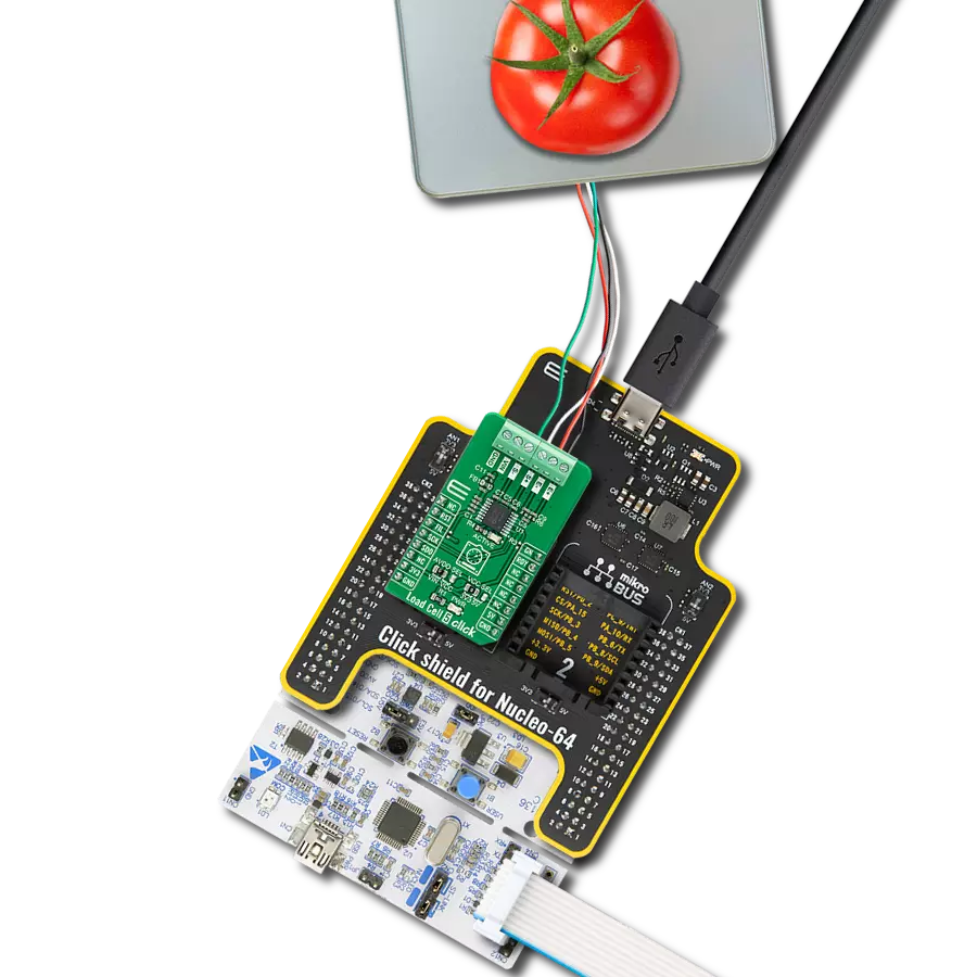
Start by selecting your development board and Click board™. Begin with the CLICKER 4 for STM32F302VCT6 as your development board.


Track your results in real time
Application Output
1. Application Output - In Debug mode, the 'Application Output' window enables real-time data monitoring, offering direct insight into execution results. Ensure proper data display by configuring the environment correctly using the provided tutorial.

2. UART Terminal - Use the UART Terminal to monitor data transmission via a USB to UART converter, allowing direct communication between the Click board™ and your development system. Configure the baud rate and other serial settings according to your project's requirements to ensure proper functionality. For step-by-step setup instructions, refer to the provided tutorial.

3. Plot Output - The Plot feature offers a powerful way to visualize real-time sensor data, enabling trend analysis, debugging, and comparison of multiple data points. To set it up correctly, follow the provided tutorial, which includes a step-by-step example of using the Plot feature to display Click board™ readings. To use the Plot feature in your code, use the function: plot(*insert_graph_name*, variable_name);. This is a general format, and it is up to the user to replace 'insert_graph_name' with the actual graph name and 'variable_name' with the parameter to be displayed.

Software Support
Library Description
This library contains API for Load Cell 5 Click driver.
Key functions:
loadcell5_set_power_mode- Load Cell 5 set power mode functionloadcell5_read_adc- Load Cell 5 reading ADC data functionloadcell5_get_weight- Load Cell 5 get weight function
Open Source
Code example
The complete application code and a ready-to-use project are available through the NECTO Studio Package Manager for direct installation in the NECTO Studio. The application code can also be found on the MIKROE GitHub account.
/*!
 * @file main.c
 * @brief LoadCell5 Click example
 *
 * # Description
 * This library contains API for Load Cell 5 Click driver.
 * The library initializes and defines the SPI bus drivers to read status and ADC data.
 * The library also includes a function for tare, calibration and weight measurement.
 *
 * The demo application is composed of two sections :
 *
 * ## Application Init
 * The initialization of SPI module, log UART, and additional pins
 * and performs the power on. Sets tare the scale, calibrate scale
 * and start measurements.
 *
 * ## Application Task
 * This is an example that demonstrates the use of the Load Cell 5 Click board.
 * The Load Cell 5 Click board can be used to measure weight,
 * shows the measurement of scales in grams [ g ].
 * Results are being sent to the Usart Terminal where you can track their changes.
 *
 * @author Nenad Filipovic
 *
 */

#include "board.h"
#include "log.h"
#include "loadcell5.h"

static loadcell5_t loadcell5;
static log_t logger;

static uint8_t status_val;
static uint32_t adc_val;

static loadcell5_data_t cell_data;
static float weight_val;

void application_init ( void ) {
    log_cfg_t log_cfg;  /**< Logger config object. */
    loadcell5_cfg_t loadcell5_cfg;  /**< Click config object. */

    /**
     * Logger initialization.
     * Default baud rate: 115200
     * Default log level: LOG_LEVEL_DEBUG
     * @note If USB_UART_RX and USB_UART_TX
     * are defined as HAL_PIN_NC, you will
     * need to define them manually for log to work.
     * See @b LOG_MAP_USB_UART macro definition for detailed explanation.
     */
    LOG_MAP_USB_UART( log_cfg );
    log_init( &logger, &log_cfg );
    log_info( &logger, " Application Init " );

    // Click initialization.

    loadcell5_cfg_setup( &loadcell5_cfg );
    LOADCELL5_MAP_MIKROBUS( loadcell5_cfg, MIKROBUS_1 );
    err_t init_flag  = loadcell5_init( &loadcell5, &loadcell5_cfg );
    if ( init_flag == SPI_MASTER_ERROR ) {
        log_error( &logger, " Application Init Error. " );
        log_info( &logger, " Please, run program again... " );

        for ( ; ; );
    }

    loadcell5_default_cfg ( &loadcell5 );
    log_info( &logger, " Application Task " );
    Delay_ms ( 500 );

    log_printf( &logger, "-------------------------\r\n");
    log_printf( &logger, "     Tare the scale :    \r\n");
    log_printf( &logger, "- - - - - - - - - - - - -\r\n");
    log_printf( &logger, " >> Remove all object << \r\n");
    log_printf( &logger, "- - - - - - - - - - - - -\r\n");
    log_printf( &logger, " In the following 10 sec \r\n");
    log_printf( &logger, " please remove all object\r\n");
    log_printf( &logger, "     from the scale.     \r\n");
    // 10 seconds delay
    Delay_ms ( 1000 );
    Delay_ms ( 1000 );
    Delay_ms ( 1000 );
    Delay_ms ( 1000 );
    Delay_ms ( 1000 );
    Delay_ms ( 1000 );
    Delay_ms ( 1000 );
    Delay_ms ( 1000 );
    Delay_ms ( 1000 );
    Delay_ms ( 1000 );

    log_printf( &logger, "-------------------------\r\n");
    log_printf( &logger, "    Start tare scales    \r\n");
    loadcell5_tare ( &loadcell5, &cell_data );
    Delay_ms ( 500 );

    log_printf( &logger, "-------------------------\r\n");
    log_printf( &logger, "   Tarring is complete   \r\n");
    log_printf( &logger, "-------------------------\r\n");
    log_printf( &logger, "    Calibrate Scale :    \r\n");
    log_printf( &logger, "- - - - - - - - - - - - -\r\n");
    log_printf( &logger, "   >>> Load etalon <<<   \r\n");
    log_printf( &logger, "- - - - - - - - - - - - -\r\n");
    log_printf( &logger, " In the following 10 sec \r\n");
    log_printf( &logger, "place 100g weight etalon\r\n");
    log_printf( &logger, "    on the scale for     \r\n");
    log_printf( &logger, "   calibration purpose.  \r\n");
    // 10 seconds delay
    Delay_ms ( 1000 );
    Delay_ms ( 1000 );
    Delay_ms ( 1000 );
    Delay_ms ( 1000 );
    Delay_ms ( 1000 );
    Delay_ms ( 1000 );
    Delay_ms ( 1000 );
    Delay_ms ( 1000 );
    Delay_ms ( 1000 );
    Delay_ms ( 1000 );

    log_printf( &logger, "-------------------------\r\n");
    log_printf( &logger, "    Start calibration    \r\n");

    if ( loadcell5_calibration ( &loadcell5, LOADCELL5_WEIGHT_100G, &cell_data ) == LOADCELL5_OK ) {
        log_printf( &logger, "-------------------------\r\n");
        log_printf( &logger, "    Calibration  Done    \r\n");

        log_printf( &logger, "- - - - - - - - - - - - -\r\n");
        log_printf( &logger, "  >>> Remove etalon <<<  \r\n");
        log_printf( &logger, "- - - - - - - - - - - - -\r\n");
        log_printf( &logger, " In the following 10 sec \r\n");
        log_printf( &logger, "   remove 100g weight   \r\n");
        log_printf( &logger, "   etalon on the scale.  \r\n");
        // 10 seconds delay
        Delay_ms ( 1000 );
        Delay_ms ( 1000 );
        Delay_ms ( 1000 );
        Delay_ms ( 1000 );
        Delay_ms ( 1000 );
        Delay_ms ( 1000 );
        Delay_ms ( 1000 );
        Delay_ms ( 1000 );
        Delay_ms ( 1000 );
        Delay_ms ( 1000 );
    }
    else {
        log_printf( &logger, "-------------------------\r\n");
        log_printf( &logger, "   Calibration  Error   \r\n");
        for ( ; ; );
    }

    log_printf( &logger, "-------------------------\r\n");
    log_printf( &logger, "   Start measurements :  \r\n");
    log_printf( &logger, "-------------------------\r\n");
}

void application_task ( void ) {
    weight_val = loadcell5_get_weight( &loadcell5, &cell_data );

    log_printf(&logger, "   Weight : %.2f g\r\n", weight_val );

    Delay_ms ( 1000 );
}

int main ( void )
{
    /* Do not remove this line or clock might not be set correctly. */
    #ifdef PREINIT_SUPPORTED
    preinit();
    #endif

    application_init( );

    for ( ; ; )
    {
        application_task( );
    }

    return 0;
}

// ------------------------------------------------------------------------ END
Additional Support
Resources
Category:Force