Accurately quantify applied forces with FSR and ATmega328P for enhanced analysis
Unveiling force measurement like never before!
Published Feb 14, 2024
Click board™
Force Click
Dev. board
Arduino UNO Rev3
Compiler
NECTO Studio
MCU
ATmega328P
Harness the power of precise force measurement to enhance quality control across various applications
A
A
Hardware Overview
How does it work?
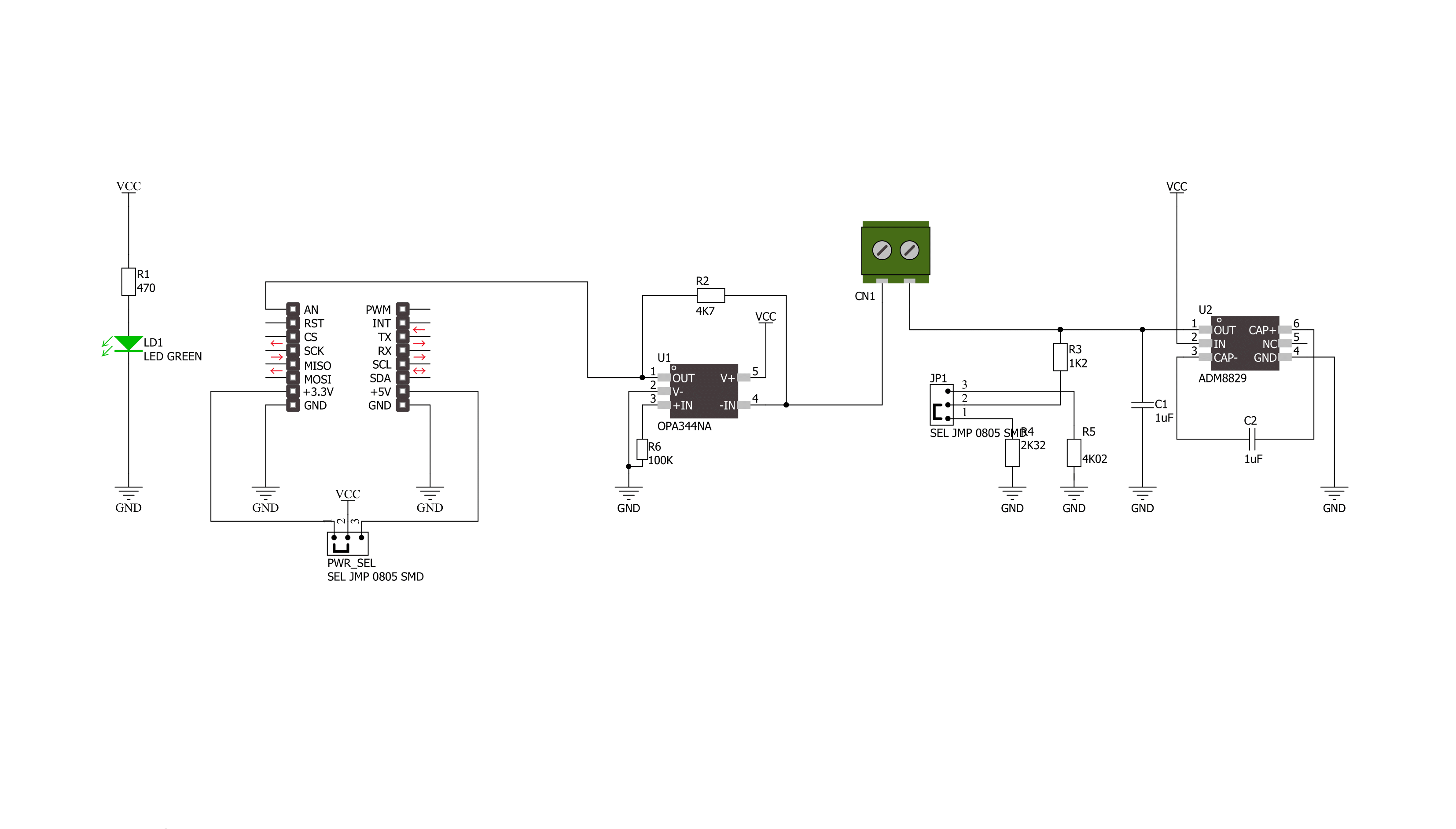
Force Click is based on the circuitry that allows the implementation of Force Sensing Resistors from Interlink Electronics. The Force Sensing Resistor is a thin sensor made of two membranes separated by a spacer around the edges. When pressed, the gap between the two membranes gets closed. This shorts the two membranes together with a resistance proportional to the applied force. This force sensitivity is optimized for human-machine interface devices, including automotive electronics, medical systems, industrial controls, and robotics. The FSR is a robust sensor with up to 10M of actuation and features a low device rise time of under 3 microseconds, as well as continuous analog force resolution. Force Click
sends analog values to the host MCU over the AN pin of the mikroBUS™ socket by using an OPA344, a low-power, single supply, rail-to-rail operational amplifier from Texas Instruments. This unity-gain stable OPAMP is ideal for driving sampling analog to digital converters. Rail-to-rail input and output swing significantly increase dynamic range, especially in low-power supply applications. The input to this OPA344NA is driven directly from the screw terminal and the force-sensing resistor. An ADM8829, a switched-capacitor voltage inverter with shutdown from Analog Devices, feeds the other side of the screw terminal and the force-sensing resistor. This charge-pump voltage inverter generates a negative power supply
from a positive input. The voltage conversion task is achieved using a switched capacitor technique using two external charge storage capacitors. An on-chip oscillator and switching network transfers charge between the charge storage capacitors. This Click board™ can operate with either 3.3V or 5V logic voltage levels selected via the PWR SEL jumper. This way, both 3.3V and 5V capable MCUs can use the communication lines properly. Also, this Click board™ comes equipped with a library containing easy-to-use functions and an example code that can be used as a reference for further development.


Features overview
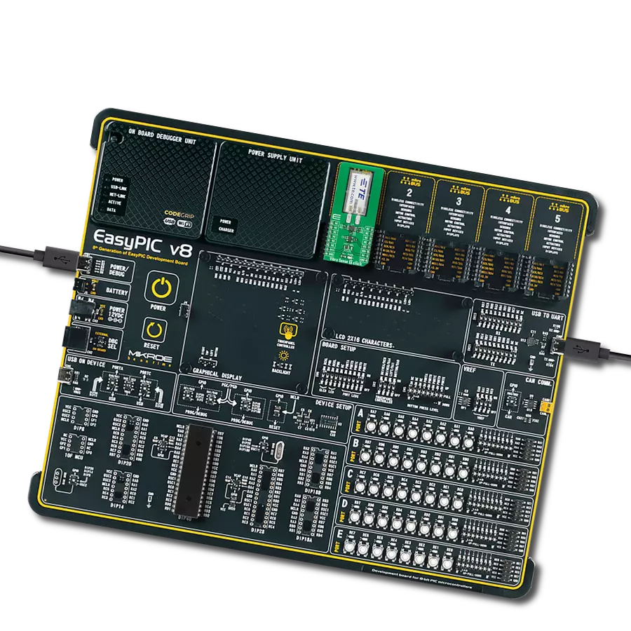
Development board
Arduino UNO is a versatile microcontroller board built around the ATmega328P chip. It offers extensive connectivity options for various projects, featuring 14 digital input/output pins, six of which are PWM-capable, along with six analog inputs. Its core components include a 16MHz ceramic resonator, a USB connection, a power jack, an
ICSP header, and a reset button, providing everything necessary to power and program the board. The Uno is ready to go, whether connected to a computer via USB or powered by an AC-to-DC adapter or battery. As the first USB Arduino board, it serves as the benchmark for the Arduino platform, with "Uno" symbolizing its status as the
first in a series. This name choice, meaning "one" in Italian, commemorates the launch of Arduino Software (IDE) 1.0. Initially introduced alongside version 1.0 of the Arduino Software (IDE), the Uno has since become the foundational model for subsequent Arduino releases, embodying the platform's evolution.

Microcontroller Overview
MCU Card / MCU

Architecture
AVR
MCU Memory (KB)
32
Silicon Vendor
Microchip
Pin count
28
RAM (Bytes)
2048
You complete me!
Accessories
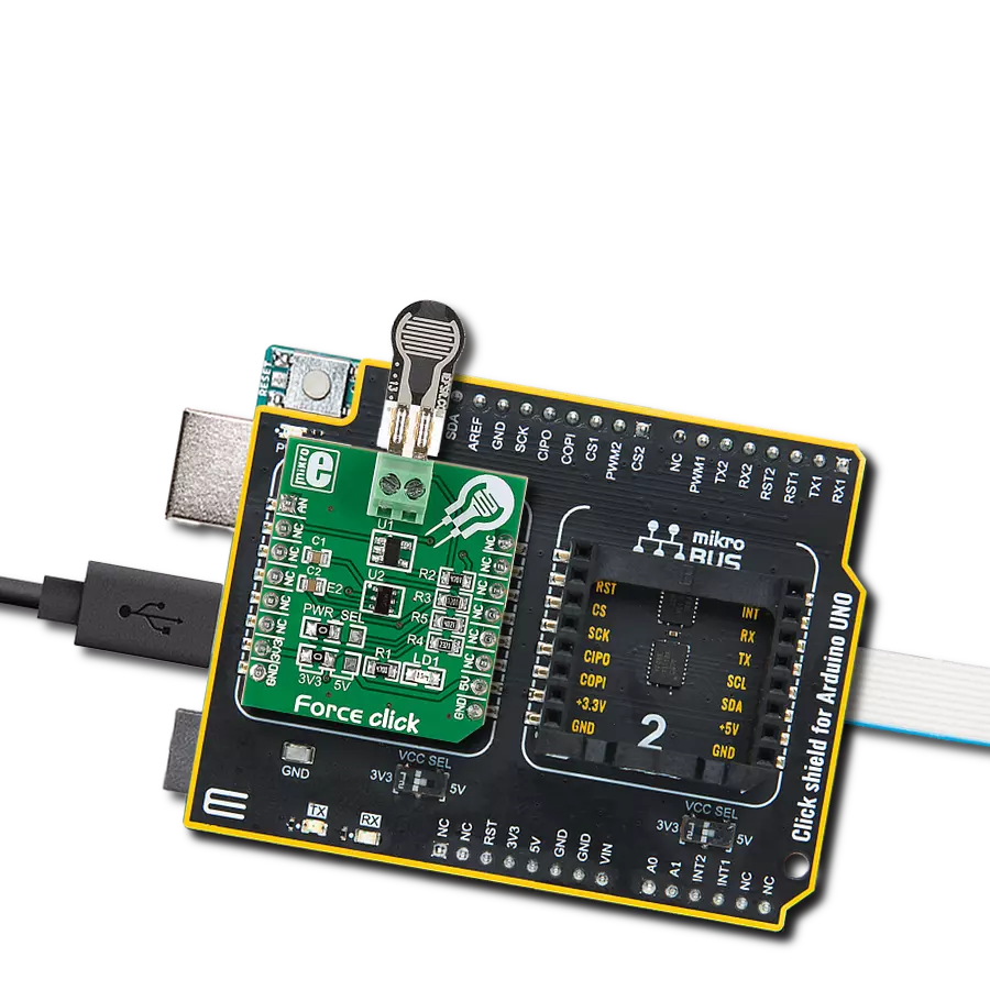
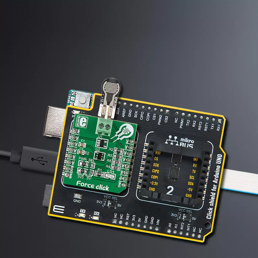
Click Shield for Arduino UNO has two proprietary mikroBUS™ sockets, allowing all the Click board™ devices to be interfaced with the Arduino UNO board without effort. The Arduino Uno, a microcontroller board based on the ATmega328P, provides an affordable and flexible way for users to try out new concepts and build prototypes with the ATmega328P microcontroller from various combinations of performance, power consumption, and features. The Arduino Uno has 14 digital input/output pins (of which six can be used as PWM outputs), six analog inputs, a 16 MHz ceramic resonator (CSTCE16M0V53-R0), a USB connection, a power jack, an ICSP header, and reset button. Most of the ATmega328P microcontroller pins are brought to the IO pins on the left and right edge of the board, which are then connected to two existing mikroBUS™ sockets. This Click Shield also has several switches that perform functions such as selecting the logic levels of analog signals on mikroBUS™ sockets and selecting logic voltage levels of the mikroBUS™ sockets themselves. Besides, the user is offered the possibility of using any Click board™ with the help of existing bidirectional level-shifting voltage translators, regardless of whether the Click board™ operates at a 3.3V or 5V logic voltage level. Once you connect the Arduino UNO board with our Click Shield for Arduino UNO, you can access hundreds of Click boards™, working with 3.3V or 5V logic voltage levels.

Used MCU Pins
mikroBUS™ mapper
Take a closer look
Click board™ Schematic
Step by step
Project assembly

Start by selecting your development board and Click board™. Begin with the Arduino UNO Rev3 as your development board.


Track your results in real time
Application Output
1. Application Output - In Debug mode, the 'Application Output' window enables real-time data monitoring, offering direct insight into execution results. Ensure proper data display by configuring the environment correctly using the provided tutorial.

2. UART Terminal - Use the UART Terminal to monitor data transmission via a USB to UART converter, allowing direct communication between the Click board™ and your development system. Configure the baud rate and other serial settings according to your project's requirements to ensure proper functionality. For step-by-step setup instructions, refer to the provided tutorial.

3. Plot Output - The Plot feature offers a powerful way to visualize real-time sensor data, enabling trend analysis, debugging, and comparison of multiple data points. To set it up correctly, follow the provided tutorial, which includes a step-by-step example of using the Plot feature to display Click board™ readings. To use the Plot feature in your code, use the function: plot(*insert_graph_name*, variable_name);. This is a general format, and it is up to the user to replace 'insert_graph_name' with the actual graph name and 'variable_name' with the parameter to be displayed.

Software Support
Library Description
This library contains API for Force Click driver.
Key functions:
force_generic_read- This function reads ADC dataforce_get_resistance- This function calculates resistance data based on the ADC inputforce_get_correction_factor- This function calculates the correction factor based on temperature and humidity data
Open Source
Code example
The complete application code and a ready-to-use project are available through the NECTO Studio Package Manager for direct installation in the NECTO Studio. The application code can also be found on the MIKROE GitHub account.
/*!
 * \file
 * \brief Force Click example
 *
 * # Description
 * This example showcases how to initialize and configure the logger and Click modules and
 * read and display ADC voltage data read from the analog pin.
 *
 * The demo application is composed of two sections :
 *
 * ## Application Init
 * This function initializes and configures the logger and Click modules.
 *
 * ## Application Task
 * This function reads and displays ADC voltage data from the analog pin every second.
 *
 * \author MikroE Team
 *
 */
// ------------------------------------------------------------------- INCLUDES

#include "board.h"
#include "log.h"
#include "force.h"

// ------------------------------------------------------------------ VARIABLES

static force_t force;
static log_t logger;

// ------------------------------------------------------ APPLICATION FUNCTIONS

void application_init ( )
{
    log_cfg_t log_cfg;
    force_cfg_t cfg;

    /**
     * Logger initialization.
     * Default baud rate: 115200
     * Default log level: LOG_LEVEL_DEBUG
     * @note If USB_UART_RX and USB_UART_TX
     * are defined as HAL_PIN_NC, you will
     * need to define them manually for log to work.
     * See @b LOG_MAP_USB_UART macro definition for detailed explanation.
     */
    LOG_MAP_USB_UART( log_cfg );
    log_init( &logger, &log_cfg );
    log_info( &logger, "---- Application Init ----" );

    log_printf( &logger, "--------------------\r\n" );
    log_printf( &logger, "    Force  Click    \r\n" );
    log_printf( &logger, "--------------------\r\n\r\n" );

    //  Click initialization.

    force_cfg_setup( &cfg );
    FORCE_MAP_MIKROBUS( cfg, MIKROBUS_1 );
    force_init( &force, &cfg );
}

void application_task ( )
{
    force_data_t tmp;

    //  Task implementation.

    tmp = force_generic_read ( &force );
    log_printf( &logger, " * ADC value : %d \r\n", tmp );
    log_printf( &logger, "--------------------- \r\n" );
    Delay_ms ( 1000 );
}

int main ( void )
{
    /* Do not remove this line or clock might not be set correctly. */
    #ifdef PREINIT_SUPPORTED
    preinit();
    #endif

    application_init( );

    for ( ; ; )
    {
        application_task( );
    }

    return 0;
}

// ------------------------------------------------------------------------ END
Additional Support
Resources
Category:Force