Design an advanced power management solution with ADP5350 and PIC32MZ2048EFM100
The ultimate battery management
Published Jul 22, 2025
Click board™
BATT-MAN 3 Click
Dev. board
Curiosity PIC32 MZ EF
Compiler
NECTO Studio
MCU
PIC32MZ2048EFM100
Streamline energy consumption, enhance battery safety, and improve overall system efficiency
A
A
Hardware Overview
How does it work?
BATT-MAN 3 Click is based on the ADP5350, an advanced battery management PMIC with inductive boost LED and three LDO regulators from Analog Devices. It combines one high-performance buck regulator for single Li-ion/Li-ion polymer battery charging (also available on the left side header labeled as BUCK), a fuel gauge, a highly programmable boost regulator for LED backlight illumination, one ultralow quiescent current low dropout (LDO) regulator, and two general-purpose LDO regulators. Besides, it supports a USB connection optimized for USB 5V input. The ADP5350 operates in trickle charge mode and constant current (CC)/constant voltage (CV) fast charge mode. It also features an internal field-effect transistor (FET) that permits battery isolation on the system power side. The ADP5350 fuel gauge is a low current-consuming solution optimal for rechargeable Li-Ion battery-powered devices. Its boost regulator operates at a 1.5MHz switching frequency. It can be employed as a constant voltage regulator or supplemental constant current regulator for multiple LED backlight drivers on the VOUT4 terminal. This LED driver can support various LED backlight
configurations, either multiple LEDs in parallel or series connected on the upper-right onboard header. This Click board™ also has a feedback-sensing for the boost regulator, which can be selected for standalone or LED operation mode by positioning the SMD jumpers labeled as MODE SEL to an appropriate position marked as STAL and LED. An additional option has been added for the users to activate or deactivate the Boost and LED part of the board by populating or removing two jumpers, R11 and R9. BATT-MAN 3 Click communicates with MCU using the standard I2C 2-Wire interface to read data and configure settings with a maximum frequency of 400kHz. Also, it uses several GPIO pins, one of which is an interrupt pin, the INT pin of the mikroBUS™ socket, used as a ‘fault’ indicator that immediately notifies the host when a fault occurs. The ADP5350 low dropout (LDO) regulators on top side terminals labeled from VOUT1 to VOUT3 are optimized to operate at low shutdown current and quiescent current to extend battery life. The device is a load switch that can be turned OFF or ON. The I2C interface enables the programmability of all parameters, including status bit readback for
operation monitoring and safety control. This Click board™ uses two LED indicators, labeled as PGOOD and BATT OK, used as power good and charging status indicator alongside the connector on the upper-left side of the board, reserved for a Li-ion/Li-ion polymer battery. PGOOD indicates a good input source, while BATT OK shows the real-time status of the battery voltage. Also, it features battery pack temperature sensing via an internal or external thermistor connected to the onboard header labeled as NTC. This sensing precludes charging when the battery pack temperature exceeds the specified range. A thermistor can be selected by positioning the SMD jumpers labeled as TMP SEL to an appropriate position marked as EXT and INT. This Click board™ can be operated only with a 5V logic voltage level. The board must perform appropriate logic voltage level conversion before using MCUs with different logic levels. Also, it comes equipped with a library containing functions and an example code that can be used, as a reference, for further development.

Features overview
Development board
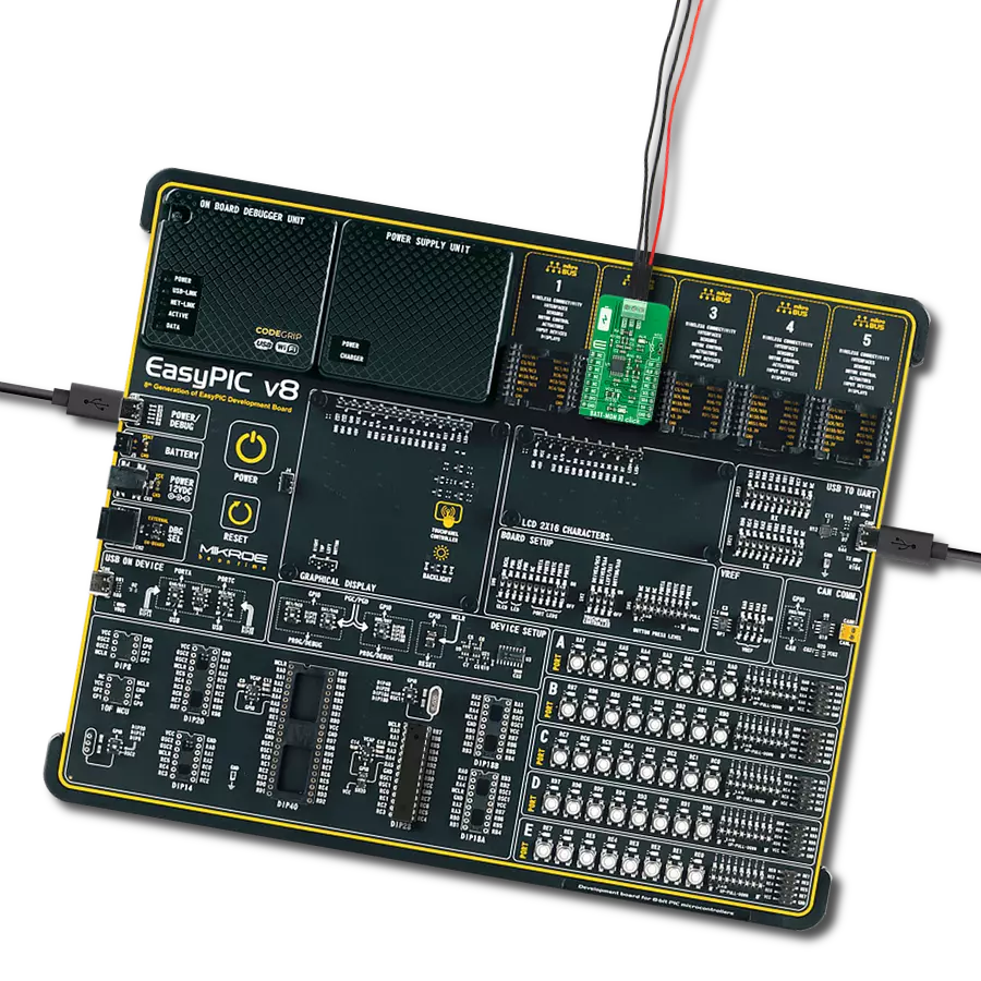
Curiosity PIC32 MZ EF development board is a fully integrated 32-bit development platform featuring the high-performance PIC32MZ EF Series (PIC32MZ2048EFM) that has a 2MB Flash, 512KB RAM, integrated FPU, Crypto accelerator, and excellent connectivity options. It includes an integrated programmer and debugger, requiring no additional hardware. Users can expand
functionality through MIKROE mikroBUS™ Click™ adapter boards, add Ethernet connectivity with the Microchip PHY daughter board, add WiFi connectivity capability using the Microchip expansions boards, and add audio input and output capability with Microchip audio daughter boards. These boards are fully integrated into PIC32’s powerful software framework, MPLAB Harmony,
which provides a flexible and modular interface to application development a rich set of inter-operable software stacks (TCP-IP, USB), and easy-to-use features. The Curiosity PIC32 MZ EF development board offers expansion capabilities making it an excellent choice for a rapid prototyping board in Connectivity, IOT, and general-purpose applications.

Microcontroller Overview
MCU Card / MCU

Architecture
PIC32
MCU Memory (KB)
2048
Silicon Vendor
Microchip
Pin count
100
RAM (Bytes)
524288
Used MCU Pins
mikroBUS™ mapper
Take a closer look
Click board™ Schematic

Step by step
Project assembly

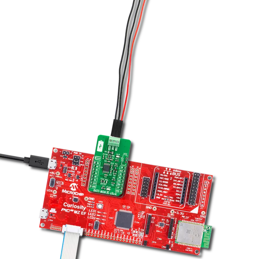
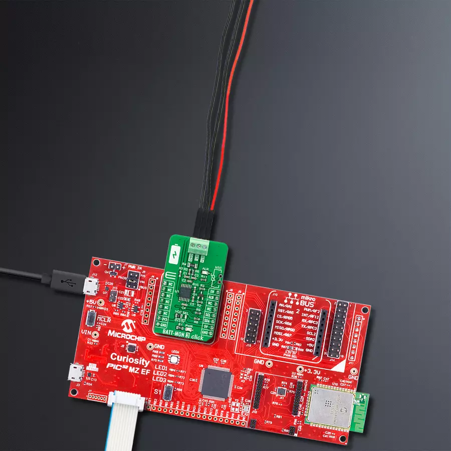
Start by selecting your development board and Click board™. Begin with the Curiosity PIC32 MZ EF as your development board.


Software Support
Library Description
This library contains API for BATT-MAN 3 Click driver.
Key functions:
battman3_get_battery_voltage- Read battery voltage levelbattman3_set_ldo_vout- Set voltage output on LDObattman3_set_charge_termination_voltage- Set charge termination voltage
Open Source
Code example
The complete application code and a ready-to-use project are available through the NECTO Studio Package Manager for direct installation in the NECTO Studio. The application code can also be found on the MIKROE GitHub account.
/*!
 * @file main.c
 * @brief BATT-MAN3 Click example
 *
 * # Description
 * This example showcases ability of device to charge battery,
 * and outputs and supply 4 different devices with 3 LDO's and
 * 1 boost channel.
 *
 * The demo application is composed of two sections :
 *
 * ## Application Init
 * Initialization of the communication modules(UART, I2C) and 3 additional
 * input pins(power good, battery ok, and interrupt). Configures device
 * to enable charging, battery voltage monitoring, sets charging termination
 * to 3.7V, charging threshold to 3.1V and dead battery to 2.5V. Enables all
 * 3 LDO's( channel 1 -> 3.3V, channel 2 -> 1.5V, and channel 3 -> 2.5V ).
 *
 * ## Application Task
 * Reads battery voltage level and logs it. Besides that reads status and logs
 * every change on charging and battery status. If power good flag occurs(PGD
 * pin goes low) disables LDO's, and reenables them when battery is full(when
 * battery reaches charging termination voltage).
 *
 * @author Luka Filipovic
 *
 */

#include "board.h"
#include "log.h"
#include "battman3.h"

/**
 * @brief BATT-MAN 3 Click LOG delay.
 * @details Macro that specifies delay between logs of battery voltage.
 */
#define LOG_THRESHOLD_1SEC 10
#define LOG_THRESHOLD_3SEC 30
#define LOG_THRESHOLD_5SEC 50

static battman3_t battman3;
static log_t logger;

/**
 * @brief Parse charge status.
 * @details This function reads charge status 1 and 2
 * and logs @b CHAGER_STATUS and @b BATTERY_STATUS on change.
 * @return Nothing.
 */
static void battman3_charge_status ( void );

/**
 * @brief Enable/Disable all 3 LDO's.
 * @details This function sets state of all 3 LDO's.
 * @param[in] enable : Enable/Disable.
 * @return Nothing.
 */
static void battman3_ldo( uint8_t enable );

void application_init ( void )
{
    log_cfg_t log_cfg;  /**< Logger config object. */
    battman3_cfg_t battman3_cfg;  /**< Click config object. */

    /**
     * Logger initialization.
     * Default baud rate: 115200
     * Default log level: LOG_LEVEL_DEBUG
     * @note If USB_UART_RX and USB_UART_TX
     * are defined as HAL_PIN_NC, you will
     * need to define them manually for log to work.
     * See @b LOG_MAP_USB_UART macro definition for detailed explanation.
     */
    LOG_MAP_USB_UART( log_cfg );
    log_init( &logger, &log_cfg );
    log_info( &logger, " Application Init " );

    // Click initialization.
    battman3_cfg_setup( &battman3_cfg );
    BATTMAN3_MAP_MIKROBUS( battman3_cfg, MIKROBUS_1 );
    if ( I2C_MASTER_ERROR == battman3_init( &battman3, &battman3_cfg ) )
    {
        log_error( &logger, " Communication init." );
        for ( ; ; );
    }

    if ( BATTMAN3_ERROR == battman3_default_cfg ( &battman3 ) )
    {
        log_error( &logger, " Default configuration." );
        for ( ; ; );
    }

    uint8_t temp_data = 0;

    battman3_reg_read( &battman3, BATTMAN3_REG_MANUFACTURE_AND_MODEL_ID, &temp_data );
    log_printf( &logger, " > ID: 0x%.2X\r\n", ( uint16_t )temp_data );
    battman3_reg_read( &battman3, BATTMAN3_REG_SILICON_REVSION, &temp_data );
    log_printf( &logger, " > REV: 0x%.2X\r\n", ( uint16_t )temp_data );

    //Charging voltage termination
    battman3_set_charge_termination_voltage( &battman3, 3.7 );
    //Charging voltage threshold
    battman3_set_charge_voltage_threshold( &battman3, BATTMAN3_VTRK_DEAD_2p5V, 3.1 );
    //LDO 1
    battman3_set_ldo_state( &battman3, BATTMAN3_LDO1, BATTMAN3_ENABLE );
    battman3_set_ldo_vout( &battman3, BATTMAN3_LDO1, BATTMAN3_LDO_3p30V );
    //LDO 2
    battman3_set_ldo_state( &battman3, BATTMAN3_LDO2, BATTMAN3_ENABLE );
    battman3_set_ldo_vout( &battman3, BATTMAN3_LDO2, BATTMAN3_LDO_1p50V );
    //LDO 3
    battman3_set_ldo_state( &battman3, BATTMAN3_LDO3, BATTMAN3_ENABLE );
    battman3_set_ldo_vout( &battman3, BATTMAN3_LDO3, BATTMAN3_LDO_2p50V );

    log_info( &logger, " Application Task " );
    Delay_ms ( 500 );
}

void application_task ( void )
{
    static uint8_t counter = 0;
    static uint8_t ldo_enable = 1;
    float vbat = 0;

    if ( !battman3_get_power_good( &battman3 ) && ldo_enable )
    {
        battman3_ldo( BATTMAN3_DISABLE );
        log_printf( &logger, " > Power is not good - LDO disabled\r\n" );
        ldo_enable = 0;
    }
    else if ( battman3_get_power_good( &battman3 ) && !ldo_enable )
    {
        battman3_ldo( BATTMAN3_ENABLE );
        log_printf( &logger, " > Power is good - LDO enabled\r\n" );
        ldo_enable = 1;
    }

    battman3_charge_status( );

    if ( counter >= LOG_THRESHOLD_3SEC )
    {
        counter = 0;
        battman3_get_battery_voltage( &battman3, &vbat );
        log_printf( &logger, " > Battery voltage: %.2f\r\n", vbat );
        log_printf( &logger, "****************************************************\r\n" );
    }
    counter++;
    Delay_ms ( 100 );
}

int main ( void )
{
    /* Do not remove this line or clock might not be set correctly. */
    #ifdef PREINIT_SUPPORTED
    preinit();
    #endif

    application_init( );

    for ( ; ; )
    {
        application_task( );
    }

    return 0;
}

static void battman3_charge_status ( void )
{
    static uint8_t charge_status1 = 0;
    static uint8_t charge_status2 = 0;
    uint8_t temp_data = 0;
    battman3_reg_read( &battman3, BATTMAN3_REG_CHARGER_STATUS1, &temp_data );
    temp_data &= 0x7;
    if ( charge_status1 != temp_data )
    {
        charge_status1 = temp_data;
        switch ( charge_status1 )
        {
            case BATTMAN3_CHARGE_STATUS1_OFF:
            {
                log_printf( &logger, " > Charge status: off\r\n" );
                break;
            }
            case BATTMAN3_CHARGE_STATUS1_TRICLE_CHARGE:
            {
                log_printf( &logger, " > Charge status: tricle charge\r\n" );
                break;
            }
            case BATTMAN3_CHARGE_STATUS1_FAST_CHARGE_CC:
            {
                log_printf( &logger, " > Charge status: fast charge(CC mode)\r\n" );
                break;
            }
            case BATTMAN3_CHARGE_STATUS1_FAST_CHARGE_CV:
            {
                battman3_ldo( BATTMAN3_ENABLE );/*< Battery is full reenable LDO's*/
                log_printf( &logger, " > Charge status: fast charge(CV mode)\r\n" );
                break;
            }
            case BATTMAN3_CHARGE_STATUS1_CHARGE_COMPLETE:
            {
                log_printf( &logger, " > Charge status: charge complete\r\n" );
                break;
            }
            case BATTMAN3_CHARGE_STATUS1_SUSPEND:
            {
                log_printf( &logger, " > Charge status: suspend\r\n" );
                break;
            }
            case BATTMAN3_CHARGE_STATUS1_TIMER_EXPIRED:
            {
                log_printf( &logger, " > Charge status: ticle, fast or safety charge timer expired\r\n" );
                break;
            }
            case BATTMAN3_CHARGE_STATUS1_BATTERY_DETECTION:
            {
                log_printf( &logger, " > Charge status: battery detection\r\n" );
                break;
            }
            default:
            {
                log_error( &logger, " Status." );
                break;
            }
        }
    }
    battman3_reg_read( &battman3, BATTMAN3_REG_CHARGER_STATUS2, &temp_data );
    temp_data &= 0x07;
    if ( charge_status2 != temp_data )
    {
        charge_status2 = temp_data;
        switch ( charge_status2 )
        {
            case BATTMAN3_CHARGE_STATUS2_BATTERY_MONITOR_OFF:
            {
                log_printf( &logger, " > Battery monitor off\r\n" );
                break;
            }
            case BATTMAN3_CHARGE_STATUS2_NO_BATTERY:
            {
                log_printf( &logger, " > No battery\r\n" );
                break;
            }
            case BATTMAN3_CHARGE_STATUS2_VBSNS_LESSTHEN_VTRK:
            {
                log_printf( &logger, " > Battery voltage less then trickle threshold\r\n" );
                break;
            }
            case BATTMAN3_CHARGE_STATUS2_VBSNS_MIDDLE_VRK_VWEAK:
            {
                log_printf( &logger, " > Battery voltage in middle between tricle and weak threshold\r\n" );
                break;
            }
            case BATTMAN3_CHARGE_STATUS2_VBSNS_MORETHEN_VWEAK:
            {
                log_printf( &logger, " > Battery voltage more then weak threshold\r\n" );
                break;
            }
            default:
            {
                log_error( &logger, " Status." );
                break;
            }
        }
    }
}

static void battman3_ldo( uint8_t enable )
{
    battman3_set_ldo_state( &battman3, BATTMAN3_LDO1, enable );
    battman3_set_ldo_state( &battman3, BATTMAN3_LDO2, enable );
    battman3_set_ldo_state( &battman3, BATTMAN3_LDO3, enable );
}

// ------------------------------------------------------------------------ END
Additional Support
Resources
Category:Buck-Boost