Unleash efficiency and performance with step-down/step-up regulator based on MIC23099 and PIC32MZ1024EFH064
AA/AAA cell buck-boost

Published Aug 01, 2023
Click board™
MIC23099 Click
Dev. board
PIC32MZ clicker
Compiler
NECTO Studio
MCU
PIC32MZ1024EFH064
Efficiently manage the power supply for electronic devices that require a voltage different from that provided by a single AA or AAA battery
A
A
Hardware Overview
How does it work?
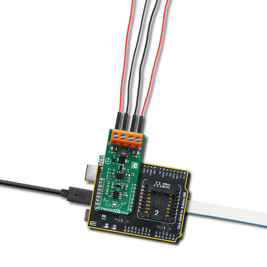
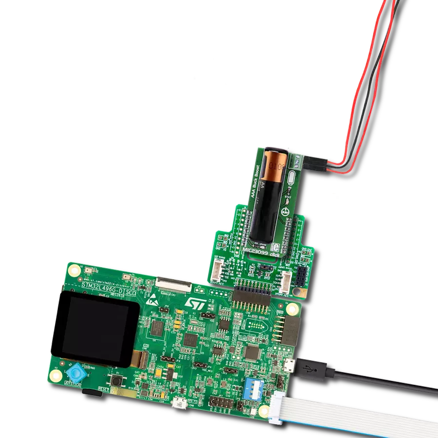
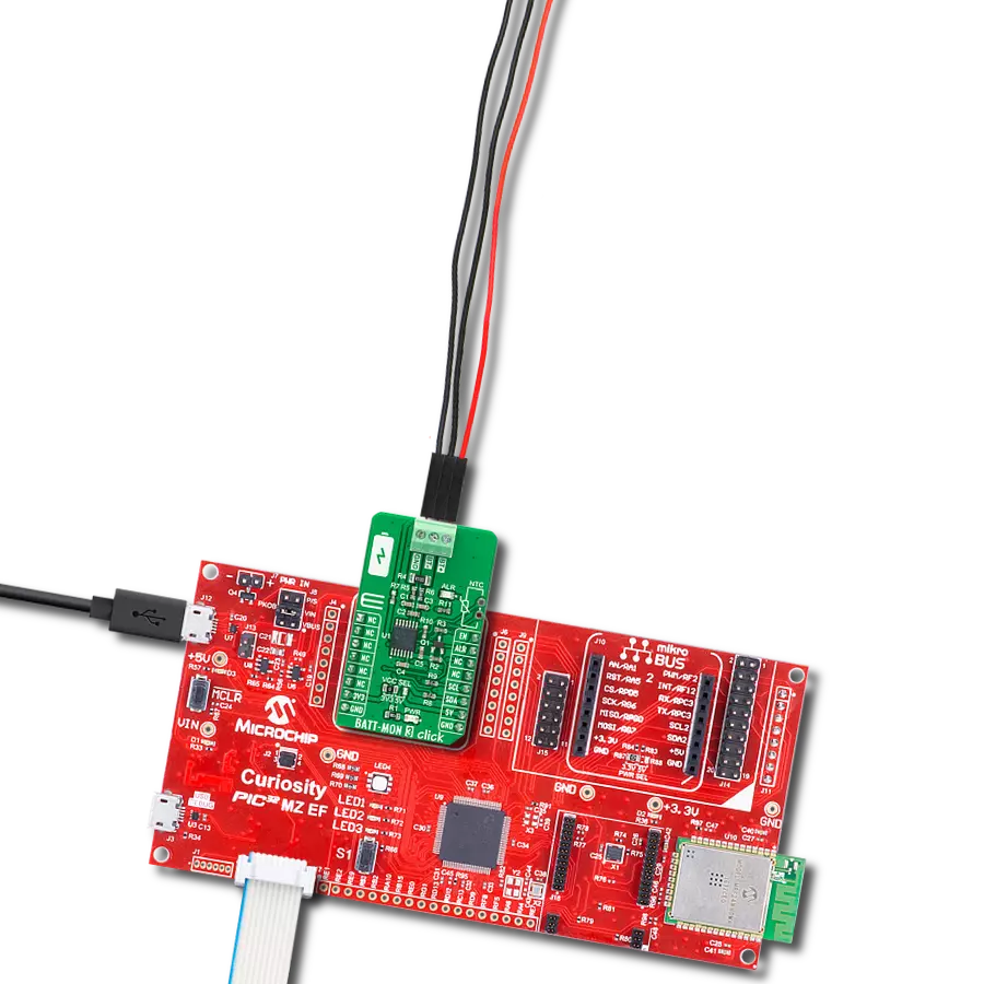
MIC23099 Click is based on the MIC23099, a single AA/AAA cell step-down/step-up regulator with battery monitoring from Microchip. This Click is designed to run on a 3.3V power supply. It communicates with the target microcontroller over the following pins on the mikroBUS™ line: CS, INT. MIC23099 Click has three screw terminals (Buck 1V, GND, and Boost 3V3) which are outputs
for connecting some external consumers. The low-battery level is indicated by an onboard STAT LED. The MIC23099 is not a battery charger but needs a battery to work properly. The battery is not included. The MIC23099 is a high-efficiency, low-noise, dual output, integrated power management solution for single-cell alkaline or NiMH battery applications. Both converters are
designed to operate with a minimum switching frequency of 80 kHz for the buck and 100 kHz for the boost to minimize switching artifacts in the audio band. The high-current boost has a maximum switching frequency of 1 MHz, minimizing the solution footprint. The MIC23099 incorporates both battery management functions and fault protection.


Features overview
Development board
PIC32MZ Clicker is a compact starter development board that brings the flexibility of add-on Click boards™ to your favorite microcontroller, making it a perfect starter kit for implementing your ideas. It comes with an onboard 32-bit PIC32MZ microcontroller with FPU from Microchip, a USB connector, LED indicators, buttons, a mikroProg connector, and a header for interfacing with external electronics. Thanks to its compact design with clear and easy-recognizable silkscreen markings, it provides a fluid and immersive working experience, allowing access anywhere and under
any circumstances. Each part of the PIC32MZ Clicker development kit contains the components necessary for the most efficient operation of the same board. In addition to the possibility of choosing the PIC32MZ Clicker programming method, using USB HID mikroBootloader, or through an external mikroProg connector for PIC, dsPIC, or PIC32 programmer, the Clicker board also includes a clean and regulated power supply module for the development kit. The USB Micro-B connection can provide up to 500mA of current, which is more than enough to operate all onboard
and additional modules. All communication methods that mikroBUS™ itself supports are on this board, including the well-established mikroBUS™ socket, reset button, and several buttons and LED indicators. PIC32MZ Clicker is an integral part of the Mikroe ecosystem, allowing you to create a new application in minutes. Natively supported by Mikroe software tools, it covers many aspects of prototyping thanks to a considerable number of different Click boards™ (over a thousand boards), the number of which is growing every day.

Microcontroller Overview
MCU Card / MCU

Architecture
PIC32
MCU Memory (KB)
1024
Silicon Vendor
Microchip
Pin count
64
RAM (Bytes)
524288
Used MCU Pins
mikroBUS™ mapper
Take a closer look
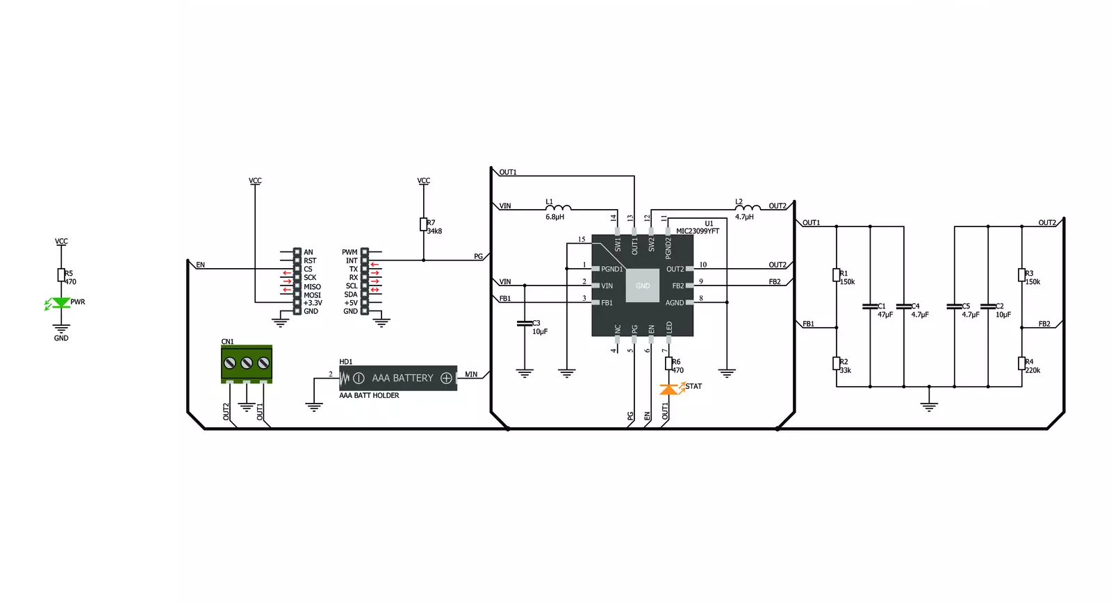
Click board™ Schematic
Step by step
Project assembly

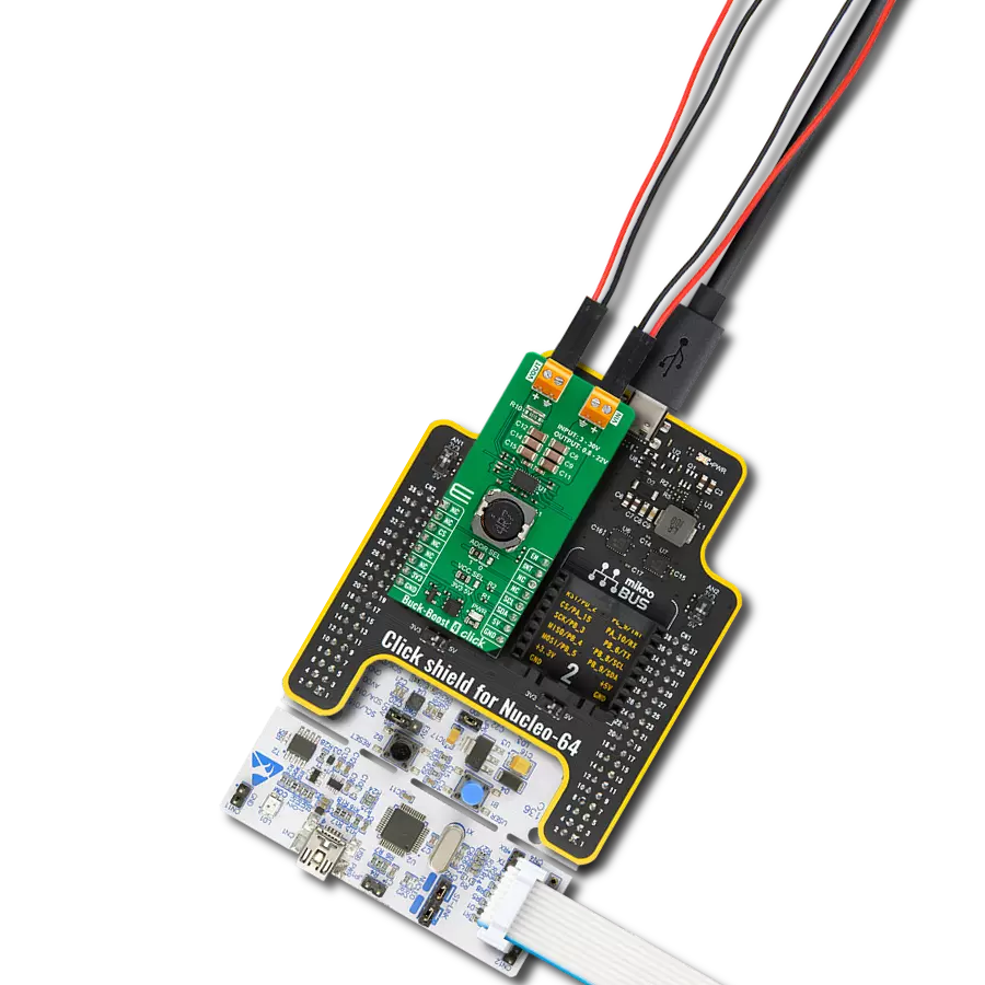
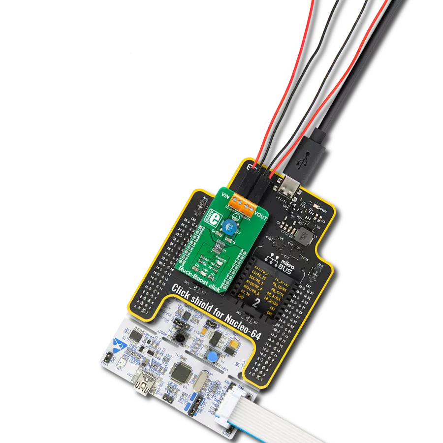
Start by selecting your development board and Click board™. Begin with the PIC32MZ clicker as your development board.


Software Support
Library Description
This library contains API for MIC23099 Click driver.
Key functions:
mic23099_default_cfg- This function executes default configuration for MIC23099 Clickmic23099_check_power_good- This function checks the state of Power Good output pin
Open Source
Code example
The complete application code and a ready-to-use project are available through the NECTO Studio Package Manager for direct installation in the NECTO Studio. The application code can also be found on the MIKROE GitHub account.
/*!
 * \file
 * \brief MIC23099 Click example
 *
 * # Description
 * MIC23099 Click represent single AA/AAA cell step-down/step-up regulator
 * with battery monitoring.
 *
 * The demo application is composed of two sections :
 *
 * ## Application Init
 * Application Init performs Logger and Click initialization.
 *
 * ## Application Task
 * This example demonstrates the use of MIC23099 Click board by checking
 * the state of power good pin and sends note via UART Terminal
 * if the state is low.
 *
 * \author Mihajlo Djordjevic
 *
 */
// ------------------------------------------------------------------- INCLUDES

#include "board.h"
#include "log.h"
#include "mic23099.h"

// ------------------------------------------------------------------ VARIABLES

static mic23099_t mic23099;
static log_t logger;

static uint8_t new_stat;
static uint8_t old_stat;

// ------------------------------------------------------- ADDITIONAL FUNCTIONS


// ------------------------------------------------------ APPLICATION FUNCTIONS

void application_init ( void )
{
    log_cfg_t log_cfg;
    mic23099_cfg_t cfg;

    /**
     * Logger initialization.
     * Default baud rate: 115200
     * Default log level: LOG_LEVEL_DEBUG
     * @note If USB_UART_RX and USB_UART_TX
     * are defined as HAL_PIN_NC, you will
     * need to define them manually for log to work.
     * See @b LOG_MAP_USB_UART macro definition for detailed explanation.
     */
    LOG_MAP_USB_UART( log_cfg );
    log_init( &logger, &log_cfg );
    log_printf( &logger, "--------------------------\r\n" );
    log_printf( &logger, "     Application  Init\r\n" );
    Delay_ms ( 1000 );

    //  Click initialization.

    mic23099_cfg_setup( &cfg );
    MIC23099_MAP_MIKROBUS( cfg, MIKROBUS_1 );
    mic23099_init( &mic23099, &cfg );

    log_printf( &logger, "--------------------------\r\n" );
    log_printf( &logger, " ---- MIC23099 Click ---- \r\n" );
    log_printf( &logger, "--------------------------\r\n" );
    Delay_ms ( 1000 );

    mic23099_default_cfg( &mic23099 );
    Delay_ms ( 1000 );

    new_stat = MIC23099_DISABLE;
    old_stat = MIC23099_ENABLE;

    log_printf( &logger, " -- Initialization done --\r\n" );
    log_printf( &logger, "--------------------------\r\n" );
    Delay_ms ( 1000 );
}

void application_task ( void )
{
    new_stat = mic23099_check_power_good( &mic23099 );

    if ( new_stat == MIC23099_ENABLE && old_stat == MIC23099_DISABLE )
    {
        old_stat = MIC23099_ENABLE;
    }

    if ( new_stat == MIC23099_DISABLE && old_stat == MIC23099_ENABLE )
    {
        log_printf( &logger, " Change  battery  and  reset. \r\n" );
        log_printf( &logger, "------------------------------\r\n" );
        old_stat = MIC23099_DISABLE;
    }
}

int main ( void )
{
    /* Do not remove this line or clock might not be set correctly. */
    #ifdef PREINIT_SUPPORTED
    preinit();
    #endif

    application_init( );

    for ( ; ; )
    {
        application_task( );
    }

    return 0;
}

// ------------------------------------------------------------------------ END