Heart check-ins made easy with BH1790GLC and TM4C129ENCPDT
Your heart, your health

Published Jul 01, 2023
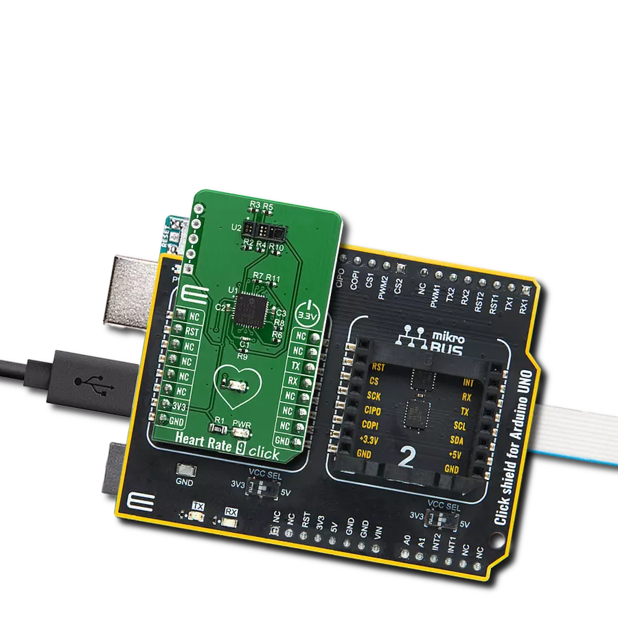
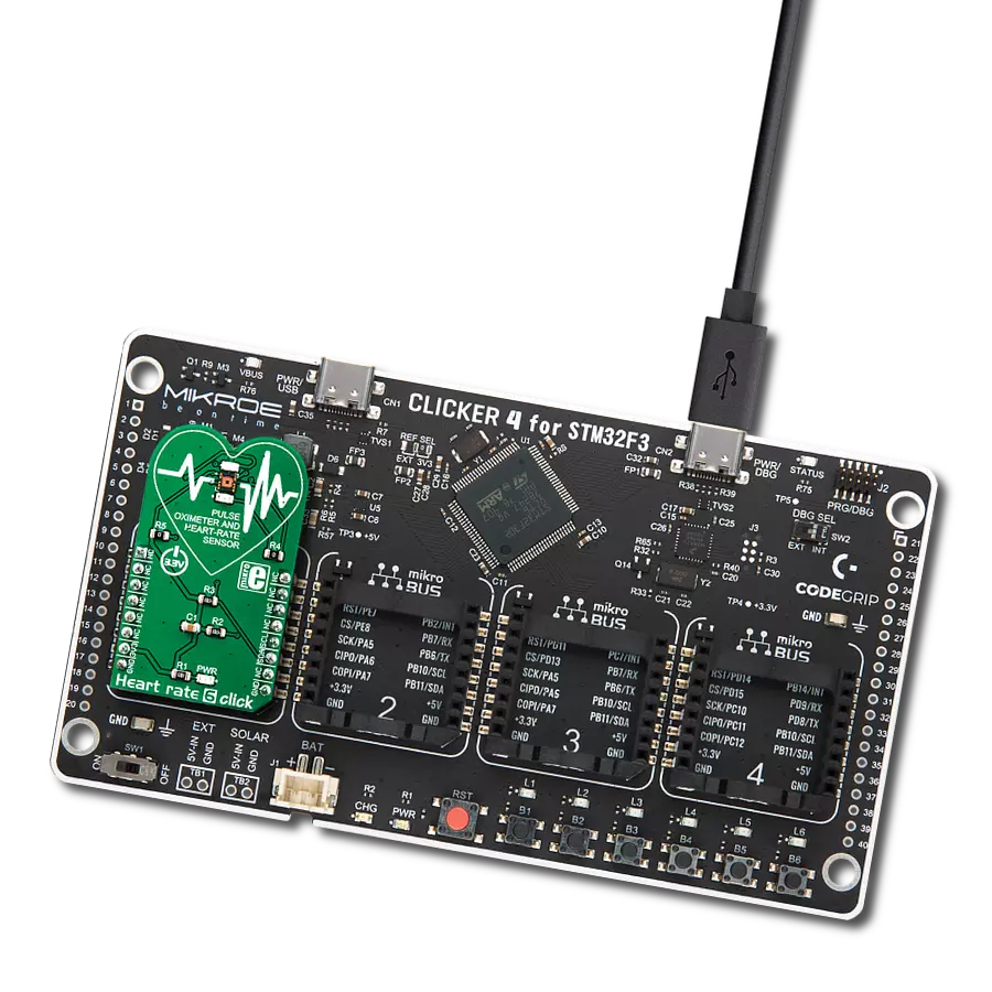
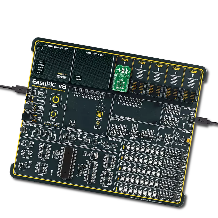
Click board™
Heart rate 6 click
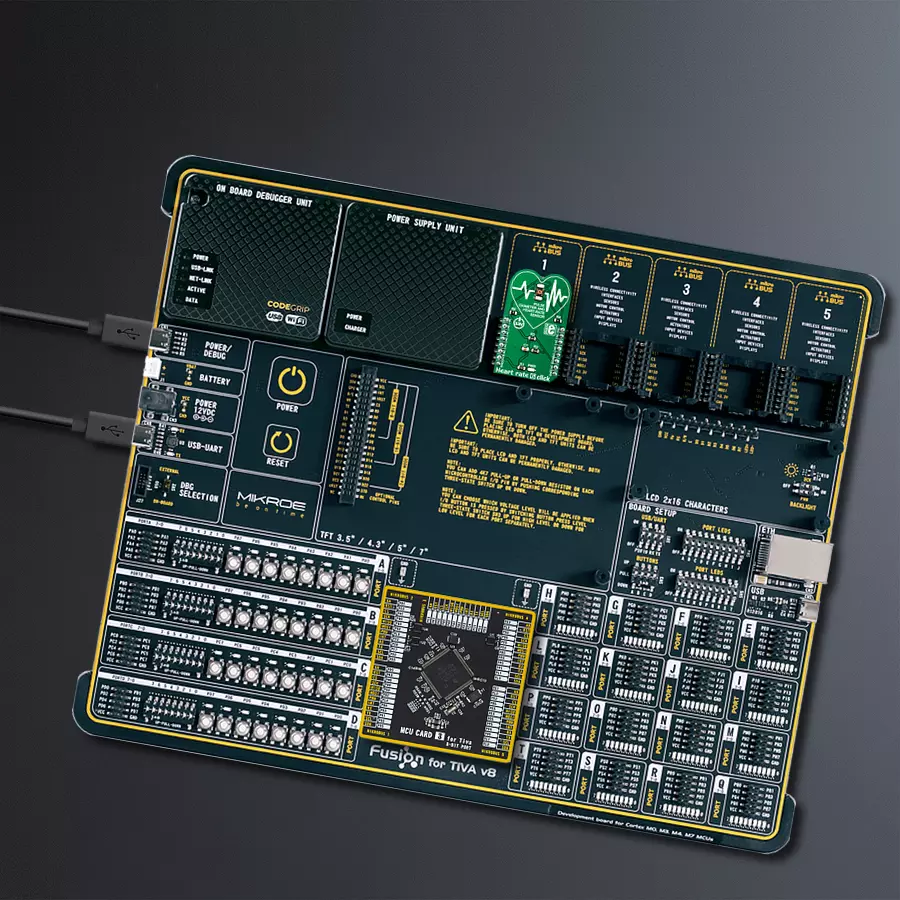
Dev. board
Fusion for Tiva v8
Compiler
NECTO Studio
MCU
TM4C129ENCPDT
Upgrade your solution's heart rate monitoring capabilities with an advanced and versatile heart rate sensor
A
A
Hardware Overview
How does it work?
Heart rate 6 Click is based on the BH1790GLC, a monolithically integrated sensor for heart rate monitoring, from ROHM Semiconductor. This IC is a highly integrated optical sensor well-suited for performing PPM measurements. Due to the large integration scale of this sensor, as well as its low power consumption, it is perfectly suited to be used on a wearable IoT device. However, being a Click board™, Heart rate 6 Click allows easy evaluation and rapid application and firmware development. Two green LEDs are driven by the integrated LED driving section of the BH1790GLC sensor, with a programmable pulsating frequency of 64Hz or 128Hz. The LED current can also be programmed from 0 to 60 mA. Finally, there are two settings for the pulse duration: 0.3ms and 0.6ms. These two values affect the duty cycle of the LED pulses. Optimal readings can be achieved by balancing these three parameters: the current amount through the LED (brightness), the speed
of the light pulses (LED frequency), and the pulse width (0.3ms or 0.6ms) The reflected light burst is detected by a sensing element as a photo-diode, sampled by a low-noise 16-bit A/D converter. The photo-diode is located behind two light filters which pass only a narrow band of green light in the range from 520nm to 560nm, with 0.8X reduction with respect to the center frequency. The top filter is an IRCUT filter that prevents the influence of the IR light, while the second filtering layer only passes the green light. This allows an even broader color range of LEDs to be used, reducing the overall cost of the design. However, Heart rate 6 Click uses the KingBright super bright clear green LEDs, with a spectral response that is closely matched to the passband properties of the optical filter. This allows most of the LED energy to be used, further improving the power consumption profile. Two output registers contain the 16-bit measurement as two 8-bit words.
The upper and the lower 8-bit registers contain the measurement data, which can be retrieved over the standard I2C interface. The host MCU can read these registers in cycles of 1/32 sec or 1/64 sec, depending on the BH1790GLC settings. The datasheet of the BH1790GLC contains the correct algorithms, which describe the measurement process in more detail. However, the Click board™ comes with the library, which contains functions that allow measurements to be performed with minimum effort. The I2C pins of the BH1790GLC sensor are routed to the respective mikroBUS™ I2C pins. The I2C bus lines are already equipped with two pull-up resistors, which, together with the two external LEDs, are the only components required by the BH1790GLC sensor. Pull-up resistors are connected to the 3.3V power rail so that the Click board™ can be used only with MCUs that use logic levels up to 3.3V for communication.


Features overview
Development board
Fusion for TIVA v8 is a development board specially designed for the needs of rapid development of embedded applications. It supports a wide range of microcontrollers, such as different 32-bit ARM® Cortex®-M based MCUs from Texas Instruments, regardless of their number of pins, and a broad set of unique functions, such as the first-ever embedded debugger/programmer over a WiFi network. The development board is well organized and designed so that the end-user has all the necessary elements, such as switches, buttons, indicators, connectors, and others, in one place. Thanks to innovative manufacturing technology, Fusion for TIVA v8 provides a fluid and immersive working experience, allowing access
anywhere and under any circumstances at any time. Each part of the Fusion for TIVA v8 development board contains the components necessary for the most efficient operation of the same board. An advanced integrated CODEGRIP programmer/debugger module offers many valuable programming/debugging options, including support for JTAG, SWD, and SWO Trace (Single Wire Output)), and seamless integration with the Mikroe software environment. Besides, it also includes a clean and regulated power supply module for the development board. It can use a wide range of external power sources, including a battery, an external 12V power supply, and a power source via the USB Type-C (USB-C) connector.
Communication options such as USB-UART, USB HOST/DEVICE, CAN (on the MCU card, if supported), and Ethernet is also included. In addition, it also has the well-established mikroBUS™ standard, a standardized socket for the MCU card (SiBRAIN standard), and two display options for the TFT board line of products and character-based LCD. Fusion for TIVA v8 is an integral part of the Mikroe ecosystem for rapid development. Natively supported by Mikroe software tools, it covers many aspects of prototyping and development thanks to a considerable number of different Click boards™ (over a thousand boards), the number of which is growing every day.

Microcontroller Overview
MCU Card / MCU

Type
8th Generation
Architecture
ARM Cortex-M4
MCU Memory (KB)
1024
Silicon Vendor
Texas Instruments
Pin count
128
RAM (Bytes)
262144
Used MCU Pins
mikroBUS™ mapper
Take a closer look
Click board™ Schematic

Step by step
Project assembly

Start by selecting your development board and Click board™. Begin with the Fusion for Tiva v8 as your development board.


Track your results in real time
Application Output
1. Application Output - In Debug mode, the 'Application Output' window enables real-time data monitoring, offering direct insight into execution results. Ensure proper data display by configuring the environment correctly using the provided tutorial.

2. UART Terminal - Use the UART Terminal to monitor data transmission via a USB to UART converter, allowing direct communication between the Click board™ and your development system. Configure the baud rate and other serial settings according to your project's requirements to ensure proper functionality. For step-by-step setup instructions, refer to the provided tutorial.

3. Plot Output - The Plot feature offers a powerful way to visualize real-time sensor data, enabling trend analysis, debugging, and comparison of multiple data points. To set it up correctly, follow the provided tutorial, which includes a step-by-step example of using the Plot feature to display Click board™ readings. To use the Plot feature in your code, use the function: plot(*insert_graph_name*, variable_name);. This is a general format, and it is up to the user to replace 'insert_graph_name' with the actual graph name and 'variable_name' with the parameter to be displayed.

Software Support
Library Description
This library contains API for Heart rate 6 Click driver.
Key functions:
heartrate6_get_data- Function reads the LED Data as 16bit unsigned valueheartrate6_set_freq- Function sets the data reading frequency and the LED pulse frequencyheartrate6_start_measure- Function starts measurement cycle
Open Source
Code example
The complete application code and a ready-to-use project are available through the NECTO Studio Package Manager for direct installation in the NECTO Studio. The application code can also be found on the MIKROE GitHub account.
/*!
 * \file
 * \brief HeartRate6 Click example
 *
 * # Description
 * The example demonstrates the use of Heart rate 6 Click board.
 *
 * The demo application is composed of two sections :
 *
 * ## Application Init
 * Initializes interface and performs the device configuration and reset.
 *
 * ## Application Task
 * Waits until measurement cycle is finished and data is ready for reading.
 * Then reads the LED data and performs the data plotting on USB UART.
 *
 * \author MikroE Team
 *
 */
// ------------------------------------------------------------------- INCLUDES

#include "board.h"
#include "log.h"
#include "heartrate6.h"

// ------------------------------------------------------------------ VARIABLES

static heartrate6_t heartrate6;
static log_t logger;

static uint16_t led_data_off;
static uint16_t led_data_on;
static uint8_t counter = 200;

// ------------------------------------------------------ APPLICATION FUNCTIONS

void application_init ( void )
{
    log_cfg_t log_cfg;
    heartrate6_cfg_t cfg;

    /**
     * Logger initialization.
     * Default baud rate: 115200
     * Default log level: LOG_LEVEL_DEBUG
     * @note If USB_UART_RX and USB_UART_TX
     * are defined as HAL_PIN_NC, you will
     * need to define them manually for log to work.
     * See @b LOG_MAP_USB_UART macro definition for detailed explanation.
     */
    LOG_MAP_USB_UART( log_cfg );
    log_init( &logger, &log_cfg );
    log_info( &logger, "---- Application Init ----" );

    //  Click initialization.

    heartrate6_cfg_setup( &cfg );
    HEARTRATE6_MAP_MIKROBUS( cfg, MIKROBUS_1 );
    heartrate6_init( &heartrate6, &cfg );
    Delay_ms ( 500 );

    heartrate6_default_cfg( &heartrate6 );
    log_printf( &logger, " Heart rate 6 is initialized. \r\n");
    Delay_ms ( 500 );
}

void application_task ( void )
{
    heartrate6_wait_measure( &heartrate6 );

    heartrate6_get_data( &heartrate6,  &led_data_off, &led_data_on );

    counter++;
    if ( led_data_off < 200 )
    {
        log_printf( &logger, "%u;\r\n", led_data_on );
        counter = 200;
    }
    else if ( counter > 200 )
    {
        log_printf( &logger, "Please place your index finger on the sensor.\r\n" );
        counter = 0;
    }
}

int main ( void )
{
    /* Do not remove this line or clock might not be set correctly. */
    #ifdef PREINIT_SUPPORTED
    preinit();
    #endif

    application_init( );

    for ( ; ; )
    {
        application_task( );
    }

    return 0;
}


// ------------------------------------------------------------------------ END