Keep CO2 in check with CDM7160 and TM4C129ENCPDT
Breathe easy with precise CO2 monitoring
Published Aug 29, 2023
Click board™
NDIR CO2 Click
Dev. board
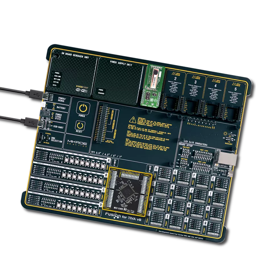
Fusion for Tiva v8
Compiler
NECTO Studio
MCU
TM4C129ENCPDT
With a focus on well-being, our CO2 monitoring solution ensures that indoor spaces maintain optimal CO2 levels, contributing to comfort and cognitive performance
A
A
Hardware Overview
How does it work?
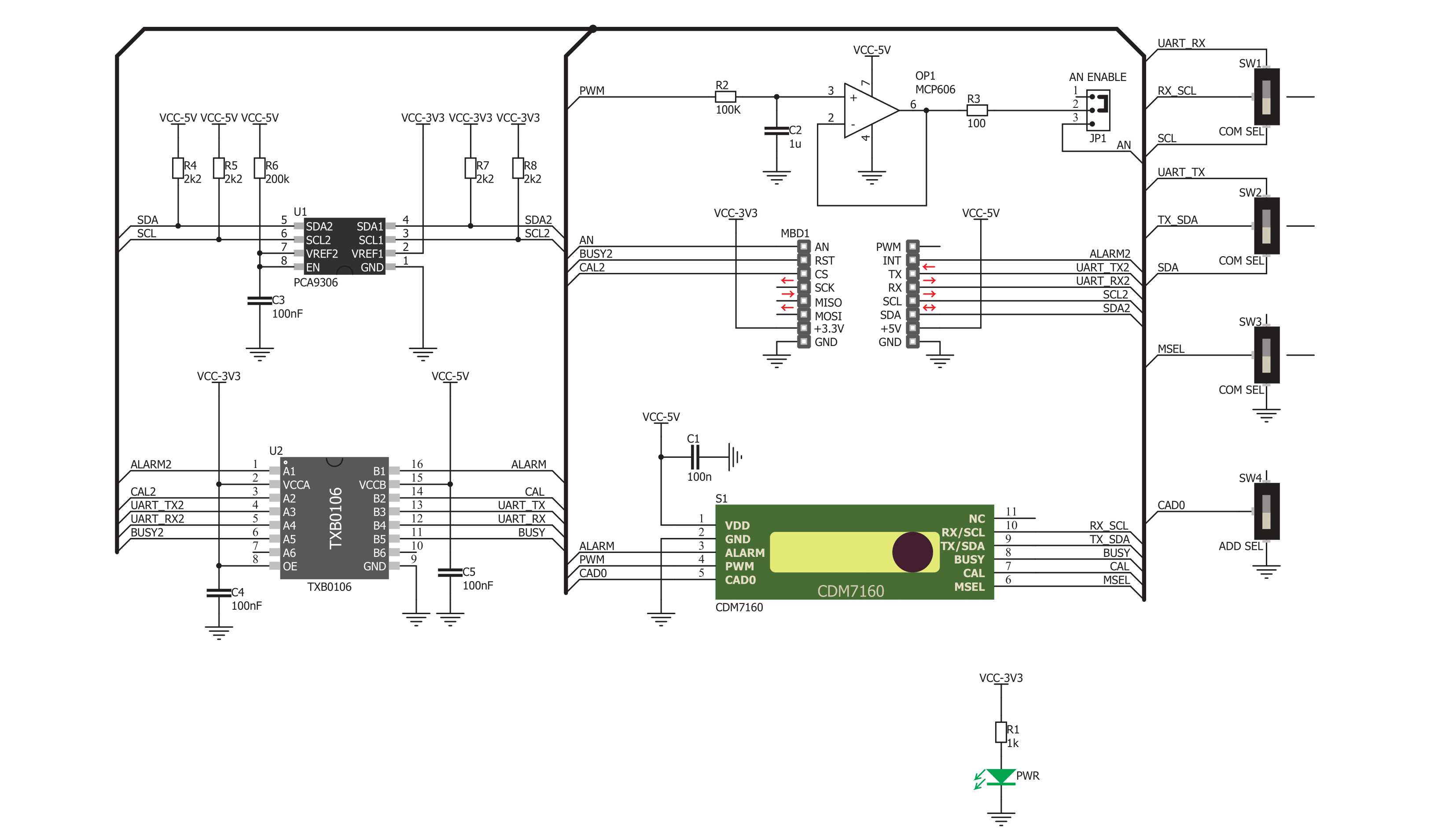
NDIR CO2 Click is based on the CDM7160, a pre-calibrated single light source, dual wavelength, CO2 sensing system from Figaro Engineering. Its light source emits the light, which two IR sensors detect. One light sensor is placed behind the filter, which allows only a part of the IR spectrum affected by the CO2 gas to pass through, while the second sensor is placed behind the filter, which passes the IR spectrum of the light unaffected by the CO2 gas. This forms a differential input for the sensor - an integrated MCU will process the received data by differentiating these readings. This allows the absolute value of the CO2 gas concentration to be obtained and removes any influences of particles and other disturbances, as they affect both sensors equally. This allows consistent readings over various temperatures in various environments, including areas rich with corrosive gases (SO2, H2S, and more), and over a longer period (aging). The CDM7160 sensor can output data in two ways: depending on the status of the MSEL pin, it can use either a UART or I2C communication interface. If this pin is pulled to a LOW logic level, the I2C interface will be selected after the CDM7160 reset cycle. Otherwise, the UART interface will be selected. Since the communication pins are shared between the interfaces (SCL/RX and SDA/TX), they need to be switched to the corresponding pins of the mikroBUS™ whenever a different type of communication is used. Therefore, the Click board™ has a section with three small SMD slide switches labeled COM SEL. Positioning all three switches to the LEFT position will select the I2C interface, while the RIGHT position will select the UART interface. When the I2C interface is
selected, an additional pin is available to set up the I2C address of the device. This pin determines the LSB of the I2C slave address, and when it is pulled to a LOW logic level, this bit becomes 0. This allows up to 2 different devices to be connected to the same I2C bus. This pin is routed to another SMD slide switch labeled the ADD SEL. It is possible to perform two types of calibration for this sensor: zero calibration and background calibration. The zero calibration is performed in the atmosphere with a CO2 concentration of 0 ppm, while the background calibration is performed in the atmosphere with a nominal CO2 value (400 ppm). Since the sensor is influenced by the sea level and the atmospheric pressure, these calibrations should be performed whenever these conditions are changed. This will allow an increased accuracy of the CO2 concentration readings. The CDM7160 sensor offers a pin labeled as CAL for easy calibration: if the CAL pin is pulled to a LOW logic level for about 2 to 11 seconds, a background calibration will be performed. The zero calibration will be performed if pulled to a LOW logic level for more than 12 seconds. This pin should remain HIGH during normal operation. An internal pull-up resistor ensures the pin is always HIGH if it remains floating. This pin is routed to the mikroBUS™ CS pin, labeled as CAL. The ALERT pin of the CDM7160 sensor triggers an interrupt on the host MCU. It will default trigger an interrupt if the CO2 concentration exceeds 1000ppm. The interrupt will be cleared if the concentration drops below 900ppm. These settings can be changed by writing values to the corresponding ALHI and ALLO registers (upper and lower threshold registers). The ALERT pin of the CDM7160 sensor is
routed to the mikroBUS™ INT pin. The BUSY pin of the sensor provides a means to save the sensor from polling sensor registers to verify if the device is ready for communication. By setting an interrupt for the BUSY pin, the MCU can be automatically triggered only when the sensor is ready to accept a new command. A logic LOW level signals the MCU that the sensor cannot accept a new command. The sensor might be unavailable for about 0.3 seconds while internally processing the data. This pin is routed to the mikroBUS™ RST pin, labeled as BSY on the Click board™. Besides UART and I2C communication, the sensor offers a 1KHz PWM signal with the duty cycle, which depends on the CO2 concentration (0 to 5000 ppm of CO2). The Click board™ is equipped with an operational amplifier, which averages the PWM signal, offering analog DC voltage (0 to 5V) on its output, directly proportional to the pulse width of the PWM signal. By switching the SMD jumper labeled as AN ENABLE to EN position, the voltage at the output of this operational amplifier becomes available at the AN pin of the mikroBUS™. By default, the jumper is soldered to the DIS position. The full-scale voltage on the operational amplifier output is 5V (5000 ppm of CO2 equals 5V). To allow communication with 3.3V MCUs, two additional ICs are used: one is the PCA9306, which translates voltage levels of the I2C signals, while the second IC is the TXB0106, used to translate voltage levels of the remaining IC pins, including the UART. These ICs are used on many other designs and have proven reliable solutions.


Features overview
Development board
Fusion for TIVA v8 is a development board specially designed for the needs of rapid development of embedded applications. It supports a wide range of microcontrollers, such as different 32-bit ARM® Cortex®-M based MCUs from Texas Instruments, regardless of their number of pins, and a broad set of unique functions, such as the first-ever embedded debugger/programmer over a WiFi network. The development board is well organized and designed so that the end-user has all the necessary elements, such as switches, buttons, indicators, connectors, and others, in one place. Thanks to innovative manufacturing technology, Fusion for TIVA v8 provides a fluid and immersive working experience, allowing access
anywhere and under any circumstances at any time. Each part of the Fusion for TIVA v8 development board contains the components necessary for the most efficient operation of the same board. An advanced integrated CODEGRIP programmer/debugger module offers many valuable programming/debugging options, including support for JTAG, SWD, and SWO Trace (Single Wire Output)), and seamless integration with the Mikroe software environment. Besides, it also includes a clean and regulated power supply module for the development board. It can use a wide range of external power sources, including a battery, an external 12V power supply, and a power source via the USB Type-C (USB-C) connector.
Communication options such as USB-UART, USB HOST/DEVICE, CAN (on the MCU card, if supported), and Ethernet is also included. In addition, it also has the well-established mikroBUS™ standard, a standardized socket for the MCU card (SiBRAIN standard), and two display options for the TFT board line of products and character-based LCD. Fusion for TIVA v8 is an integral part of the Mikroe ecosystem for rapid development. Natively supported by Mikroe software tools, it covers many aspects of prototyping and development thanks to a considerable number of different Click boards™ (over a thousand boards), the number of which is growing every day.

Microcontroller Overview
MCU Card / MCU

Type
8th Generation
Architecture
ARM Cortex-M4
MCU Memory (KB)
1024
Silicon Vendor
Texas Instruments
Pin count
128
RAM (Bytes)
262144
Used MCU Pins
mikroBUS™ mapper
Take a closer look
Click board™ Schematic
Step by step
Project assembly

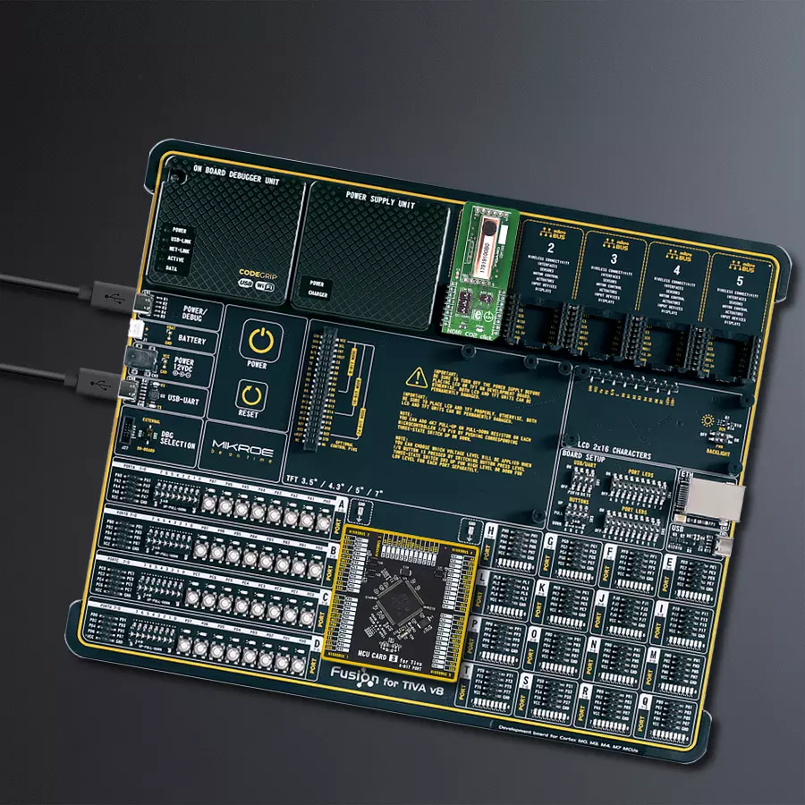
Start by selecting your development board and Click board™. Begin with the Fusion for Tiva v8 as your development board.


Software Support
Library Description
This library contains API for NDIR CO2 Click driver.
Key functions:
ndirco2_read_co2- CO2 Concentration Read functionndirco2_check_average_complete- Average Complete Check functionndirco2_set_mode- Mode Set function
Open Source
Code example
The complete application code and a ready-to-use project are available through the NECTO Studio Package Manager for direct installation in the NECTO Studio. The application code can also be found on the MIKROE GitHub account.
/*!
 * \file
 * \brief NDIRCO2 Click example
 *
 * # Description
 * This application measures absolute CO2 concetration.
 *
 * The demo application is composed of two sections :
 *
 * ## Application Init
 * Initializes I2C driver and performs driver reset and determines
 * number of averaging measurements.
 *
 * ## Application Task
 * Reads CO2 concentration data in ppm unit after each completed measurement.
 * One measurement is finished after 300 ms, and period between two measurements is 2 seconds.
 * Results of measurements logs on USBUART.
 *
 *
 * \author MikroE Team
 *
 */
// ------------------------------------------------------------------- INCLUDES

#include "board.h"
#include "log.h"
#include "ndirco2.h"

// ------------------------------------------------------------------ VARIABLES

static ndirco2_t ndirco2;
static log_t logger;

// ------------------------------------------------------ APPLICATION FUNCTIONS

void application_init ( void )
{
    log_cfg_t log_cfg;
    ndirco2_cfg_t cfg;

    /**
     * Logger initialization.
     * Default baud rate: 115200
     * Default log level: LOG_LEVEL_DEBUG
     * @note If USB_UART_RX and USB_UART_TX
     * are defined as HAL_PIN_NC, you will
     * need to define them manually for log to work.
     * See @b LOG_MAP_USB_UART macro definition for detailed explanation.
     */
    LOG_MAP_USB_UART( log_cfg );
    log_init( &logger, &log_cfg );
    log_info( &logger, "---- Application Init ----" );

    //  Click initialization.

    ndirco2_cfg_setup( &cfg );
    NDIRCO2_MAP_MIKROBUS( cfg, MIKROBUS_1 );
    ndirco2_init( &ndirco2, &cfg );

    Delay_ms ( 300 );

    ndirco2_reset( &ndirco2 );
    ndirco2_write_register( &ndirco2, NDIRCO2_AVERAGING_COUNT_REG, 0x03 );
    ndirco2_set_mode( &ndirco2, NDIRCO2_CONTINUOUS_OP_MODE );
    log_printf( &logger, "NDIR CO2 is initialized \r\n" );
    Delay_ms ( 200 );
}

void application_task ( )
{
    uint16_t co2_data;

    ndirco2_read_co2( &ndirco2, NDIRCO2_CHECK_EACH_MEASURE, &co2_data );
    log_printf( &logger, "CO2 concentration is: %d ppm \r\n", co2_data );
    Delay_ms ( 1000 );
}

int main ( void )
{
    /* Do not remove this line or clock might not be set correctly. */
    #ifdef PREINIT_SUPPORTED
    preinit();
    #endif

    application_init( );

    for ( ; ; )
    {
        application_task( );
    }

    return 0;
}


// ------------------------------------------------------------------------ END


