Master time management with DS1307 and STM32F302VC
Keep track of time in various electronic applications

Published Jul 22, 2025
Click board™
RTC 2 Click
Dev. board
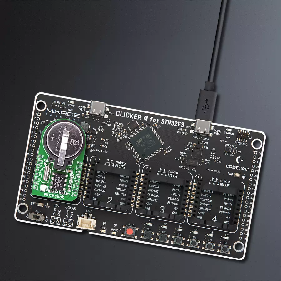
CLICKER 4 for STM32F302VCT6
Compiler
NECTO Studio
MCU
STM32F302VC
Compact time-tracking solution that maintains accurate time records, suitable for applications like IoT, wearables, data logging, and industrial devices
A
A
Hardware Overview
How does it work?
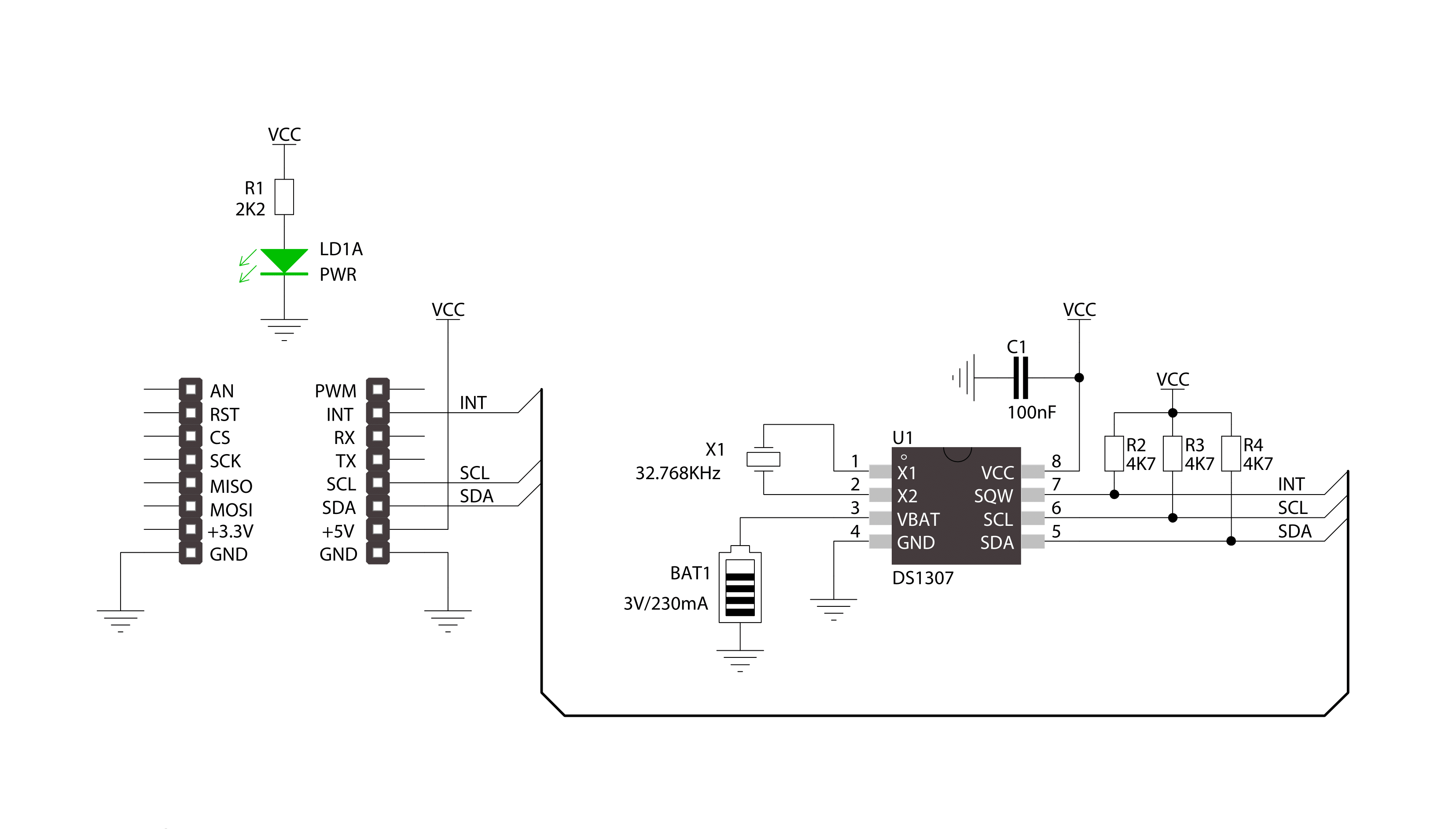
RTC 2 Click is based on the DS1307, a 64x8 serial I2C Real-Time clock from Analog Devices. It is a low-power, full binary-coded decimal (BCD) clock/calendar with 56 bytes of NV SRAM. The end of months is automatically adjusted for months with fewer than 31 days, including corrections for the leap year. The clock can operate in either a 24-hour or 12-hour format with an AM/PM indicator. The RTC has a built-in power-sense circuit that automatically switches to the backup power
supply when it detects a power failure. The RTC 2 comes equipped with a 3V/230mA lithium battery, ensuring timekeeping continues even when the main power supply goes OFF. The RTC 2 Click uses an I2C 2-Wire interface for communication with the host MCU, with a clock rate of up to 400kHz. The interrupt INT pin of this Click board™ outputs one of four square-wave frequencies (1Hz, 4kHz, 8kHz, and 32kHz). When enabled, it outputs frequency depending on values set in configuration
bits. This Click board™ can be operated only with a 5V logic voltage level. The board must perform appropriate logic voltage level conversion before using MCUs with different logic levels. Also, this Click board™ comes equipped with a library containing easy-to-use functions and an example code that can be used as a reference for further development.

Features overview
Development board
Clicker 4 for STM32F3 is a compact development board designed as a complete solution, you can use it to quickly build your own gadgets with unique functionalities. Featuring a STM32F302VCT6, four mikroBUS™ sockets for Click boards™ connectivity, power managment, and more, it represents a perfect solution for the rapid development of many different types of applications. At its core, there is a STM32F302VCT6 MCU, a powerful microcontroller by STMicroelectronics, based on the high-
performance Arm® Cortex®-M4 32-bit processor core operating at up to 168 MHz frequency. It provides sufficient processing power for the most demanding tasks, allowing Clicker 4 to adapt to any specific application requirements. Besides two 1x20 pin headers, four improved mikroBUS™ sockets represent the most distinctive connectivity feature, allowing access to a huge base of Click boards™, growing on a daily basis. Each section of Clicker 4 is clearly marked, offering an intuitive and clean interface. This makes working with the development
board much simpler and thus, faster. The usability of Clicker 4 doesn’t end with its ability to accelerate the prototyping and application development stages: it is designed as a complete solution which can be implemented directly into any project, with no additional hardware modifications required. Four mounting holes [4.2mm/0.165”] at all four corners allow simple installation by using mounting screws. For most applications, a nice stylish casing is all that is needed to turn the Clicker 4 development board into a fully functional, custom design.

Microcontroller Overview
MCU Card / MCU

Architecture
ARM Cortex-M4
MCU Memory (KB)
256
Silicon Vendor
STMicroelectronics
Pin count
100
RAM (Bytes)
40960
Used MCU Pins
mikroBUS™ mapper
Take a closer look
Click board™ Schematic
Step by step
Project assembly

Start by selecting your development board and Click board™. Begin with the CLICKER 4 for STM32F302VCT6 as your development board.


Software Support
Library Description
This library contains API for RTC 2 Click driver.
Key functions:
rtc2_read_byte- Generic read byte of data functionrtc2_write_byte- Generic write byte of data functionrtc2_enable_counting- Enable counting function
Open Source
Code example
The complete application code and a ready-to-use project are available through the NECTO Studio Package Manager for direct installation in the NECTO Studio. The application code can also be found on the MIKROE GitHub account.
/*!
 * \file
 * \brief Rtc6 Click example
 *
 * # Description
 * This application enables usage of Real-TIme clock and calendar with alarm on RTC 6 Click.
 *
 * The demo application is composed of two sections :
 *
 * ## Application Init
 * Initializes driver init, sets time zone, sets UTC-GMT time and alarm time
 *
 * ## Application Task
 * Reads GMT time and Local time. Checks if the alarm is activated.
 * If the alarm is active, it disable alarm and adjusts the new one within 20 seconds.
 * Logs this data on USBUART every 900ms.
 *
 *
 * \author MikroE Team
 *
 */
// ------------------------------------------------------------------- INCLUDES

#include "board.h"
#include "log.h"
#include "rtc6.h"

// ------------------------------------------------------------------ VARIABLES

static rtc6_t rtc6;
static log_t logger;
static rtc6_time_t utc_time;
static rtc6_time_t alarm_time;
static rtc6_time_t local_time;

// ------------------------------------------------------ APPLICATION FUNCTIONS

void application_init ( void )
{
    log_cfg_t log_cfg;
    rtc6_cfg_t cfg;
    int8_t time_zone = 2;

    /**
     * Logger initialization.
     * Default baud rate: 115200
     * Default log level: LOG_LEVEL_DEBUG
     * @note If USB_UART_RX and USB_UART_TX
     * are defined as HAL_PIN_NC, you will
     * need to define them manually for log to work.
     * See @b LOG_MAP_USB_UART macro definition for detailed explanation.
     */
    LOG_MAP_USB_UART( log_cfg );
    log_init( &logger, &log_cfg );
    log_info( &logger, "---- Application Init ----" );

    //  Click initialization.

    rtc6_cfg_setup( &cfg );
    RTC6_MAP_MIKROBUS( cfg, MIKROBUS_1 );
    rtc6_init( &rtc6, &cfg );

    // Set UTC time

    utc_time.seconds  = 40;
    utc_time.minutes  = 59;
    utc_time.hours    = 23;
    utc_time.monthday = 14;
    utc_time.month    = 12;
    utc_time.year     = 18;

    // Set alarm time

    alarm_time.seconds  = 0;
    alarm_time.minutes  = 0;
    alarm_time.hours    = 0;
    alarm_time.weekdays  = 0;
    alarm_time.monthday = 15;
    alarm_time.month    = 12;
    alarm_time.year     = 18;

    rtc6_default_cfg( &rtc6, time_zone, &utc_time, &alarm_time );
    log_info( &logger, " ----- Init successfully ----- " );
    Delay_ms ( 1000 );
    Delay_ms ( 1000 );
}

void application_task ( void )
{
    //  Task implementation.

    rtc6_get_gmt_time( &rtc6, &utc_time );
    rtc6_get_local_time( &rtc6, &local_time );

    log_printf( &logger, "--- UTC time ---\r\nTime : %u %u %u\r\n", ( uint16_t )utc_time.hours, ( uint16_t )utc_time.minutes, ( uint16_t )utc_time.seconds );

    log_printf( &logger, "Date : %u %u %u\r\n", ( uint16_t )utc_time.monthday, ( uint16_t )utc_time.month, utc_time.year );

    log_printf( &logger, "--- Local time ---\r\nTime : %u %u %u\r\n", ( uint16_t )local_time.hours, ( uint16_t )local_time.minutes, ( uint16_t )local_time.seconds );

    log_printf( &logger, "Date : %u %u %u\r\n \r\n", ( uint16_t )local_time.monthday, ( uint16_t )local_time.month, local_time.year );

    if ( rtc6_is_active_alarm( &rtc6 ) != 0 )
    {
        log_printf( &logger, " ----- Active alarm ----- \r\n" );
        rtc6_disable_alarm( &rtc6, RTC6_ALARM_0 );
        rtc6_repeat_alarm( &rtc6, RTC6_ALARM_0, 20 );
    }

    Delay_ms ( 900 );
}

int main ( void )
{
    /* Do not remove this line or clock might not be set correctly. */
    #ifdef PREINIT_SUPPORTED
    preinit();
    #endif

    application_init( );

    for ( ; ; )
    {
        application_task( );
    }

    return 0;
}


// ------------------------------------------------------------------------ END
Additional Support
Resources
Category:RTC


