Experience the next level of accuracy and synchronization in your projects with DS2417 and PIC18F24K50
Let's make every millisecond count!

Published Nov 01, 2023
Click board™
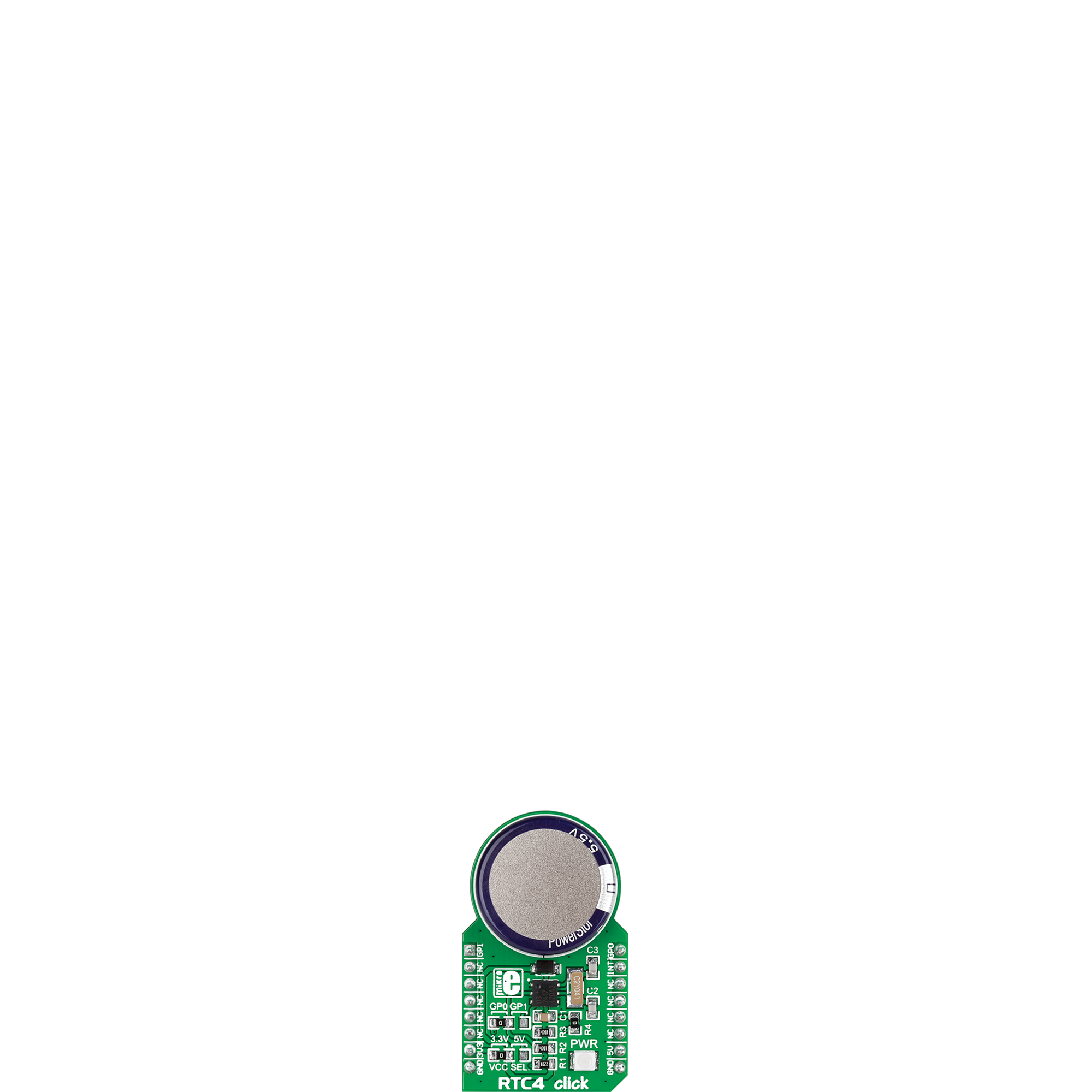
RTC 4 Click
Dev. board
EasyPIC v8
Compiler
NECTO Studio
MCU
PIC18F24K50
Enhance your profitability and efficiency with our real-time clock solution, delivering reliable timekeeping for your critical applications
A
A
Hardware Overview
How does it work?
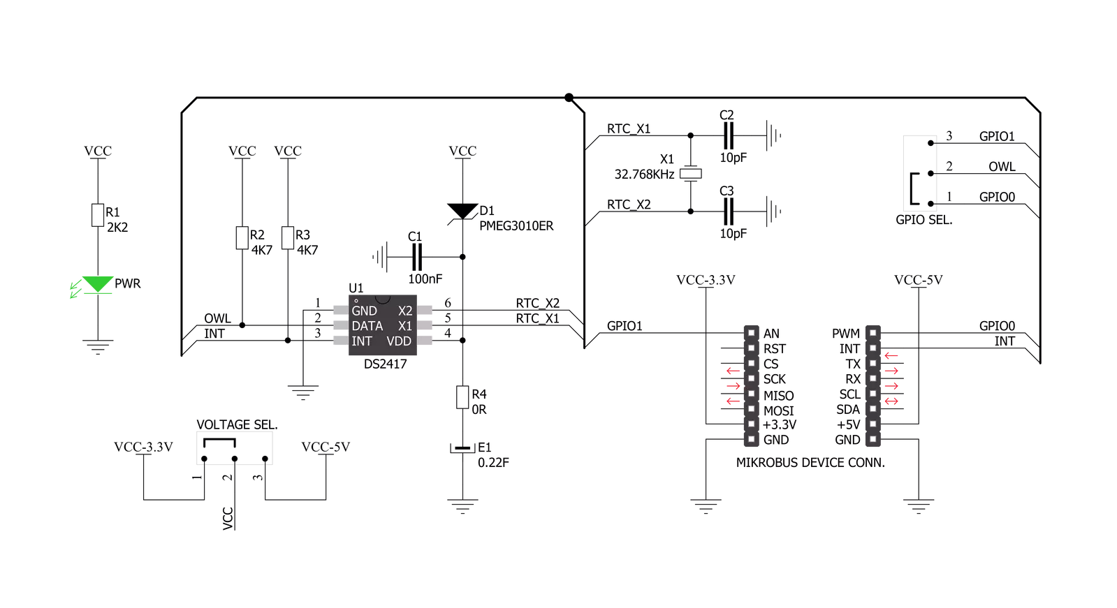
RTC 4 Click is based on the DS2417, a real-time clock from Analog Devices, offering a simple solution for storing and retrieving vital time information with minimal hardware. The DS2417 contains a real-time clock/calendar implemented as a 32-bit binary counter and a unique factory-lasered 64-bit registration number, allowing multiple Click boards™ to be connected on the same data line. It communicates with the host MCU through a standard Dallas Semiconductor 1-Wire interface (16.3kbps). It has a clock accuracy of ±2 minutes per month at a 25 degrees Celsius temperature and a clock frequency derived from an onboard 32.768kHz oscillator. The DS2417's data is nonvolatile and can be used for stand-alone operation thanks to a backup energy source
(an onboard coin cell supercapacitor). The DS2417 adds functions such as a calendar, time and date stamp, and logbook to any electronic device or embedded microcontroller application. It can accumulate 136 years of seconds before rolling over, where time/date is represented by the number of seconds since a reference point, which the user determines. This Click board™ communicates with MCU using the 1-Wire interface that, by definition, requires only one data line (and ground) for communication with MCU. Without the main power supply, the data line can also power the sensor parasitically. The 1-Wire communication line is routed to the GP SEL jumper, allowing the 1-Wire communication signal to the PWM pin or the AN pin of the mikroBUS™
socket. These pins are labeled GP0 and GP1, respectively, the same as the SMD jumper positions, making selecting the desired pin straightforward. Besides, the DS2417 also includes an interrupt feature routed to the INT pin of the mikroBUS™ socket for system output. This Click board™ can operate with either 3.3V or 5V logic voltage levels selected via the VCC SEL jumper. This way, both 3.3V and 5V capable MCUs can use the communication lines properly. Also, this Click board™ comes equipped with a library containing easy-to-use functions and an example code that can be used as a reference for further development.

Features overview
Development board
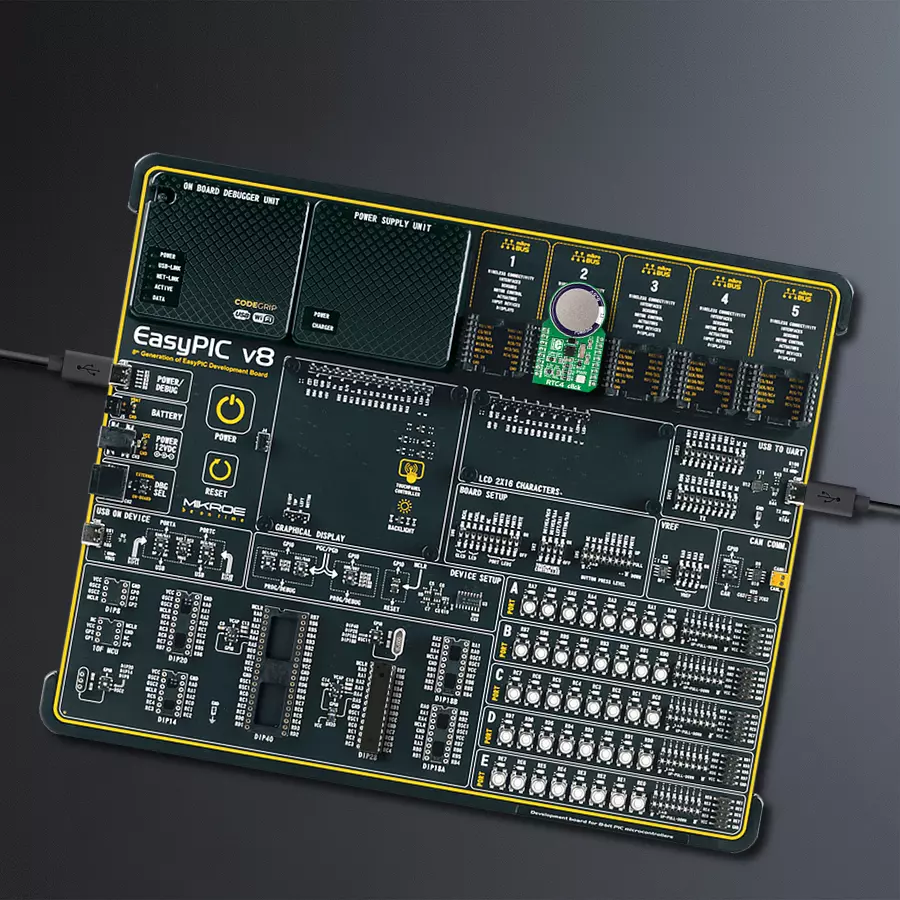
EasyPIC v8 is a development board specially designed for the needs of rapid development of embedded applications. It supports many high pin count 8-bit PIC microcontrollers from Microchip, regardless of their number of pins, and a broad set of unique functions, such as the first-ever embedded debugger/programmer. The development board is well organized and designed so that the end-user has all the necessary elements, such as switches, buttons, indicators, connectors, and others, in one place. Thanks to innovative manufacturing technology, EasyPIC v8 provides a fluid and immersive working experience, allowing access anywhere and under any
circumstances at any time. Each part of the EasyPIC v8 development board contains the components necessary for the most efficient operation of the same board. In addition to the advanced integrated CODEGRIP programmer/debugger module, which offers many valuable programming/debugging options and seamless integration with the Mikroe software environment, the board also includes a clean and regulated power supply module for the development board. It can use a wide range of external power sources, including a battery, an external 12V power supply, and a power source via the USB Type-C (USB-C) connector.
Communication options such as USB-UART, USB DEVICE, and CAN are also included, including the well-established mikroBUS™ standard, two display options (graphical and character-based LCD), and several different DIP sockets. These sockets cover a wide range of 8-bit PIC MCUs, from the smallest PIC MCU devices with only eight up to forty pins. EasyPIC v8 is an integral part of the Mikroe ecosystem for rapid development. Natively supported by Mikroe software tools, it covers many aspects of prototyping and development thanks to a considerable number of different Click boards™ (over a thousand boards), the number of which is growing every day.

Microcontroller Overview
MCU Card / MCU
Architecture
PIC
MCU Memory (KB)
16
Silicon Vendor
Microchip
Pin count
28
RAM (Bytes)
2048
Used MCU Pins
mikroBUS™ mapper
Take a closer look
Click board™ Schematic
Step by step
Project assembly

Start by selecting your development board and Click board™. Begin with the EasyPIC v8 as your development board.


Software Support
Library Description
This library contains API for RTC 4 Click driver.
Key functions:
rtc4_get_interrupt- This function checks the interrupt state of the DS2417 Real time clock/calendar.rtc4_set_date_time- This function sets date and time structure along with interrupt interval.rtc4_get_date_time- This function gets RTC4 time and date structure.
Open Source
Code example
The complete application code and a ready-to-use project are available through the NECTO Studio Package Manager for direct installation in the NECTO Studio. The application code can also be found on the MIKROE GitHub account.
/*!
 * @file main.c
 * @brief RTC 4 Click Example.
 *
 * # Description
 * This example demonstrates the use of the RTC 4 Click board.
 *
 * The demo application is composed of two sections :
 *
 * ## Application Init
 * Initializes the driver and logger and then sets the starting time
 * to 23:59:50 and date to 31.12.2022.
 *
 * ## Application Task
 * With the usage of rtc4_get_date_time we get the time and
 * date from the register and display them on the UART Terminal.
 * The counter increments once per second.
 *
 * @author Aleksandra Cvjetićanin
 *
 */

#include "board.h"
#include "log.h"
#include "rtc4.h"

static rtc4_t rtc4;
static log_t logger;

rtc4_time_t time;
rtc4_date_t date;

void application_init ( void )
{
    log_cfg_t log_cfg;  /**< Logger config object. */
    rtc4_cfg_t rtc4_cfg;  /**< Click config object. */

    /**
     * Logger initialization.
     * Default baud rate: 115200
     * Default log level: LOG_LEVEL_DEBUG
     * @note If USB_UART_RX and USB_UART_TX
     * are defined as HAL_PIN_NC, you will
     * need to define them manually for log to work.
     * See @b LOG_MAP_USB_UART macro definition for detailed explanation.
     */
    LOG_MAP_USB_UART( log_cfg );
    log_init( &logger, &log_cfg );
    log_info( &logger, " Application Init " );

    // Click initialization.
    rtc4_cfg_setup( &rtc4_cfg );
    RTC4_MAP_MIKROBUS( rtc4_cfg, MIKROBUS_1 );
    if ( ONE_WIRE_ERROR == rtc4_init( &rtc4, &rtc4_cfg ) )
    {
        log_error( &logger, " Communication init." );
        for ( ; ; );
    }

    if ( RTC4_ERROR == rtc4_check_communication ( &rtc4 ) )
    {
        log_error( &logger, " Check communication." );
        for ( ; ; );
    }

    time.hours = 23;
    time.min = 59;
    time.sec = 50;

    date.day = 31;
    date.month = 12;
    date.year = 2022;

    rtc4_set_date_time ( &rtc4, &date, &time, RTC4_DCB_INTERVAL_1S );

    log_info( &logger, " Application Task " );
}

void application_task ( void )
{
    while ( rtc4_get_interrupt ( &rtc4 ) );

    if ( RTC4_OK == rtc4_get_date_time ( &rtc4, &date, &time ) )
    {
        log_printf( &logger, "Time: %.2u:%.2u:%.2u\r\n",
                    ( uint16_t ) time.hours, ( uint16_t ) time.min, ( uint16_t ) time.sec );
        log_printf( &logger, "Date: %.2u/%.2u/%u\r\n",
                    ( uint16_t ) date.day, ( uint16_t ) date.month, ( uint16_t ) date.year );
        log_printf( &logger, "------------------------\r\n\n");
    }
}

int main ( void )
{
    /* Do not remove this line or clock might not be set correctly. */
    #ifdef PREINIT_SUPPORTED
    preinit();
    #endif

    application_init( );

    for ( ; ; )
    {
        application_task( );
    }

    return 0;
}

// ------------------------------------------------------------------------ END


