Ensure stable and protected power delivery with HS2950P and STM32L432KC
Load protection HotSwitch® for various load conditions

Published Dec 27, 2023
Click board™
Current Limit 10 Click
Dev Board
Fusion for STM32 v8
Compiler
NECTO Studio
MCU
STM32L432KC
Keep your electronic device safe by controlling the amount of electrical current it uses and protecting it from voltage-related issues
A
A
Hardware Overview
How does it work?
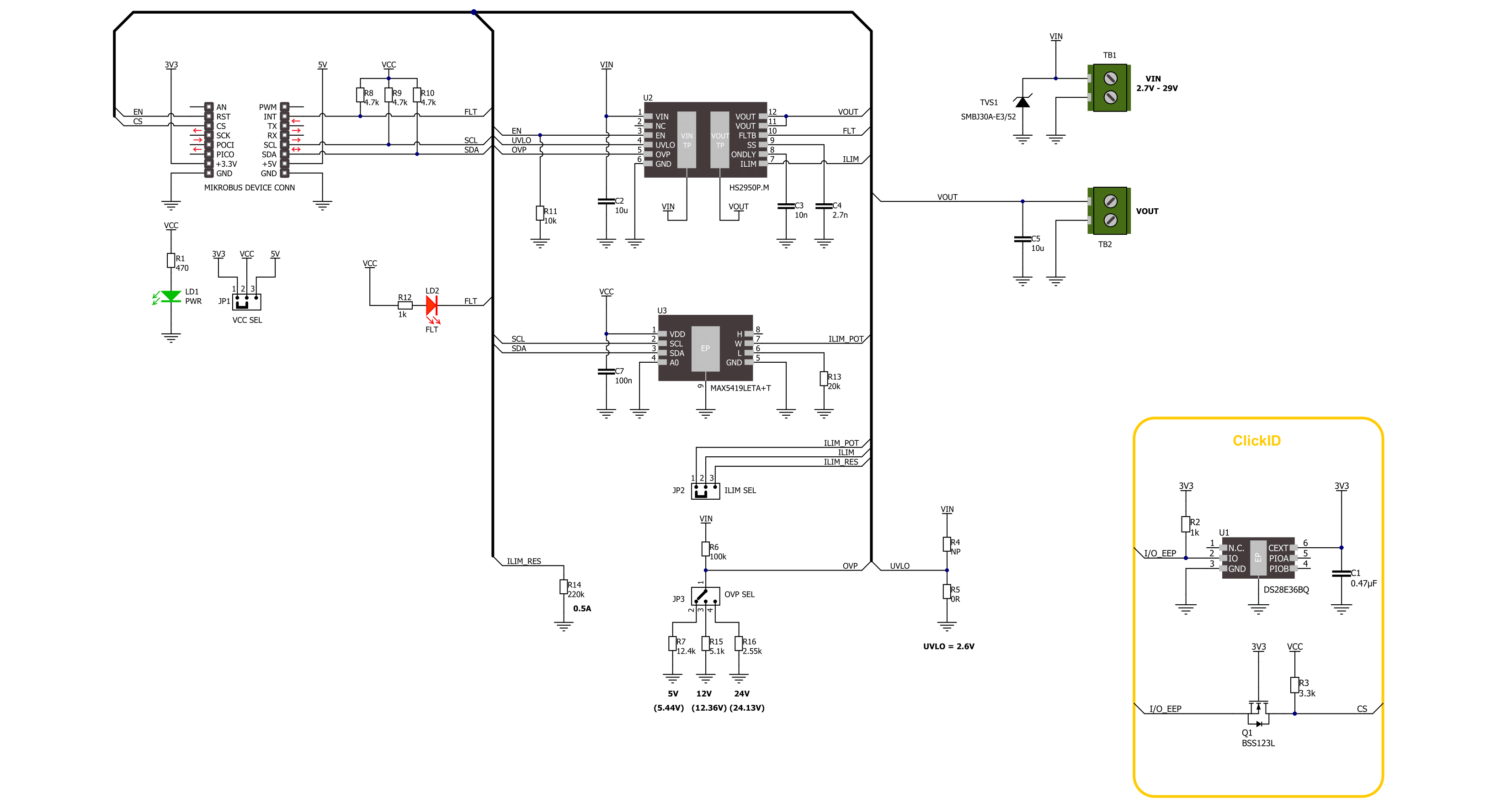
Current Limit 10 Click is based on the HS2950P, a load protection HotSwitch from Semtech. It utilizes flexible and programmable protection features and can handle multiple fault conditions. During fault conditions, automatic output discharge will be activated, thus protecting the load, and the HS2950P will automatically restart from a fault condition. The under-voltage lockout threshold is set to the default position (2.6V). The overvoltage protection can be externally set over the OVP SEL jumper, choosing between values 5.44V, 12.36V,
and 24.13V. The OVP is set by default to 5.44V. The current limit threshold can be set over the MAX5419, a nonvolatile digital potentiometer from Analog Devices. You can also choose the onboard external resistor for a fixed 0.5A value. The selection can be made over the ILIM SEL jumper. The soft start time is set to 0.32 ms, and the turn-on delay is set to 4 ms. Current Limit 10 Click uses a standard 2-wire I2C interface of the MAX5419 to allow the host MCU to set the limit threshold. The HS2950P will alert the host MCU when the fault
condition occurs over the FLT pin, along with the FLT LED indicator. Finally, you can turn off the current limiter over the enable EN pin. This Click board™ can operate with either 3.3V or 5V logic voltage levels selected via the VCC SEL jumper. This way, both 3.3V and 5V capable MCUs can use the communication lines properly. Also, this Click board™ comes equipped with a library containing easy-to-use functions and an example code that can be used as a reference for further development.

Features overview
Development board
Fusion for STM32 v8 is a development board specially designed for the needs of rapid development of embedded applications. It supports a wide range of microcontrollers, such as different 32-bit ARM® Cortex®-M based MCUs from STMicroelectronics, regardless of their number of pins, and a broad set of unique functions, such as the first-ever embedded debugger/programmer over WiFi. The development board is well organized and designed so that the end-user has all the necessary elements, such as switches, buttons, indicators, connectors, and others, in one place. Thanks to innovative manufacturing technology, Fusion for STM32 v8 provides a fluid and immersive working experience, allowing
access anywhere and under any circumstances at any time. Each part of the Fusion for STM32 v8 development board contains the components necessary for the most efficient operation of the same board. An advanced integrated CODEGRIP programmer/debugger module offers many valuable programming/debugging options, including support for JTAG, SWD, and SWO Trace (Single Wire Output)), and seamless integration with the Mikroe software environment. Besides, it also includes a clean and regulated power supply module for the development board. It can use a wide range of external power sources, including a battery, an external 12V power supply, and a power source via the USB Type-C (USB-C) connector.
Communication options such as USB-UART, USB HOST/DEVICE, CAN (on the MCU card, if supported), and Ethernet is also included. In addition, it also has the well-established mikroBUS™ standard, a standardized socket for the MCU card (SiBRAIN standard), and two display options for the TFT board line of products and character-based LCD. Fusion for STM32 v8 is an integral part of the Mikroe ecosystem for rapid development. Natively supported by Mikroe software tools, it covers many aspects of prototyping and development thanks to a considerable number of different Click boards™ (over a thousand boards), the number of which is growing every day.

Microcontroller Overview
MCU Card / MCU

Type
8th Generation
Architecture
ARM Cortex-M4
MCU Memory (KB)
256
Silicon Vendor
STMicroelectronics
Pin count
32
RAM (Bytes)
65536
Used MCU Pins
mikroBUS™ mapper
Take a closer look
Schematic
Step by step
Project assembly

Start by selecting your development board and Click board™. Begin with the Fusion for STM32 v8 as your development board.


Track your results in real time
Application Output
After pressing the "FLASH" button on the left-side panel, it is necessary to open the UART terminal to display the achieved results. By clicking on the Tools icon in the right-hand panel, multiple different functions are displayed, among which is the UART Terminal. Click on the offered "UART Terminal" icon.

Once the UART terminal is opened, the window takes on a new form. At the top of the tab are two buttons, one for adjusting the parameters of the UART terminal and the other for connecting the UART terminal. The tab's lower part is reserved for displaying the achieved results. Before connecting, the terminal has a Disconnected status, indicating that the terminal is not yet active. Before connecting, it is necessary to check the set parameters of the UART terminal. Click on the "OPTIONS" button.

In the newly opened UART Terminal Options field, we check if the terminal settings are correct, such as the set port and the Baud rate of UART communication. If the data is not displayed properly, it is possible that the Baud rate value is not set correctly and needs to be adjusted to 115200. If all the parameters are set correctly, click on "CONFIGURE".

The next step is to click on the "CONNECT" button, after which the terminal status changes from Disconnected to Connected in green, and the data is displayed in the Received data field.

Software Support
Library Description
This library contains API for Current Limit 10 Click driver.
Key functions:
currentlimit10_set_limit- This function sets the desired current limit threshold using the I2C serial interface.currentlimit10_get_fault- This function gets the state of the fault flag to indicate overcurrent, overtemperature, or reverse-voltage conditions.currentlimit10_enable- This function turns on the power switch and enables the internal MOSFET.
Open Source
Code example
This example can be found in NECTO Studio. Feel free to download the code, or you can copy the code below.
/*!
* @file main.c
* @brief Current Limit 10 Click example
*
* # Description
* This library contains API for the Current Limit 10 Click driver for the current limiting
* to a certain value and displays the sources a current proportional to the load current [A].
*
* The demo application is composed of two sections :
*
* ## Application Init
* Initialization of I2C module and log UART.
* After driver initialization, the app executes a default configuration.
*
* ## Application Task
* This example demonstrates the use of the Current Limit 10 Click board.
* The demo application sets the current limit threshold of 750 mA and
* checks the fault flag for overcurrent conditions.
*
* @author Nenad Filipovic
*
*/
#include "board.h"
#include "log.h"
#include "currentlimit10.h"
static currentlimit10_t currentlimit10;
static log_t logger;
void application_init ( void )
{
log_cfg_t log_cfg; /**< Logger config object. */
currentlimit10_cfg_t currentlimit10_cfg; /**< Click config object. */
/**
* Logger initialization.
* Default baud rate: 115200
* Default log level: LOG_LEVEL_DEBUG
* @note If USB_UART_RX and USB_UART_TX
* are defined as HAL_PIN_NC, you will
* need to define them manually for log to work.
* See @b LOG_MAP_USB_UART macro definition for detailed explanation.
*/
LOG_MAP_USB_UART( log_cfg );
log_init( &logger, &log_cfg );
log_info( &logger, " Application Init " );
// Click initialization.
currentlimit10_cfg_setup( ¤tlimit10_cfg );
CURRENTLIMIT10_MAP_MIKROBUS( currentlimit10_cfg, MIKROBUS_1 );
if ( I2C_MASTER_ERROR == currentlimit10_init( ¤tlimit10, ¤tlimit10_cfg ) )
{
log_error( &logger, " Communication init." );
for ( ; ; );
}
if ( CURRENTLIMIT10_ERROR == currentlimit10_default_cfg ( ¤tlimit10 ) )
{
log_error( &logger, " Default configuration." );
for ( ; ; );
}
log_info( &logger, " Application Task " );
Delay_ms( 100 );
}
void application_task ( void )
{
if ( CURRENTLIMIT10_OK == currentlimit10_set_limit( ¤tlimit10, 0.75 ) )
{
Delay_ms( 100 );
if ( CURRENTLIMIT10_FAULT_FLAG == currentlimit10_get_fault( ¤tlimit10 ) )
{
log_printf( &logger, "Fault flag: Overcurrent\r\n" );
Delay_ms( 100 );
}
else
{
log_printf( &logger, " Current limit is 0.75 A\r\n" );
Delay_ms( 100 );
}
}
Delay_ms( 1000 );
}
void main ( void )
{
application_init( );
for ( ; ; )
{
application_task( );
}
}
// ------------------------------------------------------------------------ END


