Simplify pressure monitoring with HSPPAD042A and TM4C129ENCPDT
Sensing the unseen: Navigating pressure with digital precision
Published Oct 13, 2023
Click board™
Pressure 10 Click
Dev. board
Fusion for Tiva v8
Compiler
NECTO Studio
MCU
TM4C129ENCPDT
Our digital pressure sensors are at the forefront of measurement technology, offering unparalleled accuracy for critical applications, from industrial processes to scientific research
A
A
Hardware Overview
How does it work?
Pressure 10 Click is based on the HSPPAD042A, a digital pressure sensor from ALPS Alpine. This sensor consists of a piezoresistive pressure sensing element and a mixed-signal ASIC which performs A/D conversions and provides the conversion results through a digital interface. MEMS technology, which this sensor element is made of, offers a high sensing precision with ±0.7hPa absolute and ±0.05hPa relative pressure accuracy and industry-lowest current consumption of 1.8μA in low power mode. The sensor is enclosed in a small LGA package and can operate in a range of 300 hPa to 1100 hPa but can withstand up to 30,000 hPa before the membrane breaks down. The HSPPAD042A offers a set of pressure and temperature measurement options. Several measurement modes can be set by CTL1.MODE
bit in 0x0F register. After software reset command is detected, the digital regulator is disabled and all register values are reset and measurement mode is set to Register Action Mode. FIFO buffer allows for an optimization of the host firmware, reducing the data traffic through the communication interface. The interrupt is available over the RDY pin (Data Ready pin), and can be used to indicates measurement completion. Multiple flags can be set to the RDY pin. They are all OR output and the change will be effective immediately even during the measurement. Pressure 10 Click offers a choice between two interfaces: I2C and SPI. The selection can be done by positioning SMD jumpers labeled as COMM SEL to an appropriate position. Note that all the jumpers must be placed to the same side, or else the Click board™ may become
unresponsive. While the I2C interface is selected, the HSPPAD042A allows the choice of the least significant bit (LSB) of its I2C slave address. This can be done by using the SMD jumper labeled as ADDR SEL. This Click Board™ uses both I2C and SPI communication interfaces. It is designed to be operated only with 3.3V logic levels. A proper logic voltage level conversion should be performed before the Click board™ is used with MCUs with logic levels of 5V. More information about the HSPPAD042A can be found in the attached datasheet. However, the Click board™ comes equipped with a library that contains easy to use functions and a usage example that may be used as a reference for the development.


Features overview
Development board
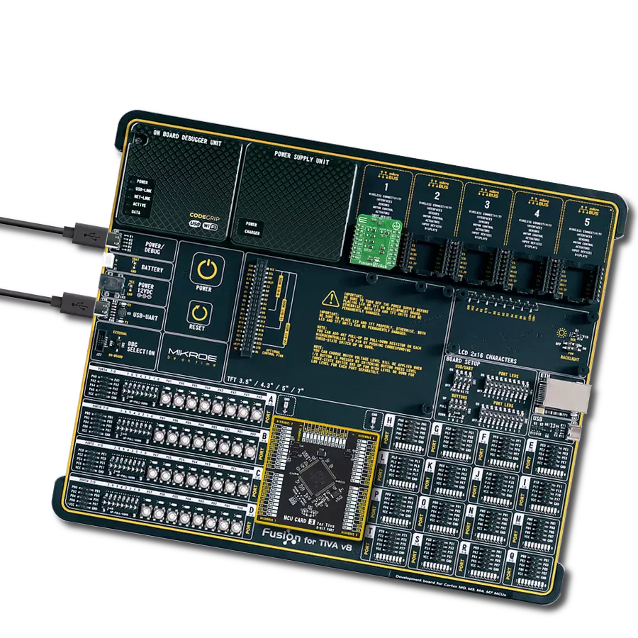
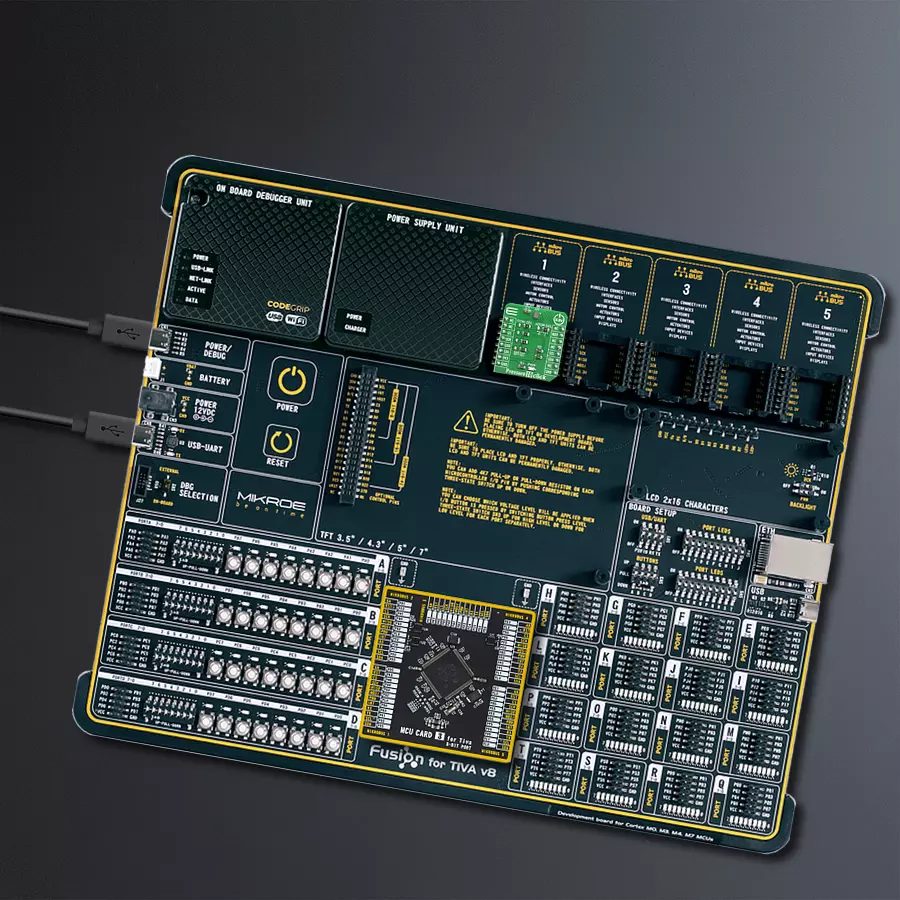
Fusion for TIVA v8 is a development board specially designed for the needs of rapid development of embedded applications. It supports a wide range of microcontrollers, such as different 32-bit ARM® Cortex®-M based MCUs from Texas Instruments, regardless of their number of pins, and a broad set of unique functions, such as the first-ever embedded debugger/programmer over a WiFi network. The development board is well organized and designed so that the end-user has all the necessary elements, such as switches, buttons, indicators, connectors, and others, in one place. Thanks to innovative manufacturing technology, Fusion for TIVA v8 provides a fluid and immersive working experience, allowing access
anywhere and under any circumstances at any time. Each part of the Fusion for TIVA v8 development board contains the components necessary for the most efficient operation of the same board. An advanced integrated CODEGRIP programmer/debugger module offers many valuable programming/debugging options, including support for JTAG, SWD, and SWO Trace (Single Wire Output)), and seamless integration with the Mikroe software environment. Besides, it also includes a clean and regulated power supply module for the development board. It can use a wide range of external power sources, including a battery, an external 12V power supply, and a power source via the USB Type-C (USB-C) connector.
Communication options such as USB-UART, USB HOST/DEVICE, CAN (on the MCU card, if supported), and Ethernet is also included. In addition, it also has the well-established mikroBUS™ standard, a standardized socket for the MCU card (SiBRAIN standard), and two display options for the TFT board line of products and character-based LCD. Fusion for TIVA v8 is an integral part of the Mikroe ecosystem for rapid development. Natively supported by Mikroe software tools, it covers many aspects of prototyping and development thanks to a considerable number of different Click boards™ (over a thousand boards), the number of which is growing every day.

Microcontroller Overview
MCU Card / MCU

Type
8th Generation
Architecture
ARM Cortex-M4
MCU Memory (KB)
1024
Silicon Vendor
Texas Instruments
Pin count
128
RAM (Bytes)
262144
Used MCU Pins
mikroBUS™ mapper
Take a closer look
Click board™ Schematic

Step by step
Project assembly

Start by selecting your development board and Click board™. Begin with the Fusion for Tiva v8 as your development board.


Software Support
Library Description
This library contains API for Pressure 10 Click driver.
Key functions:
pressure10_send_cmd- Send commandpressure10_check_communication- Check communicationpressure10_get_status- Get status function
Open Source
Code example
The complete application code and a ready-to-use project are available through the NECTO Studio Package Manager for direct installation in the NECTO Studio. The application code can also be found on the MIKROE GitHub account.
/*!
 * \file
 * \brief Pressure10 Click example
 *
 * # Description
 * Pressure 10 Click features a digital interface barometric pressure sensor, based on
 * piezoresistive bridge. It can use both SPI and I2C communication protocols, allowing
 * it to be interfaced with a broad range of MCUs.
 *
 * The demo application is composed of two sections :
 *
 * ## Application Init
 * Initializes the driver, checks the communication and configures the module for measurement.
 *
 * ## Application Task
 * Reads the pressure and temperature data every 1500ms and displays the results on the USB UART.
 *
 * \author MikroE Team
 *
 */
// ------------------------------------------------------------------- INCLUDES

#include "board.h"
#include "log.h"
#include "pressure10.h"

// ------------------------------------------------------------------ VARIABLES

static pressure10_t pressure10;
static log_t logger;

static uint8_t check_com;

// ------------------------------------------------------ APPLICATION FUNCTIONS

void application_init ( void )
{
    log_cfg_t log_cfg;
    pressure10_cfg_t cfg;

    /**
     * Logger initialization.
     * Default baud rate: 115200
     * Default log level: LOG_LEVEL_DEBUG
     * @note If USB_UART_RX and USB_UART_TX
     * are defined as HAL_PIN_NC, you will
     * need to define them manually for log to work.
     * See @b LOG_MAP_USB_UART macro definition for detailed explanation.
     */
    LOG_MAP_USB_UART( log_cfg );
    log_init( &logger, &log_cfg );
    log_info( &logger, "---- Application Init ----" );

    //  Click initialization.

    pressure10_cfg_setup( &cfg );
    PRESSURE10_MAP_MIKROBUS( cfg, MIKROBUS_1 );
    pressure10_init( &pressure10, &cfg );

    check_com = pressure10_check_communication( &pressure10 );
    if ( check_com == 0 )
    {
        log_printf( &logger, ">> Communication [OK]\r\n" );
    }
    else
    {
        log_printf( &logger, ">> Communication [ERROR]\r\n" );
        for( ; ; );
    }

    pressure10_default_cfg ( &pressure10 );
    log_printf( &logger, "----------------------------\r\n" );
}

void application_task ( void )
{
    float temperature;
    float pressure;

    pressure = pressure10_get_pressure( &pressure10 );
    temperature = pressure10_get_temperature( &pressure10 );

    log_printf( &logger, ">> Temperature: %.2f C\r\n", temperature );

    log_printf( &logger, "----------------------------\r\n" );

    log_printf( &logger, ">> Pressure: %.2f mBar\r\n", pressure );

    log_printf( &logger, "----------------------------\r\n" );

    Delay_ms ( 1000 );
    Delay_ms ( 500 );
}

int main ( void )
{
    /* Do not remove this line or clock might not be set correctly. */
    #ifdef PREINIT_SUPPORTED
    preinit();
    #endif

    application_init( );

    for ( ; ; )
    {
        application_task( );
    }

    return 0;
}


// ------------------------------------------------------------------------ END
Additional Support
Resources
Category:Pressure


