Experience the vast canvas of possibilities with green LED matrix based on IS31FL3733 and STM32L496AG
Green glow extravaganza
Published Jul 22, 2025
Click board™
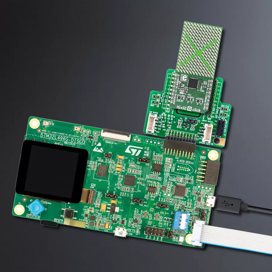
16x12 G Click
Dev. board
Discovery kit with STM32L496AG MCU
Compiler
NECTO Studio
MCU
STM32L496AG
Illuminate your imagination and infuse your projects with eco-friendly brilliance using our 16x12 green LED matrix, where every pixel is an opportunity to craft dynamic, energy-efficient visuals that captivate, inform, and inspire
A
A
Hardware Overview
How does it work?
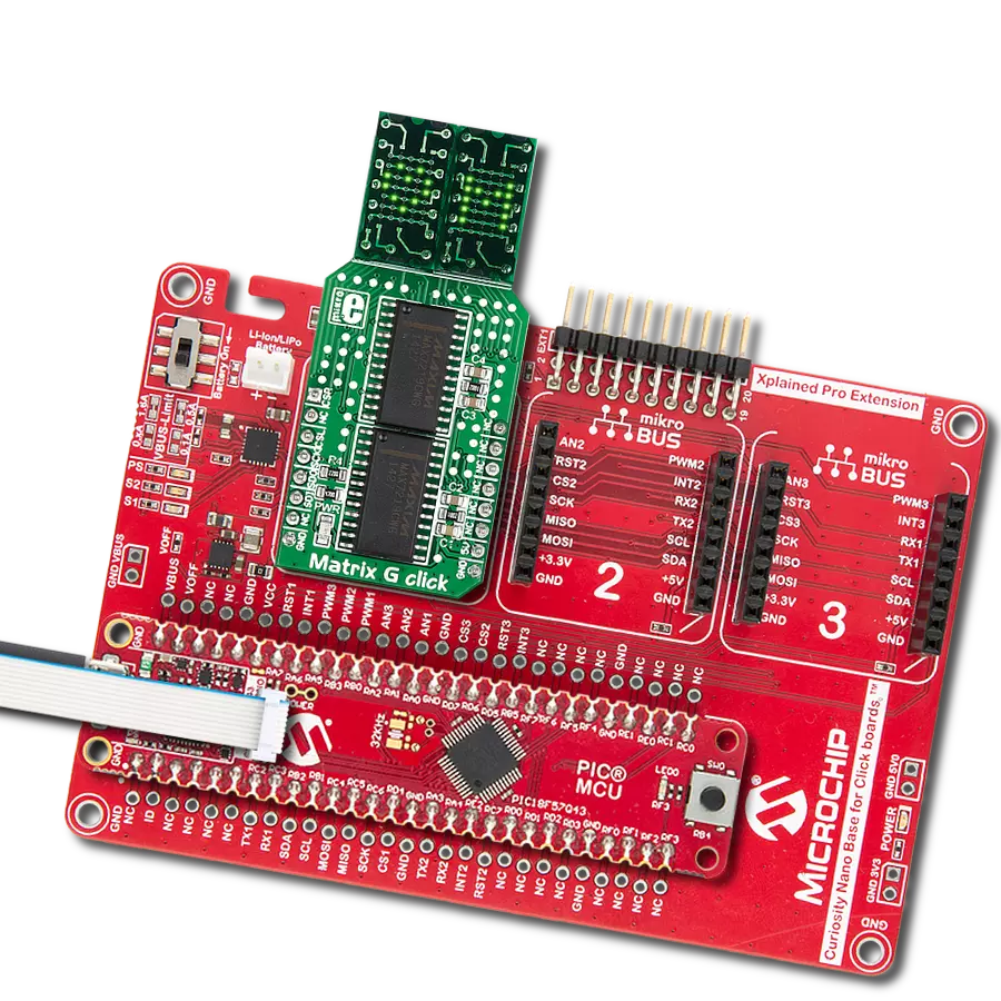
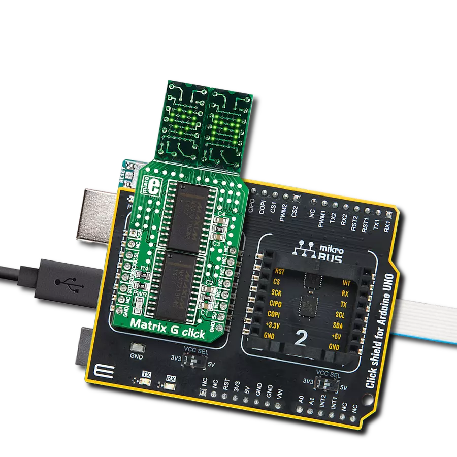
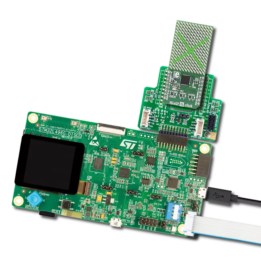
16x12 G Click carries a 16x12 LED display and the IS31FL3733 matrix driver. The click is designed to run on either a 3.3V or 5V power supply. It communicates with the target microcontroller over the I2C interface and the following pins on the mikroBUS™ line: INT, RST, and CS. Each LED can be controlled individually for on/off control
and light intensity. The IS31FL3733 is a general purpose 12×16 LED matrix driver with a 1/12 cycle rate. Each of the 192 LEDs can be dimmed individually with 8-bit PWM data, which allows 256 steps of linear dimming. The driver has selectable 3 Auto Breath Modes for each LED ( ABM-1, ABM-2, and ABM-3). This Click board™ can operate with
either 3.3V or 5V logic voltage levels selected via the VCC SEL jumper. This way, both 3.3V and 5V capable MCUs can use the communication lines properly. Also, this Click board™ comes equipped with a library containing easy-to-use functions and an example code that can be used as a reference for further development.


Features overview
Development board
The 32L496GDISCOVERY Discovery kit serves as a comprehensive demonstration and development platform for the STM32L496AG microcontroller, featuring an Arm® Cortex®-M4 core. Designed for applications that demand a balance of high performance, advanced graphics, and ultra-low power consumption, this kit enables seamless prototyping for a wide range of embedded solutions. With its innovative energy-efficient
architecture, the STM32L496AG integrates extended RAM and the Chrom-ART Accelerator, enhancing graphics performance while maintaining low power consumption. This makes the kit particularly well-suited for applications involving audio processing, graphical user interfaces, and real-time data acquisition, where energy efficiency is a key requirement. For ease of development, the board includes an onboard ST-LINK/V2-1
debugger/programmer, providing a seamless out-of-the-box experience for loading, debugging, and testing applications without requiring additional hardware. The combination of low power features, enhanced memory capabilities, and built-in debugging tools makes the 32L496GDISCOVERY kit an ideal choice for prototyping advanced embedded systems with state-of-the-art energy efficiency.

Microcontroller Overview
MCU Card / MCU

Architecture
ARM Cortex-M4
MCU Memory (KB)
1024
Silicon Vendor
STMicroelectronics
Pin count
169
RAM (Bytes)
327680
Used MCU Pins
mikroBUS™ mapper
Take a closer look
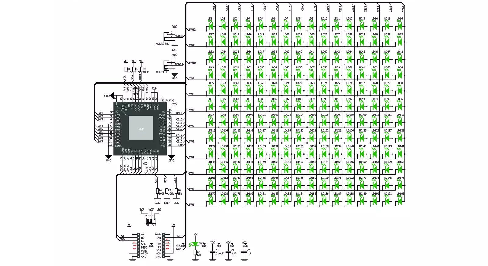
Click board™ Schematic
Step by step
Project assembly

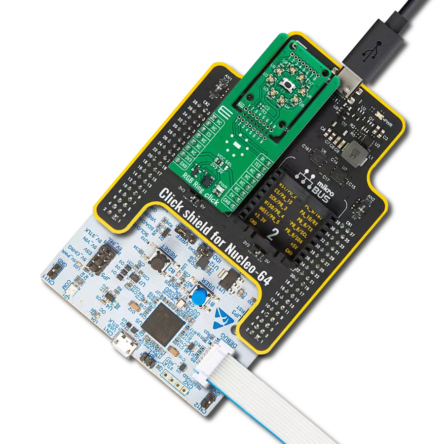
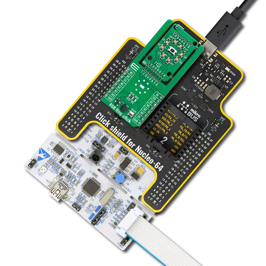
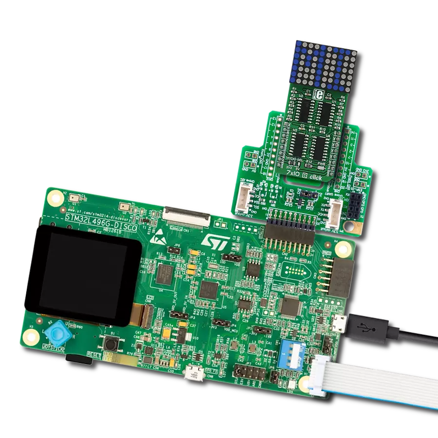
Start by selecting your development board and Click board™. Begin with the Discovery kit with STM32L496AG MCU as your development board.


Track your results in real time
Application Output
1. Application Output - In Debug mode, the 'Application Output' window enables real-time data monitoring, offering direct insight into execution results. Ensure proper data display by configuring the environment correctly using the provided tutorial.

2. UART Terminal - Use the UART Terminal to monitor data transmission via a USB to UART converter, allowing direct communication between the Click board™ and your development system. Configure the baud rate and other serial settings according to your project's requirements to ensure proper functionality. For step-by-step setup instructions, refer to the provided tutorial.

3. Plot Output - The Plot feature offers a powerful way to visualize real-time sensor data, enabling trend analysis, debugging, and comparison of multiple data points. To set it up correctly, follow the provided tutorial, which includes a step-by-step example of using the Plot feature to display Click board™ readings. To use the Plot feature in your code, use the function: plot(*insert_graph_name*, variable_name);. This is a general format, and it is up to the user to replace 'insert_graph_name' with the actual graph name and 'variable_name' with the parameter to be displayed.

Software Support
Library Description
This library contains API for 16x12 G Click driver.
Key functions:
c16x12g_display_image- Display image functionc16x12g_display_byte- Display one byte functionc16x12g_display_text- Display text with scroll function
Open Source
Code example
The complete application code and a ready-to-use project are available through the NECTO Studio Package Manager for direct installation in the NECTO Studio. The application code can also be found on the MIKROE GitHub account.
/*!
 * \file
 * \brief 16x12 Click example
 *
 * # Description
 * This application draw image on the led matrics.
 *
 * The demo application is composed of two sections :
 *
 * ## Application Init
 * Initialization default device configuration, sets LED mode,
 * configuration ABM and display one character.
 *
 * ## Application Task
 * Clear display, display one by one leds, display one character,
 * display image and display text with scroll.
 *
 * \author MikroE Team
 *
 */
// ------------------------------------------------------------------- INCLUDES

#include "board.h"
#include "log.h"
#include "c16x12.h"

// ------------------------------------------------------------------ VARIABLES

static c16x12_t c16x12;
static log_t logger;

static uint8_t scroll_speed = 50;
static c16x12_abm_t abm_1;
static c16x12_abm_t abm_2;


char demo_text[ 7 ] = "MikroE";
uint16_t demo_image_light[ 12 ] =
{ 0x0000, 0x0666, 0x0CCC, 0x1998, 0x3330, 0x6660, 0x3330, 0x1998, 0x0CCC, 0x0666, 0x0000, 0x0000 };
uint16_t demo_image_dark[ 12 ]  =
{ 0xFFFF, 0xF999, 0xF333, 0xE667, 0xCCCF, 0x999F, 0xCCCF, 0xE667, 0xF333, 0xF999, 0xFFFF, 0xFFFF };

char name[] = "16x12";


// ------------------------------------------------------ APPLICATION FUNCTIONS

void application_init ( void )
{
    log_cfg_t log_cfg;
    c16x12_cfg_t cfg;

    /**
     * Logger initialization.
     * Default baud rate: 115200
     * Default log level: LOG_LEVEL_DEBUG
     * @note If USB_UART_RX and USB_UART_TX
     * are defined as HAL_PIN_NC, you will
     * need to define them manually for log to work.
     * See @b LOG_MAP_USB_UART macro definition for detailed explanation.
     */
    LOG_MAP_USB_UART( log_cfg );
    log_init( &logger, &log_cfg );
    log_info( &logger, "---- Application Init ----" );

    //  Click initialization.

    c16x12_cfg_setup( &cfg );
    C16X12_MAP_MIKROBUS( cfg, MIKROBUS_1 );
    c16x12_init( &c16x12, &cfg );

    c16x12g_device_reset( &c16x12 );
    Delay_ms ( 1000 );

    c16x12_default_cfg( &c16x12 );
    c16x12g_set_global_current_control( &c16x12, 255 );
    c16x12g_set_leds_mode( &c16x12, C16X12G_LED_MODE_ABM1 );

    abm_1.time_1     = C16X12G_ABM_T1_840MS;
    abm_1.time_2     = C16X12G_ABM_T2_840MS;
    abm_1.time_3     = C16X12G_ABM_T3_840MS;
    abm_1.time_4     = C16X12G_ABM_T4_840MS;
    abm_1.loop_begin = C16X12G_ABM_LOOP_BEGIN_T1;
    abm_1.loop_end   = C16X12G_ABM_LOOP_END_T3;
    abm_1.loop_times = C16X12G_ABM_LOOP_FOREVER;

    abm_2.time_1     = C16X12G_ABM_T1_210MS;
    abm_2.time_2     = C16X12G_ABM_T2_0MS;
    abm_2.time_3     = C16X12G_ABM_T3_210MS;
    abm_2.time_4     = C16X12G_ABM_T4_0MS;
    abm_2.loop_begin = C16X12G_ABM_LOOP_BEGIN_T1;
    abm_2.loop_end   = C16X12G_ABM_LOOP_END_T3;
    abm_2.loop_times = C16X12G_ABM_LOOP_FOREVER;

    c16x12g_config_abm( &c16x12, C16X12G_ABM_NUM_1, &abm_2 );
    c16x12g_start_abm( &c16x12 );
    c16x12g_display_text( &c16x12, &name[ 0 ], 5, scroll_speed );

    c16x12g_config_abm( &c16x12, C16X12G_ABM_NUM_1, &abm_1 );
    c16x12g_start_abm( &c16x12 );
    c16x12g_display_byte( &c16x12, 'G' );
    Delay_ms ( 1000 );
    Delay_ms ( 1000 );
    Delay_ms ( 1000 );
    Delay_ms ( 1000 );
    Delay_ms ( 1000 );

    c16x12g_config_abm( &c16x12, C16X12G_ABM_NUM_1, &abm_2 );
    c16x12g_start_abm( &c16x12 );
}

void application_task ( void )
{
    uint8_t cnt = 0;

    c16x12g_display_text( &c16x12, &demo_text[ 0 ], 6, scroll_speed );

    c16x12g_clear_display( &c16x12 );

    // Display point
    for ( cnt = 1; cnt <= 12; cnt++ )
    {
        c16x12g_set_led( &c16x12, cnt, cnt, C16X12G_LED_STATE_ON, C16X12G_STOP_SETTINGS );
        Delay_ms ( 100 );
    }
    Delay_ms ( 1000 );
    Delay_ms ( 1000 );

    c16x12g_display_image( &c16x12, &demo_image_light[ 0 ] );
    Delay_ms ( 1000 );
    Delay_ms ( 1000 );

    c16x12g_display_image( &c16x12, &demo_image_dark[ 0 ] );
    Delay_ms ( 1000 );
    Delay_ms ( 1000 );
}

int main ( void )
{
    /* Do not remove this line or clock might not be set correctly. */
    #ifdef PREINIT_SUPPORTED
    preinit();
    #endif

    application_init( );

    for ( ; ; )
    {
        application_task( );
    }

    return 0;
}


// ------------------------------------------------------------------------ END
Additional Support
Resources
Category:LED Matrix