Record and play back audio messages using the ISD1616B and STM32L496AG
Single-message voice record and playback solution
Published Jul 22, 2025
Click board™
Rec&Play 2 Click
Dev. board
Discovery kit with STM32L496AG MCU
Compiler
NECTO Studio
MCU
STM32L496AG
Record and play high-quality audio with ease, perfect for alarms, voice prompts, and automated announcements
A
A
Hardware Overview
How does it work?
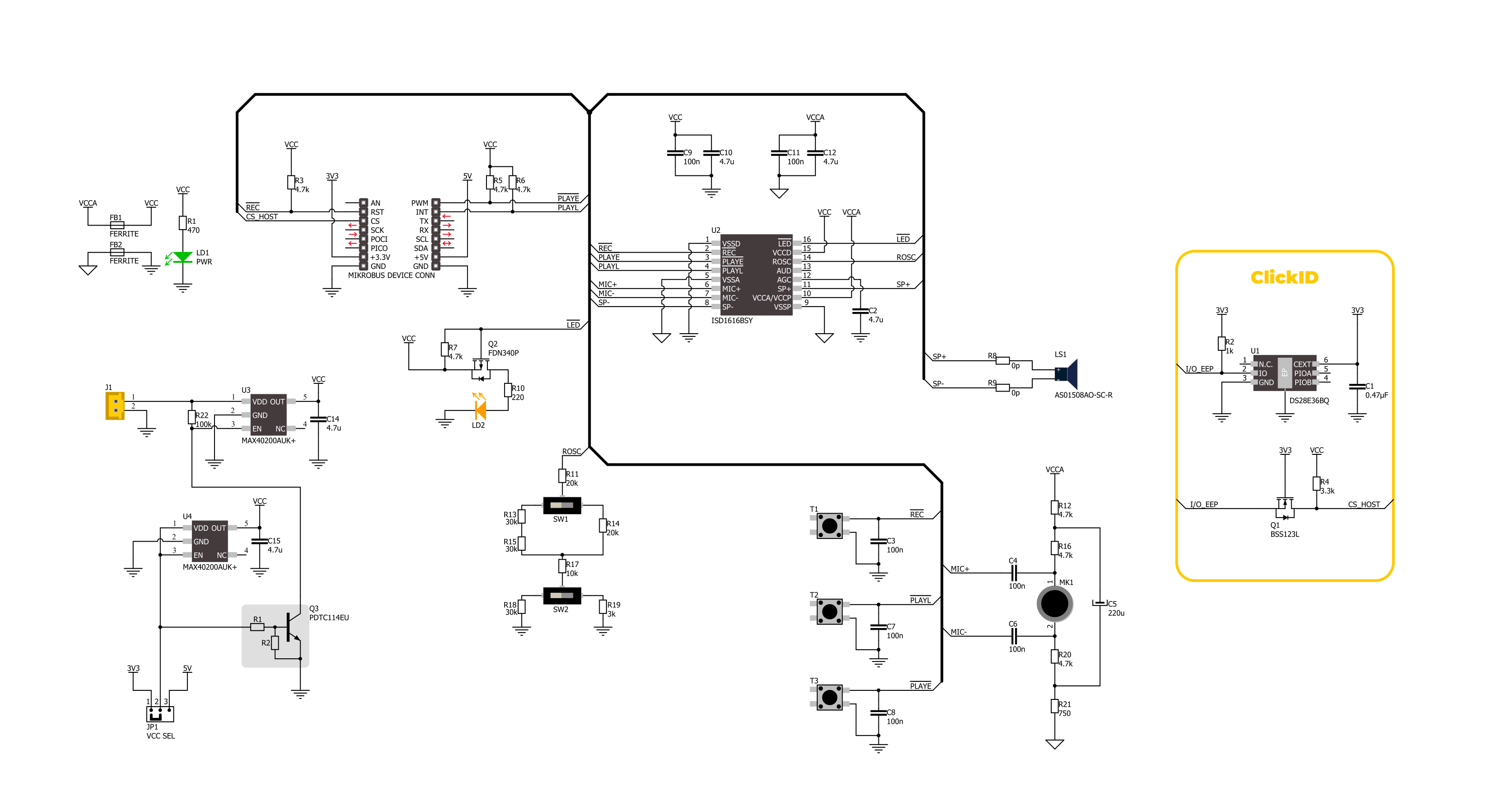
Rec&Play 2 Click is based on the ISD1616B, a single-message voice record and playback IC from Nuvoton designed for voice recording and playback applications. This highly integrated solution includes all the necessary components to deliver superior audio recording and playback functionality. It features an on-chip oscillator, a microphone preamplifier with Automatic Gain Control (AGC), and an omnidirectional electret microphone (CMC-2242PBL-A) for optimal audio capture. The built-in anti-aliasing filter ensures smooth, high-quality recording, while the Multi-Level Storage (MLS) array provides efficient data handling. Voice and audio data are stored directly in the onboard Flash memory without digital compression, ensuring high-quality playback. A smoothing filter and Pulse Width Modulation (PWM) Class D speaker driver control the integrated speaker (AS01508AO-SC-R), delivering clear and precise audio output. With zero-power message storage, recordings remain intact even without a power supply. Rec&Play 2 Click is ideal for various audio playback
applications, including alarms, voice prompts, and automated announcements, where clear and reliable audio is essential. The ISD1616B can be managed both manually and digitally. Manual control is available through dedicated buttons: REC, E, and L. The REC button enables voice recording, which continues as long as the button remains pressed. The E and L buttons handle playback, offering two distinct modes: the E button is used for edge-trigger playback, while the L button is for level-trigger playback. In edge-trigger playback mode, pressing the E button for longer than the specified debounce time initiates playback from the beginning of the memory, continuing until an End-Of-Message (EOM) marker is reached, after which the device automatically enters standby mode. In level-trigger playback mode, pressing the L button starts playback from the beginning of the memory, and it runs until an EOM marker is reached, then powers down automatically. These same functions can also be controlled digitally via the REC, PE, and PL pins on the mikroBUS™
socket. The message duration is user-selectable, ranging from 10 to 24 seconds, depending on the configuration of the onboard REC/Play Duration switches. In addition to these switches, the board features a visual guide to indicate the switch positions and corresponding recording/playback durations of 10, 16, 20, or 24 seconds. It also includes an orange status LED indicator, which stays illuminated during recording and blinks several times per second during playback, providing visual feedback on the operation status. This Click board™ can operate with either 3.3V or 5V logic voltage levels selected via the VCC SEL jumper. This way, both 3.3V and 5V capable MCUs can use the communication lines properly. It also supports battery power, enabling standalone applications without needing an external power supply. Additionally, this Click board™ comes equipped with a library containing easy-to-use functions and an example code that can be used as a reference for further development.

Features overview
Development board
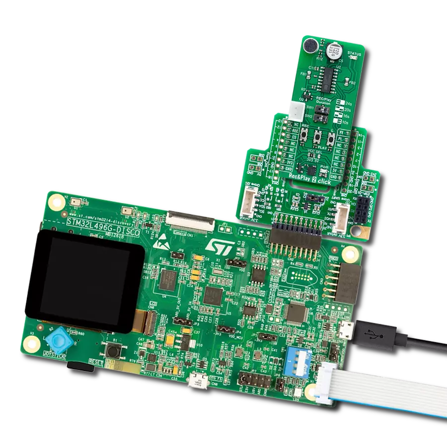
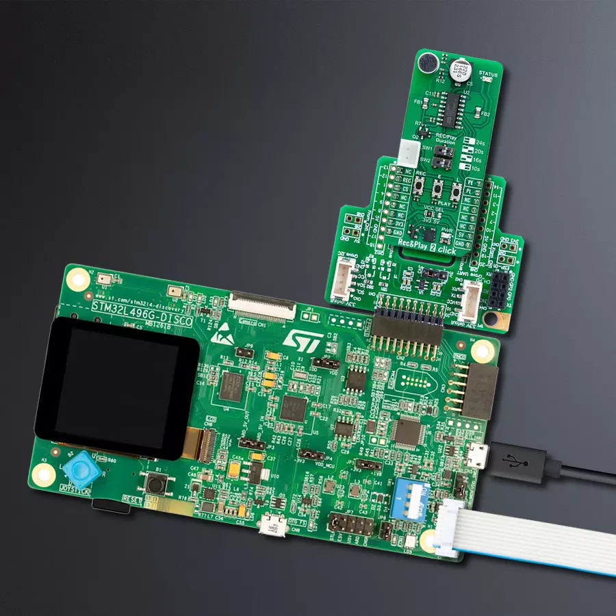
The 32L496GDISCOVERY Discovery kit serves as a comprehensive demonstration and development platform for the STM32L496AG microcontroller, featuring an Arm® Cortex®-M4 core. Designed for applications that demand a balance of high performance, advanced graphics, and ultra-low power consumption, this kit enables seamless prototyping for a wide range of embedded solutions. With its innovative energy-efficient
architecture, the STM32L496AG integrates extended RAM and the Chrom-ART Accelerator, enhancing graphics performance while maintaining low power consumption. This makes the kit particularly well-suited for applications involving audio processing, graphical user interfaces, and real-time data acquisition, where energy efficiency is a key requirement. For ease of development, the board includes an onboard ST-LINK/V2-1
debugger/programmer, providing a seamless out-of-the-box experience for loading, debugging, and testing applications without requiring additional hardware. The combination of low power features, enhanced memory capabilities, and built-in debugging tools makes the 32L496GDISCOVERY kit an ideal choice for prototyping advanced embedded systems with state-of-the-art energy efficiency.

Microcontroller Overview
MCU Card / MCU

Architecture
ARM Cortex-M4
MCU Memory (KB)
1024
Silicon Vendor
STMicroelectronics
Pin count
169
RAM (Bytes)
327680
Used MCU Pins
mikroBUS™ mapper
Take a closer look
Click board™ Schematic
Step by step
Project assembly

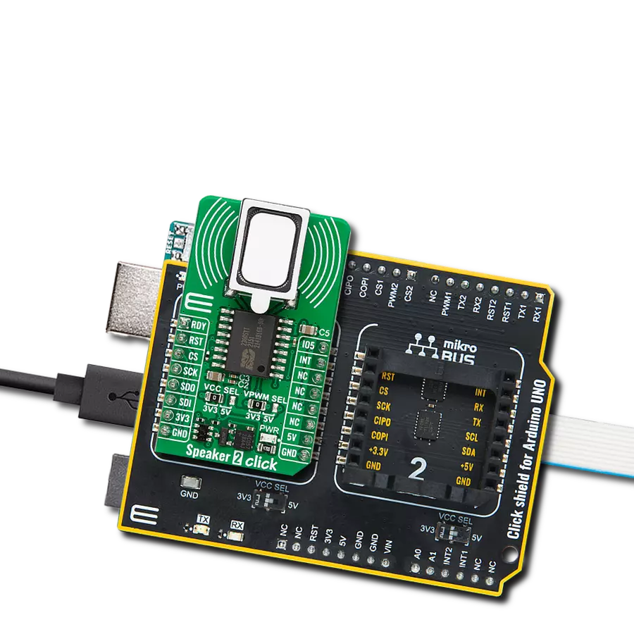
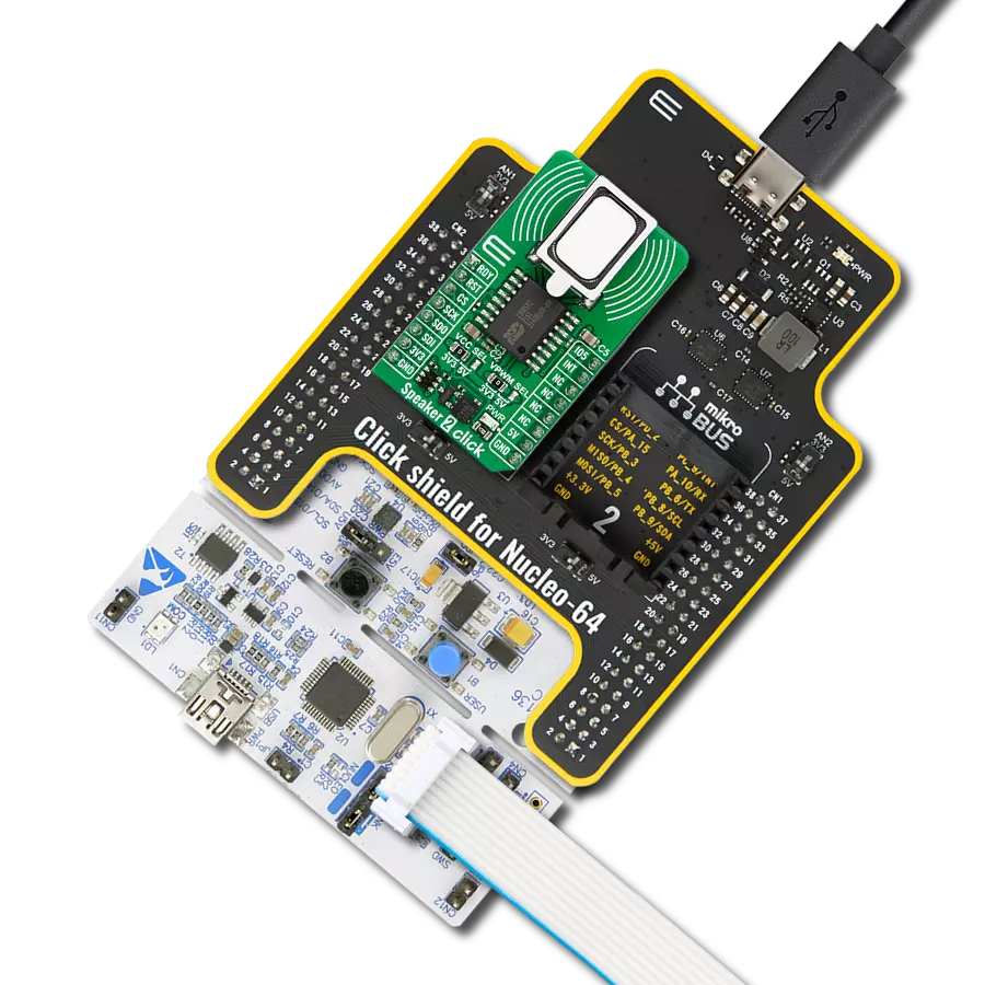
Start by selecting your development board and Click board™. Begin with the Discovery kit with STM32L496AG MCU as your development board.


Software Support
Library Description
This library contains API for Rec&Play 2 Click driver.
Key functions:
recnplay2_set_pl_pin- This function sets the PL pin on the selected level of Rec&Play 2 Click.recnplay2_record_sound- This function is used to record sound with Rec&Play 2 Click.recnplay2_play_sound- This function is used to play recorded sounds with Rec&Play 2 Click.
Open Source
Code example
The complete application code and a ready-to-use project are available through the NECTO Studio Package Manager for direct installation in the NECTO Studio. The application code can also be found on the MIKROE GitHub account.
/*!
 * @file main.c
 * @brief Rec N Play 2 Click Example.
 *
 * # Description
 * This example demonstrates the use of Rec N Play 2 Click board by
 * recording and then playing recorded sound.
 *
 * The demo application is composed of two sections :
 *
 * ## Application Init
 * Initializes the driver, performs the Click default configuration.
 *
 * ## Application Task
 * Recording sound for 5 seconds, then playing it back.
 *
 * @author Stefan Ilic
 *
 */

#include "board.h"
#include "log.h"
#include "recnplay2.h"

static recnplay2_t recnplay2;   /**< Rec N Play 2 Click driver object. */
static log_t logger;    /**< Logger object. */

#define RECORDING_LEN       5000

void application_init ( void )
{
    log_cfg_t log_cfg;  /**< Logger config object. */
    recnplay2_cfg_t recnplay2_cfg;  /**< Click config object. */

    /**
     * Logger initialization.
     * Default baud rate: 115200
     * Default log level: LOG_LEVEL_DEBUG
     * @note If USB_UART_RX and USB_UART_TX
     * are defined as HAL_PIN_NC, you will
     * need to define them manually for log to work.
     * See @b LOG_MAP_USB_UART macro definition for detailed explanation.
     */
    LOG_MAP_USB_UART( log_cfg );
    log_init( &logger, &log_cfg );
    log_info( &logger, " Application Init " );

    // Click initialization.
    recnplay2_cfg_setup( &recnplay2_cfg );
    RECNPLAY2_MAP_MIKROBUS( recnplay2_cfg, MIKROBUS_1 );
    if ( DIGITAL_OUT_UNSUPPORTED_PIN == recnplay2_init( &recnplay2, &recnplay2_cfg ) )
    {
        log_error( &logger, " Communication init." );
        for ( ; ; );
    }

    recnplay2_default_cfg ( &recnplay2 );

    log_info( &logger, " Application Task " );
}

void application_task ( void )
{
    log_printf( &logger, " Recording... \r\n" );
    recnplay2_record_sound( &recnplay2, RECORDING_LEN );
    Delay_ms ( 1000 );

    log_printf( &logger, " Playing... \r\n" );
    recnplay2_play_sound( &recnplay2, RECORDING_LEN );
    Delay_ms ( 1000 );
}

int main ( void )
{
    /* Do not remove this line or clock might not be set correctly. */
    #ifdef PREINIT_SUPPORTED
    preinit();
    #endif

    application_init( );

    for ( ; ; )
    {
        application_task( );
    }

    return 0;
}

// ------------------------------------------------------------------------ END
Additional Support
Resources
Category:Speakers