Host unforgettable parties with powerful audio, thanks to the MAX9717 and PIC32MZ2048EFM100
Elevate your audio world to new heights!
Published Oct 22, 2023
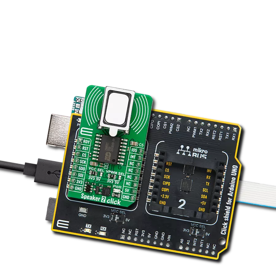
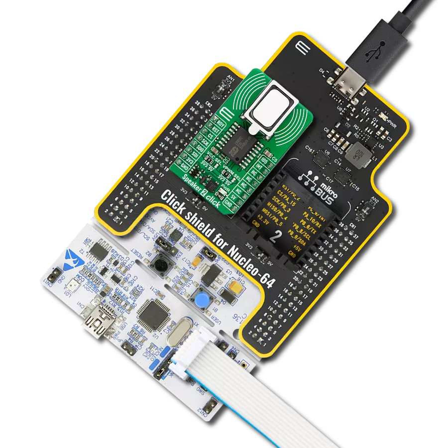
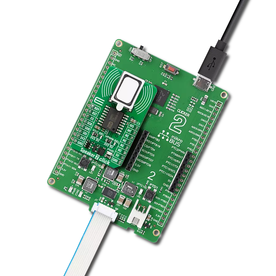
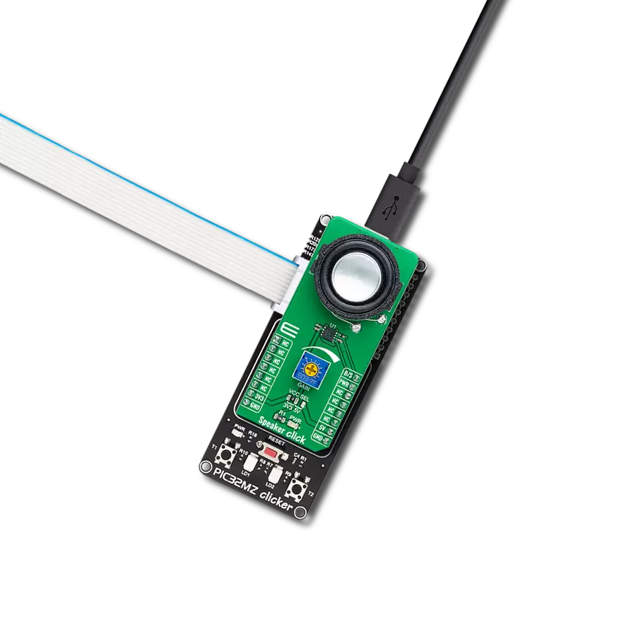
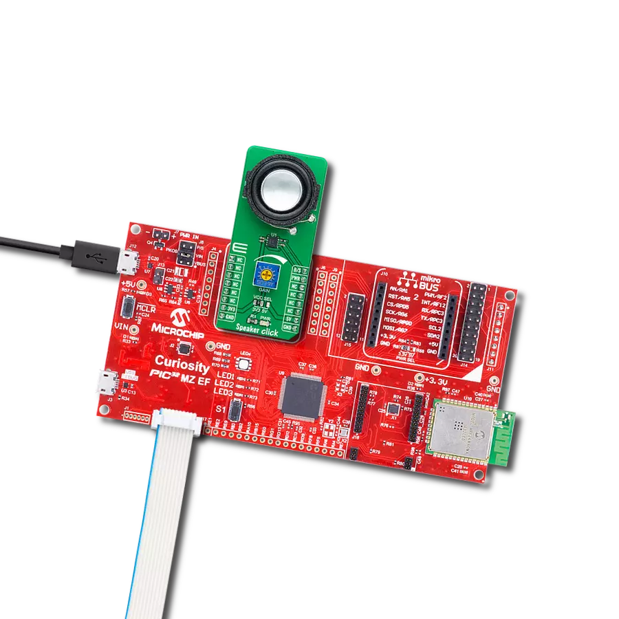
Click board™
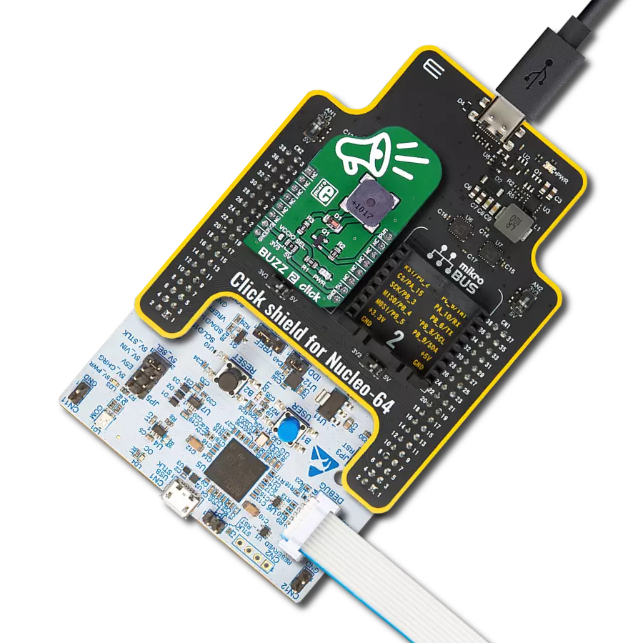
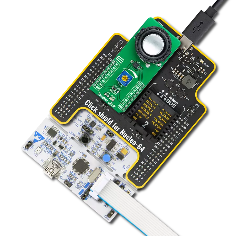
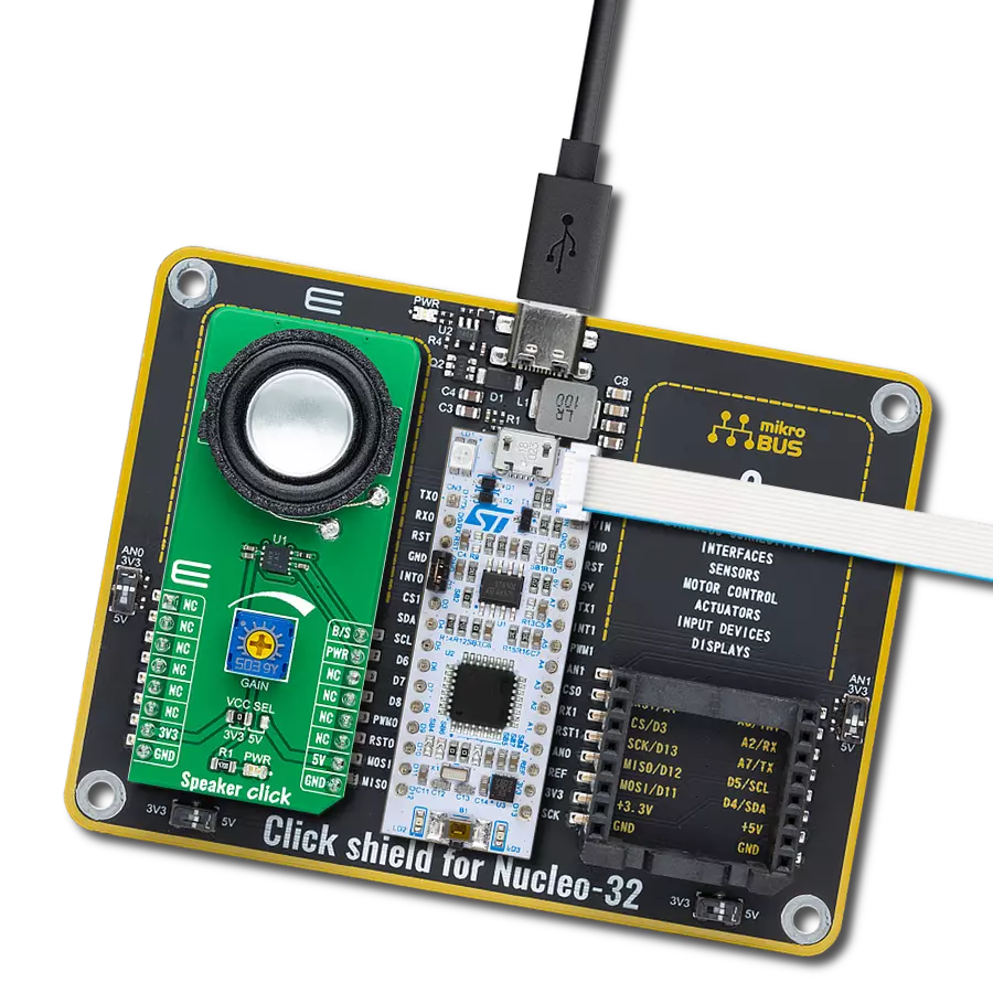
Speaker Click
Dev. board
Curiosity PIC32 MZ EF
Compiler
NECTO Studio
MCU
PIC32MZ2048EFM100
Embark on a transformative audio journey as you explore a speaker solution featuring a high-quality audio power amplifier, elevating your audio experience to new heights
A
A
Hardware Overview
How does it work?
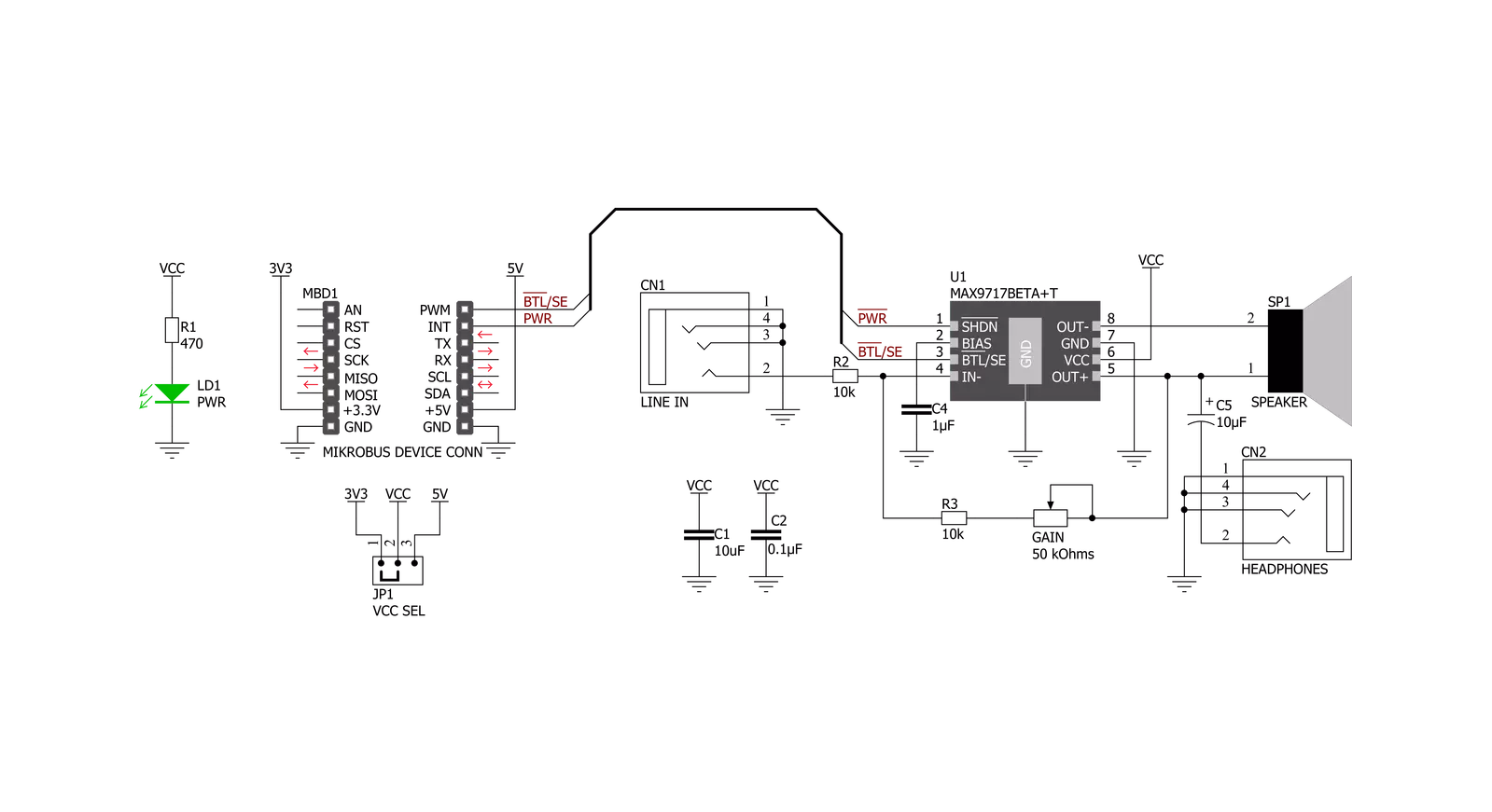
Speaker Click is based on the MAX9717, a 1.4W mono bridge-tied load (BTL) architecture audio power amplifier with a high-quality audio reproduction from Analog Devices. It delivers 1.4W continuous power into a 4Ω load from a single +5V supply or 350mW continuous power into an 8Ω load while operating from a single +3.3V supply. This device features Maxim’s industry-leading, comprehensive click-and-pop suppression that reduces audible clicks and pops during the Start-Up and Shutdown sequence. Output signal reproduction is possible through the onboard speaker and the headphone jack located on the bottom side of this Click board™. Speaker Click communicates with MCU using two GPIO pins routed on the PWM and INT pins of the
mikroBUS™ socket labeled B/S and PWR. The MAX9717 features a low-power shutdown mode that reduces quiescent current consumption to 10nA. Entering shutdown mode is possible through the PWR pin, which turns off the bias circuitry and forces the amplifier outputs to GND through an internal 20kΩ resistor. Driving the PWR to a low logic state will cause MAX9717 to enter shutdown mode while the high state will perform a normal operation. As mentioned, this Click board™ has a 20mm 4Ω Premium Micro Transducer onboard speaker for sound reproduction. This speaker features a neodymium-iron-boron magnet, a light aluminum cone, and a high-temperature polycarbonate frame with low resonant frequencies and a full-range
bandwidth. Also, the MAX9717 features a headphone sense input pin, labeled as B/S, that senses headphone connection to the device through a 3.5mm jack connector labeled HEADPHONES. This feature mutes the speaker while driving the headphones as a single-ended load. An adjustable potentiometer labeled GAIN adjusts the gain of the MAXS9717‘s internal amplifier. This Click board™ can operate with either 3.3V or 5V logic voltage levels selected via the VCC SEL jumper. This way, both 3.3V and 5V capable MCUs can use the communication lines properly. Also, this Click board™ comes equipped with a library containing easy-to-use functions and an example code that can be used as a reference for further development.

Features overview
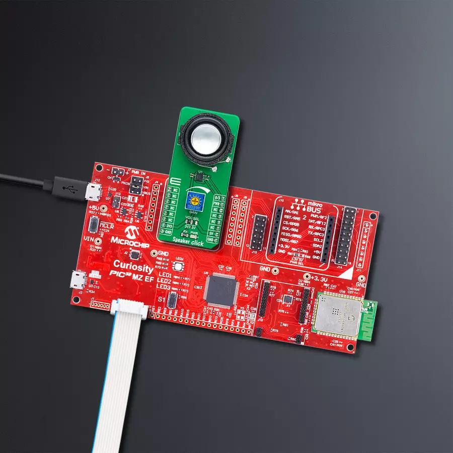
Development board
Curiosity PIC32 MZ EF development board is a fully integrated 32-bit development platform featuring the high-performance PIC32MZ EF Series (PIC32MZ2048EFM) that has a 2MB Flash, 512KB RAM, integrated FPU, Crypto accelerator, and excellent connectivity options. It includes an integrated programmer and debugger, requiring no additional hardware. Users can expand
functionality through MIKROE mikroBUS™ Click™ adapter boards, add Ethernet connectivity with the Microchip PHY daughter board, add WiFi connectivity capability using the Microchip expansions boards, and add audio input and output capability with Microchip audio daughter boards. These boards are fully integrated into PIC32’s powerful software framework, MPLAB Harmony,
which provides a flexible and modular interface to application development a rich set of inter-operable software stacks (TCP-IP, USB), and easy-to-use features. The Curiosity PIC32 MZ EF development board offers expansion capabilities making it an excellent choice for a rapid prototyping board in Connectivity, IOT, and general-purpose applications.

Microcontroller Overview
MCU Card / MCU

Architecture
PIC32
MCU Memory (KB)
2048
Silicon Vendor
Microchip
Pin count
100
RAM (Bytes)
524288
Used MCU Pins
mikroBUS™ mapper
Take a closer look
Click board™ Schematic
Step by step
Project assembly

Start by selecting your development board and Click board™. Begin with the Curiosity PIC32 MZ EF as your development board.


Software Support
Library Description
This library contains API for Speaker Click driver.
Key functions:
speaker_shutdown- Speaker shutdown mode functionspeaker_normal_operation- Speaker normal operation mode functionspeaker_enable_slave_amp- Speaker enables the slave amplifier function
Open Source
Code example
The complete application code and a ready-to-use project are available through the NECTO Studio Package Manager for direct installation in the NECTO Studio. The application code can also be found on the MIKROE GitHub account.
/*!
 * @file main.c
 * @brief Speaker Click Example.
 *
 * # Description
 * This library contains API for the Speaker Click driver.
 * This application controls the operating modes of the
 * Speaker Click board™.
 *
 * The demo application is composed of two sections :
 *
 * ## Application Init
 * Initialization of GPIO module and log UART.
 * After driver initialization, the application performs the default settings.
 *
 * ## Application Task
 * This is an example that shows the use of a Speaker Click board™.
 * The task of the application consists of
 * switching two modes of operation: normal and shutdown modes.
 * Results are being sent to the Usart Terminal where you can track their changes.
 *
 * @author Nenad Filipovic
 *
 */

#include "board.h"
#include "log.h"
#include "speaker.h"

static speaker_t speaker;       /**< Speaker Click driver object. */
static log_t logger;            /**< Logger object. */

void application_init ( void ) {
    log_cfg_t log_cfg;          /**< Logger config object. */
    speaker_cfg_t speaker_cfg;  /**< Click config object. */

    /**
     * Logger initialization.
     * Default baud rate: 115200
     * Default log level: LOG_LEVEL_DEBUG
     * @note If USB_UART_RX and USB_UART_TX
     * are defined as HAL_PIN_NC, you will
     * need to define them manually for log to work.
     * See @b LOG_MAP_USB_UART macro definition for detailed explanation.
     */
    LOG_MAP_USB_UART( log_cfg );
    log_init( &logger, &log_cfg );
    log_printf( &logger, "\r\n" );
    log_info( &logger, " Application Init " );

    // Click initialization.

    speaker_cfg_setup( &speaker_cfg );
    SPEAKER_MAP_MIKROBUS( speaker_cfg, MIKROBUS_1 );
    if ( speaker_init( &speaker, &speaker_cfg ) == DIGITAL_OUT_UNSUPPORTED_PIN ) {
        log_error( &logger, " Application Init Error. " );
        log_info( &logger, " Please, run program again... " );

        for ( ; ; );
    }
    speaker_default_cfg ( &speaker );
    log_info( &logger, " Application Task " );
    Delay_ms ( 100 );
}

void application_task ( void ) {
    log_printf( &logger, "-------------------------\r\n" );
    log_printf( &logger, "  Normal Operation Mode \r\n" );
    speaker_normal_operation( &speaker );
    // 10 seconds delay
    Delay_ms ( 1000 );
    Delay_ms ( 1000 );
    Delay_ms ( 1000 );
    Delay_ms ( 1000 );
    Delay_ms ( 1000 );
    Delay_ms ( 1000 );
    Delay_ms ( 1000 );
    Delay_ms ( 1000 );
    Delay_ms ( 1000 );
    Delay_ms ( 1000 );

    log_printf( &logger, "-------------------------\r\n" );
    log_printf( &logger, "   Enter Shutdown Mode  \r\n" );
    speaker_shutdown( &speaker );
    // 10 seconds delay
    Delay_ms ( 1000 );
    Delay_ms ( 1000 );
    Delay_ms ( 1000 );
    Delay_ms ( 1000 );
    Delay_ms ( 1000 );
    Delay_ms ( 1000 );
    Delay_ms ( 1000 );
    Delay_ms ( 1000 );
    Delay_ms ( 1000 );
    Delay_ms ( 1000 );
}

int main ( void )
{
    /* Do not remove this line or clock might not be set correctly. */
    #ifdef PREINIT_SUPPORTED
    preinit();
    #endif

    application_init( );

    for ( ; ; )
    {
        application_task( );
    }

    return 0;
}

// ------------------------------------------------------------------------ END
Additional Support
Resources
Category:Speakers