Create notification systems for various events or alarms with STM32F302VC and PAM8904
Alerts that demand attention: Next-gen buzzers that redefine signaling
Published Jul 22, 2025
Click board™
BUZZ 3 Click
Dev. board
CLICKER 4 for STM32F302VCT6
Compiler
NECTO Studio
MCU
STM32F302VC
Step into the future of audio signaling with next-gen buzzers and witness their transformative impact across a wide spectrum of industries and settings
A
A
Hardware Overview
How does it work?
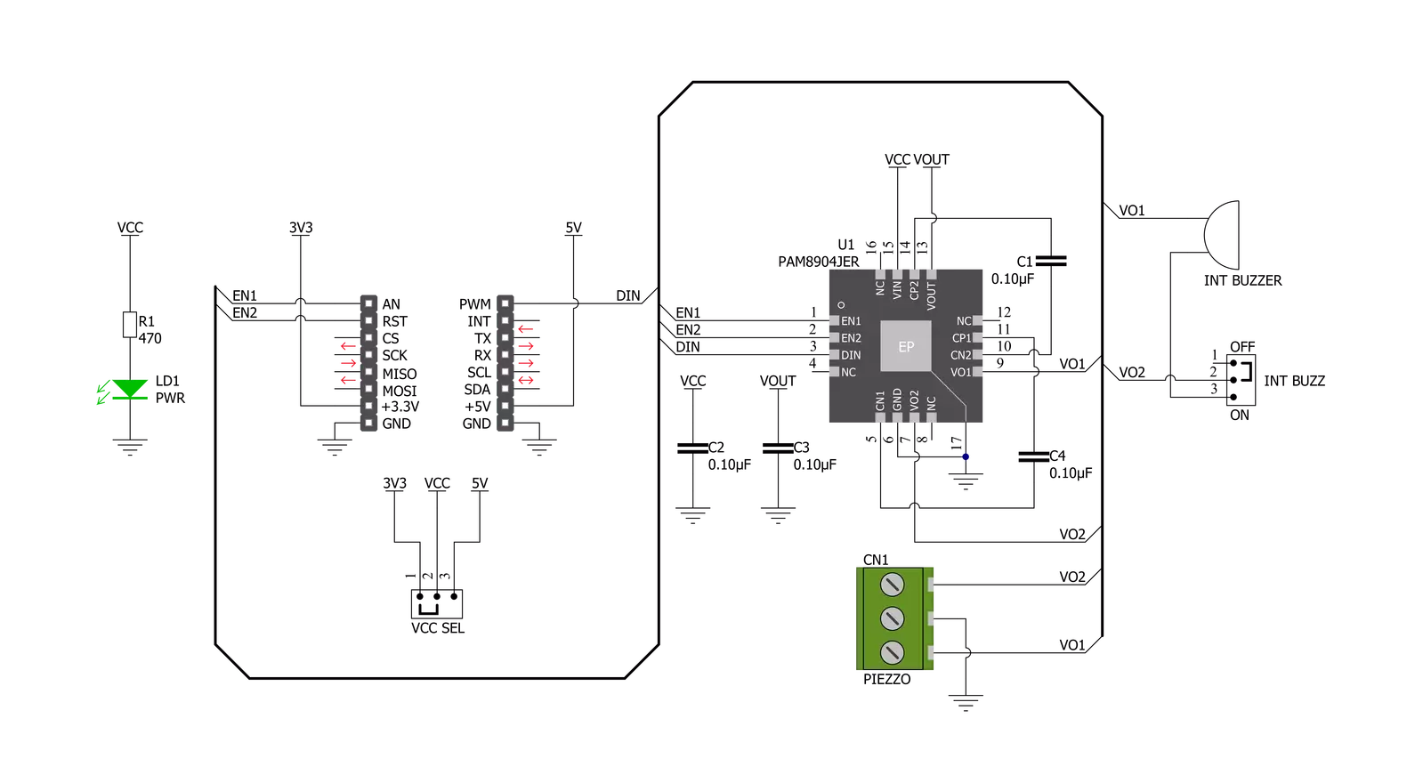
Buzz 3 Click is based on the PAM8904, a piezo-sounder driver with an integrated Multi-Mode charge pump boost converter from Diodes Incorporated. The PAM8904 is a switching driver with a multi-mode charge pump for piezo-sounder. Operating at a fixed frequency of 1MHz, the PAM8904 can drive a sounder load of up to 15nF, providing a 9V output with a minimal component footprint. For adjusting the piezoelectric sounder sound volume, the charge pump can operate in 1x, 2x, or 3x mode. It features thermal shutdown, over-current and voltage protection, and under-voltage lock-out and provides a small inrush current, low EMI, and high efficiency. The sounder driver helps to keep current consumption low and battery life long by employing built-in automatic shutdown and wake-up functions. For example, active current consumption is just 300µA in 1x mode, with an
input voltage of 3V, input frequency of 4kHz, and driving a 15nF piezo. In shutdown mode, the quiescent current is less than 1µA. The Charge Pump Mode pins, EN1 and EN2, are used to set the charge pump into mode 1xVDD, 2xVDD, 3xVDD, or they can be used to put the PAM8904 into a forced low-current Shutdown Mode. The device enters the Normal Operation Mode when one or both EN pins are pulled high. Once the PAM8904 senses a valid signal on the DIN pin, the charge pump will start and provide the desired voltage on the VOUT pin, and the output drive lines labeled as VO1 and VO2 will become active after a period of between 270μs and 350μs depending on the selected Mode. If a valid signal on the DIN line disappears, the PAM8904 will detect that disappearance and then wait 42ms to ensure its disappearance. If, even after this period, there is no valid signal on the DIN line, the PAM8904 switches
to low-current Standby Mode. Buzz 3 Click establishes communication with MCU using several GPIO pins routed on the RST, AN, and PWM pins of the mikroBUS™ socket labeled EN1, EN2, and DIN. There is also a jumper setting labeled as INT BUZZ used to choose between single-ended and differential load configurations and between driving either the onboard piezo-sounder or an externally connected piezo-sounder. This Click board™ can operate with either 3.3V or 5V logic voltage levels selected via the VCC SEL jumper. This way, both 3.3V and 5V capable MCUs can use the communication lines properly. Also, this Click board™ comes equipped with a library containing easy-to-use functions and an example code that can be used as a reference for further development.

Features overview
Development board
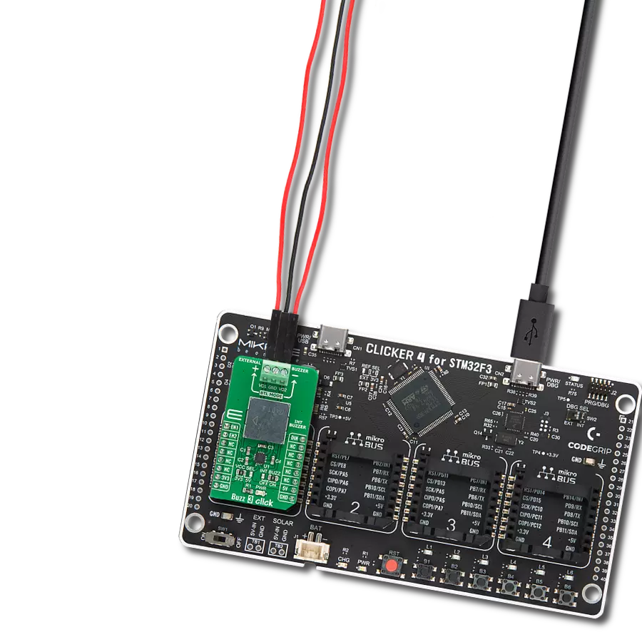
Clicker 4 for STM32F3 is a compact development board designed as a complete solution, you can use it to quickly build your own gadgets with unique functionalities. Featuring a STM32F302VCT6, four mikroBUS™ sockets for Click boards™ connectivity, power managment, and more, it represents a perfect solution for the rapid development of many different types of applications. At its core, there is a STM32F302VCT6 MCU, a powerful microcontroller by STMicroelectronics, based on the high-
performance Arm® Cortex®-M4 32-bit processor core operating at up to 168 MHz frequency. It provides sufficient processing power for the most demanding tasks, allowing Clicker 4 to adapt to any specific application requirements. Besides two 1x20 pin headers, four improved mikroBUS™ sockets represent the most distinctive connectivity feature, allowing access to a huge base of Click boards™, growing on a daily basis. Each section of Clicker 4 is clearly marked, offering an intuitive and clean interface. This makes working with the development
board much simpler and thus, faster. The usability of Clicker 4 doesn’t end with its ability to accelerate the prototyping and application development stages: it is designed as a complete solution which can be implemented directly into any project, with no additional hardware modifications required. Four mounting holes [4.2mm/0.165”] at all four corners allow simple installation by using mounting screws. For most applications, a nice stylish casing is all that is needed to turn the Clicker 4 development board into a fully functional, custom design.

Microcontroller Overview
MCU Card / MCU

Architecture
ARM Cortex-M4
MCU Memory (KB)
256
Silicon Vendor
STMicroelectronics
Pin count
100
RAM (Bytes)
40960
Used MCU Pins
mikroBUS™ mapper
Take a closer look
Click board™ Schematic
Step by step
Project assembly

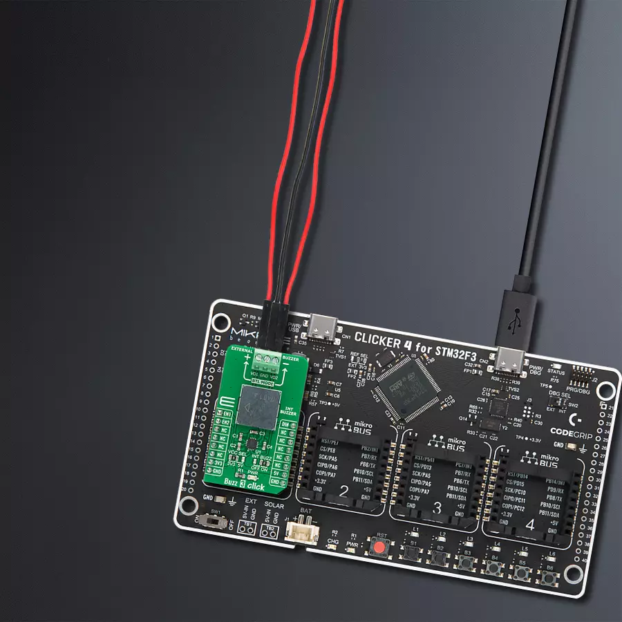
Start by selecting your development board and Click board™. Begin with the CLICKER 4 for STM32F302VCT6 as your development board.


Software Support
Library Description
This library contains API for BUZZ 3 Click driver.
Key functions:
buzz3_pwm_start- This function starts the PWM module outputbuzz3_set_gain_operating_mode- The function set gain operating mode of the PAM8904 piezo sounder driver with integrated charge pump boost converter on Buzz 3 Clickbuzz3_play_sound- This function plays sound on buzzer
Open Source
Code example
The complete application code and a ready-to-use project are available through the NECTO Studio Package Manager for direct installation in the NECTO Studio. The application code can also be found on the MIKROE GitHub account.
/*!
 * @file main.c
 * @brief Buzz3 Click example
 *
 * # Description
 * This example demonstrates the use of Buzz 3 Click boards with PAM8904 for play the Imperial March.
 * PAM8904 is piezo-sounder driver with an integrated Multi-Mode charge pump boost converter from Diodes Incorporated.
 *
 * The demo application is composed of two sections :
 *
 * ## Application Init
 * Initializes GPIO, set AN and RST pin as outputs, begins to write a log.
 * Initialization driver enables - GPIO and configures the appropriate MCU pin for
 * sound generation, also write log.
 *
 * ## Application Task
 * Plays the Imperial March melody. Also logs an appropriate message on the USB UART.
 *
 * Additional Functions :
 * - void buzz3_melody( void ) - This function plays the Imperial March melody.
 *
 * @note
 * The minimal PWM Clock frequency required for this example is the frequency of tone C6 - 1047 Hz.
 * So, in order to run this example and play all tones correctly, the user will need to decrease
 * the MCU's main clock frequency in MCU Settings for the certain architectures
 * in order to get the required PWM clock frequency.
 *
 * @author Jelena Milosavljevic
 *
 */

#include "board.h"
#include "log.h"
#include "buzz3.h"

#define W 4*Q         // Whole 4/4 - 4 Beats
#define H 2*Q         // Half 2/4 - 2 Beats
#define Q 250         // Quarter 1/4 - 1 Beat
#define E Q/2         // Eighth 1/8 - 1/2 Beat
#define S Q/4         // Sixteenth 1/16 - 1/4 Beat


static buzz3_t buzz3;
static log_t logger;

void buzz3_melody ( void ) {
    buzz3_play_sound(&buzz3, BUZZ3_NOTE_A6, Q );
    Delay_ms ( 1 + Q );
    buzz3_play_sound(&buzz3, BUZZ3_NOTE_A6, Q );
    Delay_ms ( 1 + Q );
    buzz3_play_sound(&buzz3, BUZZ3_NOTE_A6, Q );
    Delay_ms ( 1 + Q );
    buzz3_play_sound(&buzz3, BUZZ3_NOTE_F6, E + S );
    Delay_ms ( 1 + E + S );
    buzz3_play_sound(&buzz3, BUZZ3_NOTE_C7, S );
    Delay_ms ( 1 + S );

    buzz3_play_sound(&buzz3, BUZZ3_NOTE_A6, Q );
    Delay_ms ( 1 + Q );
    buzz3_play_sound(&buzz3, BUZZ3_NOTE_F6, E + S );
    Delay_ms ( 1 + E + S );
    buzz3_play_sound(&buzz3, BUZZ3_NOTE_C7, S );
    Delay_ms ( 1 + S );
    buzz3_play_sound(&buzz3, BUZZ3_NOTE_A6, H );
    Delay_ms ( 1 + H );

    buzz3_play_sound(&buzz3, BUZZ3_NOTE_E7, Q );
    Delay_ms ( 1 + Q );
    buzz3_play_sound(&buzz3, BUZZ3_NOTE_E7, Q );
    Delay_ms ( 1 + Q );
    buzz3_play_sound(&buzz3, BUZZ3_NOTE_E7, Q );
    Delay_ms ( 1 + Q );
    buzz3_play_sound(&buzz3, BUZZ3_NOTE_F7, E + S );
    Delay_ms ( 1 + E + S );
    buzz3_play_sound(&buzz3, BUZZ3_NOTE_C7, S );
    Delay_ms ( 1 + S );

    buzz3_play_sound(&buzz3, BUZZ3_NOTE_Ab6, Q );
    Delay_ms ( 1 + Q );
    buzz3_play_sound(&buzz3, BUZZ3_NOTE_F6, E + S );
    Delay_ms ( 1 + E + S );
    buzz3_play_sound(&buzz3, BUZZ3_NOTE_C7, S );
    Delay_ms ( 1 + S );
    buzz3_play_sound(&buzz3, BUZZ3_NOTE_A6, H );
    Delay_ms ( 1 + H );

    buzz3_play_sound(&buzz3, BUZZ3_NOTE_A7, Q );
    Delay_ms ( 1 + Q );
    buzz3_play_sound(&buzz3, BUZZ3_NOTE_A6, E + S );
    Delay_ms ( 1 + E + S );
    buzz3_play_sound(&buzz3, BUZZ3_NOTE_A6, S );
    Delay_ms ( 1 + S );
    buzz3_play_sound(&buzz3, BUZZ3_NOTE_A7, Q );
    Delay_ms ( 1 + Q );
    buzz3_play_sound(&buzz3, BUZZ3_NOTE_Ab7, E + S );
    Delay_ms ( 1 + E + S );
    buzz3_play_sound(&buzz3, BUZZ3_NOTE_G7, S );
    Delay_ms ( 1 + S );

    buzz3_play_sound(&buzz3, BUZZ3_NOTE_Gb7, S );
    Delay_ms ( 1 + S );
    buzz3_play_sound(&buzz3, BUZZ3_NOTE_E7, Q );
    Delay_ms ( 1 + Q );
    buzz3_play_sound(&buzz3, BUZZ3_NOTE_F7, E );
    Delay_ms ( 1 + E );
    Delay_ms ( 1 + E );
    buzz3_play_sound(&buzz3, BUZZ3_NOTE_Bb6, E );
    Delay_ms ( 1 + E );
    buzz3_play_sound(&buzz3, BUZZ3_NOTE_Eb7, Q );
    Delay_ms ( 1 + Q );
    buzz3_play_sound(&buzz3, BUZZ3_NOTE_D7, E + S );
    Delay_ms ( 1 + E + S );
    buzz3_play_sound(&buzz3, BUZZ3_NOTE_Db7, S );
    Delay_ms ( 1 + S );

    buzz3_play_sound(&buzz3, BUZZ3_NOTE_C7, S );
    Delay_ms ( 1 + S );
    buzz3_play_sound(&buzz3, BUZZ3_NOTE_B6, S );
    Delay_ms ( 1 + S );
    buzz3_play_sound(&buzz3, BUZZ3_NOTE_C7, E );
    Delay_ms ( 1 + E );
    Delay_ms ( 1 + E );
    buzz3_play_sound(&buzz3, BUZZ3_NOTE_F6, E );
    Delay_ms ( 1 + E );
    buzz3_play_sound(&buzz3, BUZZ3_NOTE_Ab6, Q );
    Delay_ms ( 1 + Q );
    buzz3_play_sound(&buzz3, BUZZ3_NOTE_F6, E + S );
    Delay_ms ( 1 + E + S );
    buzz3_play_sound(&buzz3, BUZZ3_NOTE_A6, S );
    Delay_ms ( 1 + S );

    buzz3_play_sound(&buzz3, BUZZ3_NOTE_C7, Q );
    Delay_ms ( 1 + Q );
    buzz3_play_sound(&buzz3, BUZZ3_NOTE_A6, E + S );
    Delay_ms ( 1 + E + S );
    buzz3_play_sound(&buzz3, BUZZ3_NOTE_C7, S );
    Delay_ms ( 1 + S );
    buzz3_play_sound(&buzz3, BUZZ3_NOTE_E7, H );
    Delay_ms ( 1 + H );

    buzz3_play_sound(&buzz3, BUZZ3_NOTE_A7, Q );
    Delay_ms ( 1 + Q );
    buzz3_play_sound(&buzz3, BUZZ3_NOTE_A6, E + S );
    Delay_ms ( 1 + E + S );
    buzz3_play_sound(&buzz3, BUZZ3_NOTE_A6, S );
    Delay_ms ( 1 + S );
    buzz3_play_sound(&buzz3, BUZZ3_NOTE_A7, Q );
    Delay_ms ( 1 + Q );
    buzz3_play_sound(&buzz3, BUZZ3_NOTE_Ab7, E + S );
    Delay_ms ( 1 + E + S );
    buzz3_play_sound(&buzz3, BUZZ3_NOTE_G7, S );
    Delay_ms ( 1 + S );

    buzz3_play_sound(&buzz3, BUZZ3_NOTE_Gb7, S );
    Delay_ms ( 1 + S );
    buzz3_play_sound(&buzz3, BUZZ3_NOTE_E7, S );
    Delay_ms ( 1 + S );
    buzz3_play_sound(&buzz3, BUZZ3_NOTE_F7, E );
    Delay_ms ( 1 + E );
    Delay_ms ( 1 + E );
    buzz3_play_sound(&buzz3, BUZZ3_NOTE_Bb6, E );
    Delay_ms ( 1 + E );
    buzz3_play_sound(&buzz3, BUZZ3_NOTE_Eb7, Q );
    Delay_ms ( 1 + Q );
    buzz3_play_sound(&buzz3, BUZZ3_NOTE_D7, E + S );
    Delay_ms ( 1 + E + S );
    buzz3_play_sound(&buzz3, BUZZ3_NOTE_Db7, S );
    Delay_ms ( 1 + S );

    buzz3_play_sound(&buzz3, BUZZ3_NOTE_C7, S );
    Delay_ms ( 1 + S );
    buzz3_play_sound(&buzz3, BUZZ3_NOTE_B6, S );
    Delay_ms ( 1 + S );
    buzz3_play_sound(&buzz3, BUZZ3_NOTE_C7, E );
    Delay_ms ( 1 + E );
    Delay_ms ( 1 + E );
    buzz3_play_sound(&buzz3, BUZZ3_NOTE_F6, E );
    Delay_ms ( 1 + E );
    buzz3_play_sound(&buzz3, BUZZ3_NOTE_Ab6, Q );
    Delay_ms ( 1 + Q );
    buzz3_play_sound(&buzz3, BUZZ3_NOTE_F6, E + S );
    Delay_ms ( 1 + E + S );
    buzz3_play_sound(&buzz3, BUZZ3_NOTE_C7, S );
    Delay_ms ( 1 + S );

    buzz3_play_sound(&buzz3, BUZZ3_NOTE_A6, Q );
    Delay_ms ( 1 + Q );
    buzz3_play_sound(&buzz3, BUZZ3_NOTE_F6, E + S );
    Delay_ms ( 1 + E + S );
    buzz3_play_sound(&buzz3, BUZZ3_NOTE_C7, S );
    Delay_ms ( 1 + S );
    buzz3_play_sound(&buzz3, BUZZ3_NOTE_Ab6, H );
    Delay_ms ( 1 + H );
}

void application_init ( void )
{
    log_cfg_t log_cfg;          /**< Logger config object. */
    buzz3_cfg_t buzz3_cfg;      /**< Click config object. */

    /**
     * Logger initialization.
     * Default baud rate: 115200
     * Default log level: LOG_LEVEL_DEBUG
     * @note If USB_UART_RX and USB_UART_TX
     * are defined as HAL_PIN_NC, you will
     * need to define them manually for log to work.
     * See @b LOG_MAP_USB_UART macro definition for detailed explanation.
     */
    LOG_MAP_USB_UART( log_cfg );
    log_init( &logger, &log_cfg );
    log_info( &logger, " Application Init " );

    // Click initialization.

    buzz3_cfg_setup( &buzz3_cfg );
    BUZZ3_MAP_MIKROBUS( buzz3_cfg, MIKROBUS_1 );
    err_t init_flag  = buzz3_init( &buzz3, &buzz3_cfg );
    if ( PWM_ERROR == init_flag )
    {
        log_error( &logger, " Application Init Error. " );
        log_info( &logger, " Please, run program again... " );

        for ( ; ; );
    }

    buzz3_default_cfg ( &buzz3 );
    buzz3_set_duty_cycle ( &buzz3, 0.0 );
    log_printf( &logger, "---------------------\r\n" );
    log_printf( &logger, " Set the gain to x1  \r\n" );
    log_printf( &logger, "---------------------\r\n" );
    Delay_ms ( 100 );
    buzz3_pwm_start( &buzz3 );
    buzz3_set_gain_operating_mode( &buzz3, BUZZ3_OP_MODE_GAIN_x1 );

    log_info( &logger, " Application Task " );
}

void application_task ( void )
{
    log_printf( &logger, "   Play the music    \r\n" );
    buzz3_melody( );
    log_printf( &logger, "---------------------\r\n" );
    Delay_ms ( 1000 );
}

int main ( void )
{
    /* Do not remove this line or clock might not be set correctly. */
    #ifdef PREINIT_SUPPORTED
    preinit();
    #endif

    application_init( );

    for ( ; ; )
    {
        application_task( );
    }

    return 0;
}

// ------------------------------------------------------------------------ END
Additional Support
Resources
Category:Speakers