Create a rainbow animation with KTD2052A and STM32L496AG
Versatile and creative platform for various applications

Published Jul 22, 2025
Click board™
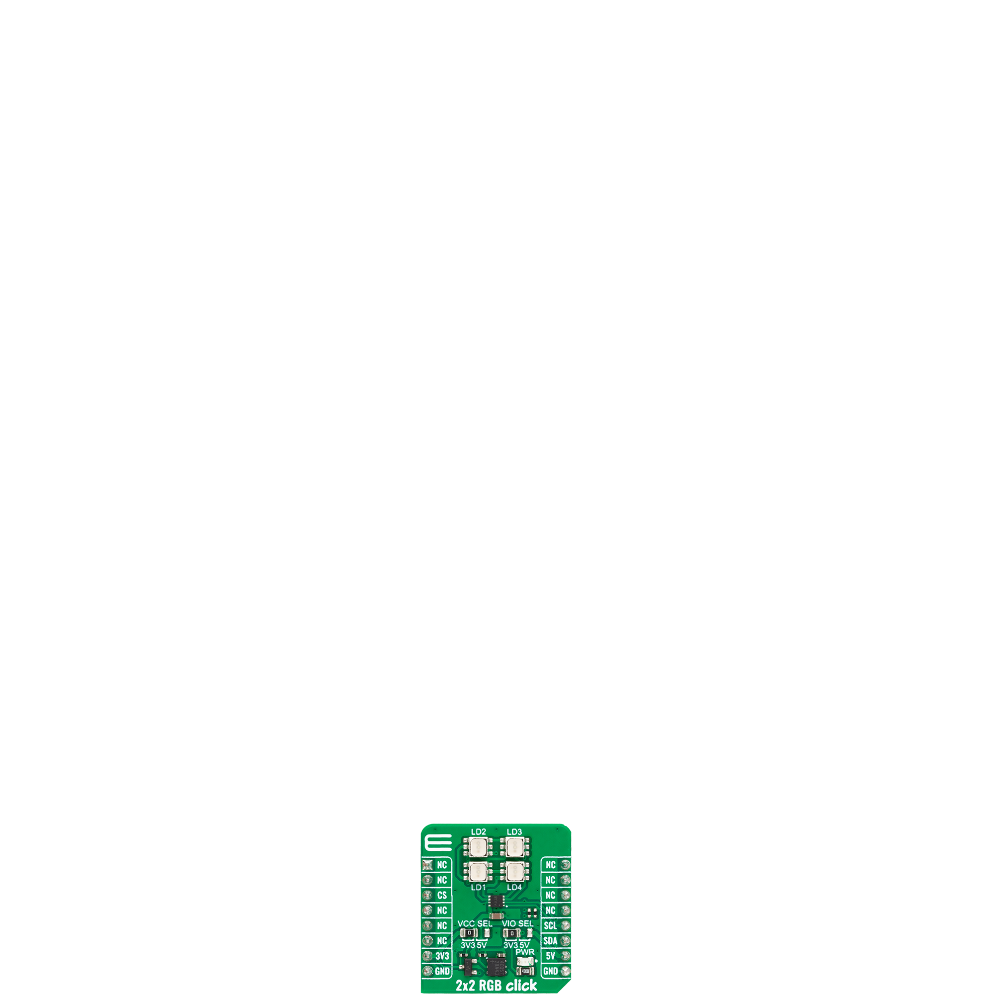
2x2 RGB Click
Dev. board
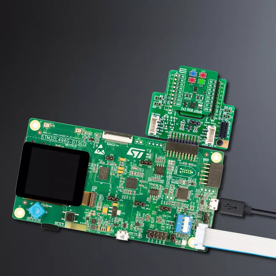
Discovery kit with STM32L496AG MCU
Compiler
NECTO Studio
MCU
STM32L496AG
Command 4 ultra-bright RGB LEDs to vividly showcase your information
A
A
Hardware Overview
How does it work?
2x2 RGB Click is based on the KTD2052A, a 12-channel RGB LED driver from Kinetic Technologies. It can be powered from mikroBUS™ socket supply rails, both with 3.3V and 5V selected over the VCC SEL. A 4-wire bus is multiplexed to reduce the pin count, as each pin on the bus integrates a switch to the input voltage and a programmable low-dropout current sink regulator. The driver is capable of 14 million colors with a controllable LED current from 125μA to 24mA in 125μA steps. There is also a night mode (8μA to
1.5mA in 8μA steps). There are 12 independent exponential fade engines with ultra-smooth 3072-step fade resolution and a 3-bit programmable fade rate. 2x2 RGB Click uses a standard 2-Wire I2C interface to communicate with the host MCU, supporting clock frequency of up to 1MHz. The I2C interface allows you to set the ON/OFF status and individual LED current, as well as adjust the fade rate. An internal flexible pattern generator with a watchdog counter enables set-and-forget pattern executions, while more complex patterns may be
executed from system firmware via the I2C interface. This Click board™ can operate with either 3.3V or 5V logic voltage levels selected via the VIO SEL jumper. This way, both 3.3V and 5V capable MCUs can use the communication lines properly. Also, this Click board™ comes equipped with a library containing easy-to-use functions and an example code that can be used as a reference for further development.

Features overview
Development board
The 32L496GDISCOVERY Discovery kit serves as a comprehensive demonstration and development platform for the STM32L496AG microcontroller, featuring an Arm® Cortex®-M4 core. Designed for applications that demand a balance of high performance, advanced graphics, and ultra-low power consumption, this kit enables seamless prototyping for a wide range of embedded solutions. With its innovative energy-efficient
architecture, the STM32L496AG integrates extended RAM and the Chrom-ART Accelerator, enhancing graphics performance while maintaining low power consumption. This makes the kit particularly well-suited for applications involving audio processing, graphical user interfaces, and real-time data acquisition, where energy efficiency is a key requirement. For ease of development, the board includes an onboard ST-LINK/V2-1
debugger/programmer, providing a seamless out-of-the-box experience for loading, debugging, and testing applications without requiring additional hardware. The combination of low power features, enhanced memory capabilities, and built-in debugging tools makes the 32L496GDISCOVERY kit an ideal choice for prototyping advanced embedded systems with state-of-the-art energy efficiency.

Microcontroller Overview
MCU Card / MCU

Architecture
ARM Cortex-M4
MCU Memory (KB)
1024
Silicon Vendor
STMicroelectronics
Pin count
169
RAM (Bytes)
327680
Used MCU Pins
mikroBUS™ mapper
Take a closer look
Click board™ Schematic

Step by step
Project assembly

Start by selecting your development board and Click board™. Begin with the Discovery kit with STM32L496AG MCU as your development board.


Software Support
Library Description
This library contains API for 2x2 RGB Click driver.
Key functions:
c2x2rgb_set_rgb_led- 2x2 RGB set RGB LED function.c2x2rgb_set_control- 2x2 RGB set control function.
Open Source
Code example
The complete application code and a ready-to-use project are available through the NECTO Studio Package Manager for direct installation in the NECTO Studio. The application code can also be found on the MIKROE GitHub account.
/*!
 * @file main.c
 * @brief 2x2 RGB Click example
 *
 * # Description
 * This example demonstrates the use of the 2x2 RGB Click board™
 * by controlling the color of the LEDs [1-4].
 *
 * The demo application is composed of two sections :
 *
 * ## Application Init
 * Initialization of SPI module and log UART.
 * After driver initialization, the app executes a default configuration.
 *
 * ## Application Task
 * This simple example shows all LEDs in different colors.
 * These LEDs actually consist of three single-colored LEDs (Red, Green and Blue) in a single package.
 * Various colors can be reproduced by mixing the intensity of each LED.
 *
 * @author Mikroe Team
 *
 */

#include "board.h"
#include "log.h"
#include "c2x2rgb.h"

#define DEMO_LED_CURRENT    600

static c2x2rgb_t c2x2rgb;
static log_t logger;

void application_init ( void )
{
    log_cfg_t log_cfg;  /**< Logger config object. */
    c2x2rgb_cfg_t c2x2rgb_cfg;  /**< Click config object. */

    /**
     * Logger initialization.
     * Default baud rate: 115200
     * Default log level: LOG_LEVEL_DEBUG
     * @note If USB_UART_RX and USB_UART_TX
     * are defined as HAL_PIN_NC, you will
     * need to define them manually for log to work.
     * See @b LOG_MAP_USB_UART macro definition for detailed explanation.
     */
    LOG_MAP_USB_UART( log_cfg );
    log_init( &logger, &log_cfg );
    log_info( &logger, " Application Init " );

    // Click initialization.
    c2x2rgb_cfg_setup( &c2x2rgb_cfg );
    C2X2RGB_MAP_MIKROBUS( c2x2rgb_cfg, MIKROBUS_1 );
    if ( I2C_MASTER_ERROR == c2x2rgb_init( &c2x2rgb, &c2x2rgb_cfg ) )
    {
        log_error( &logger, " Communication init." );
        for ( ; ; );
    }

    if ( C2X2RGB_ERROR == c2x2rgb_default_cfg ( &c2x2rgb ) )
    {
        log_error( &logger, " Default configuration." );
        for ( ; ; );
    }

    log_info( &logger, " Application Task " );
    log_printf( &logger, "----------------" );
    Delay_ms ( 100 );
}

void application_task ( void )
{
    log_printf( &logger, "\r\nRED: " );
    for ( uint8_t led_pos = C2X2RGB_SET_LD1; led_pos <= C2X2RGB_SET_LD4; led_pos++ )
    {
        if ( C2X2RGB_OK == c2x2rgb_set_rgb_led( &c2x2rgb, led_pos, DEMO_LED_CURRENT,
                                                                   C2X2RGB_LED_CURRENT_OFF,
                                                                   C2X2RGB_LED_CURRENT_OFF ) )
        {
            log_printf( &logger, "LD%d ", ( uint16_t ) led_pos );
        }
        Delay_ms ( 200 );
    }

    log_printf( &logger, "\r\nGREEN: " );
    for ( uint8_t led_pos = C2X2RGB_SET_LD1; led_pos <= C2X2RGB_SET_LD4; led_pos++ )
    {
        if ( C2X2RGB_OK == c2x2rgb_set_rgb_led( &c2x2rgb, led_pos, C2X2RGB_LED_CURRENT_OFF,
                                                                   DEMO_LED_CURRENT,
                                                                   C2X2RGB_LED_CURRENT_OFF ) )
        {
            log_printf( &logger, "LD%d ", ( uint16_t ) led_pos );
        }
        Delay_ms ( 200 );
    }

    log_printf( &logger, "\r\nBLUE: " );
    for ( uint8_t led_pos = C2X2RGB_SET_LD1; led_pos <= C2X2RGB_SET_LD4; led_pos++ )
    {
        if ( C2X2RGB_OK == c2x2rgb_set_rgb_led( &c2x2rgb, led_pos, C2X2RGB_LED_CURRENT_OFF,
                                                                   C2X2RGB_LED_CURRENT_OFF,
                                                                   DEMO_LED_CURRENT ) )
        {
            log_printf( &logger, "LD%d ", ( uint16_t ) led_pos );
        }
        Delay_ms ( 200 );
    }

    log_printf( &logger, "\r\nWHITE: " );
    for ( uint8_t led_pos = C2X2RGB_SET_LD1; led_pos <= C2X2RGB_SET_LD4; led_pos++ )
    {
        if ( C2X2RGB_OK == c2x2rgb_set_rgb_led( &c2x2rgb, led_pos, DEMO_LED_CURRENT,
                                                                   DEMO_LED_CURRENT,
                                                                   DEMO_LED_CURRENT ) )
        {
            log_printf( &logger, "LD%d ", ( uint16_t ) led_pos );
        }
        Delay_ms ( 200 );
    }
    log_printf( &logger, "\r\n----------------" );
}

int main ( void )
{
    /* Do not remove this line or clock might not be set correctly. */
    #ifdef PREINIT_SUPPORTED
    preinit();
    #endif

    application_init( );

    for ( ; ; )
    {
        application_task( );
    }

    return 0;
}

// ------------------------------------------------------------------------ END
Additional Support
Resources
Category:LED Matrix


