Simplify data and information visualization with HCMS-3906 and PIC32MZ1024EFH064
Your message, crystal clear

Published Sep 07, 2023
Click board™
Dot Matrix R Click
Dev. board
PIC32MZ clicker
Compiler
NECTO Studio
MCU
PIC32MZ1024EFH064
Our cutting-edge solution featuring a four-digit red dot matrix display module brings your messages to life with clarity and precision, making information dissemination a breeze
A
A
Hardware Overview
How does it work?
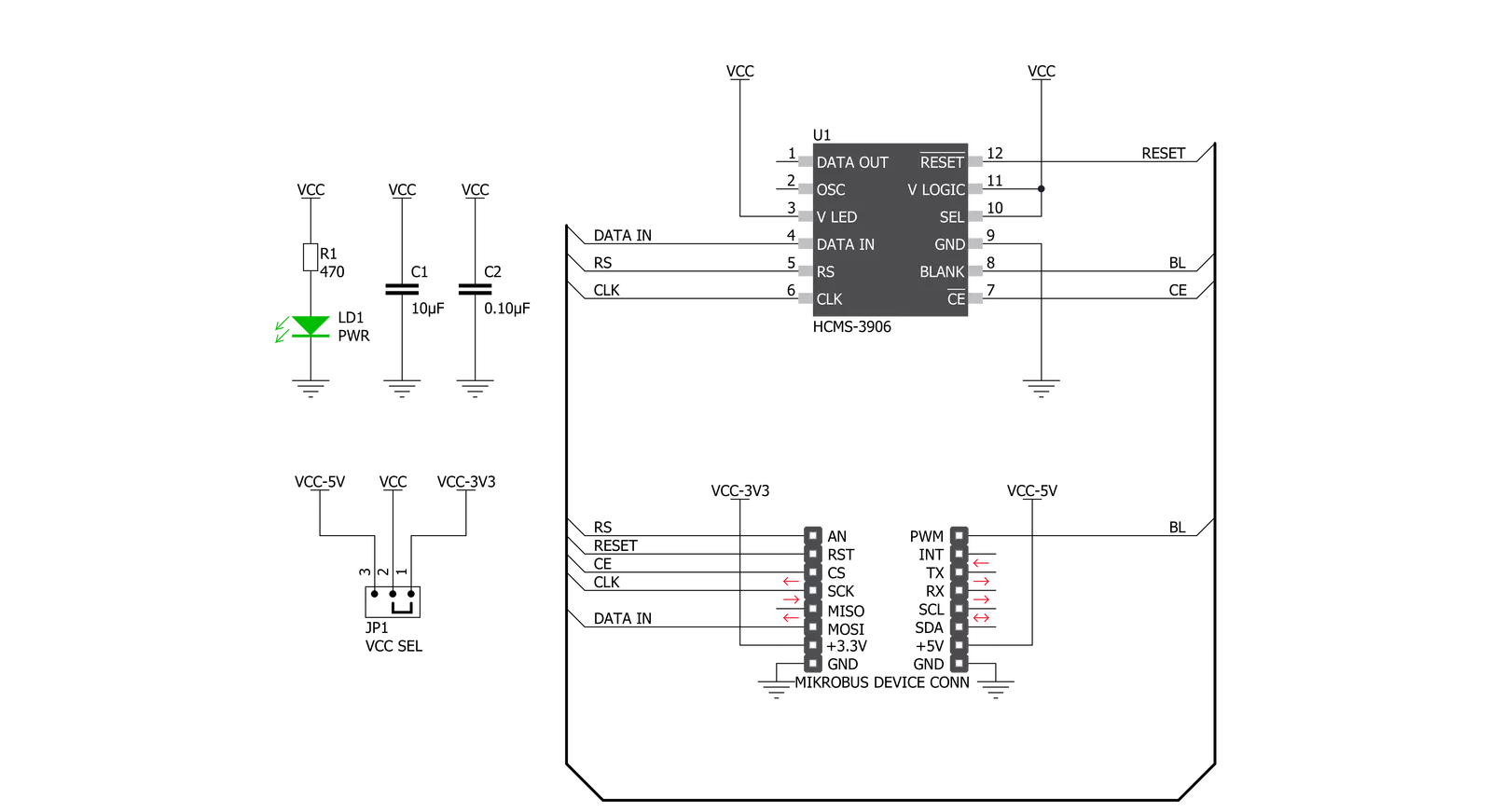
Dot Matrix R Click is based on the HCMS-3906, a four-digit dot matrix display module from Broadcom. Dot Matrix R Click is a high-performance, easy-to-use dot matrix display driven by an onboard CMOS IC. Each display can be directly interfaced with a microprocessor, thus eliminating the need for cumbersome interface components. The serial IC interface allows higher character count information displays with a minimum of data lines. The easy-to-read 5x7 pixel format allows the display of upper case, lower case, Katakana, and custom user-defined characters. These displays are stackable in the x- and y-directions, making them ideal for high character count displays. Typical applications include telecommunication equipment, portable data entry devices, computer peripherals, medical equipment, test equipment, business machines, avionics, industrial controls, and more. Featured LED display HCMS-3906 consists of LEDs configured as 5x7 font characters driven in groups of 4 characters per IC. Each IC comprises a 160-bit shift register (the Dot Register), two 7-bit Control Words, and refresh circuitry. The Dot Register contents are mapped on a one-to-one basis to the display. Thus, an individual Dot Register bit uniquely controls a single LED. Reset initializes the Control Registers (sets all Control Register bits to
logic low) and places the display in sleep mode. The Dot Registers are not cleared upon power-on or by Reset. After power-on, the Dot Register contents are random; however, Reset will put the display in sleep mode, thereby blanking the LEDs. The Control Register and the Control Words are cleared to all zeros by Reset. Load the Dot Register with logic lows to operate the display after being Reset. Then, load Control Word 0 with the desired brightness level and set the sleep mode bit to logic high. The Dot Register holds the pattern to be displayed by the LEDs. First, RS is brought low, then CE is brought low. Next, each successive rising CLK edge will shift the data at the DIN pin. Loading a logic high will turn the corresponding LED on; a logic low turns the LED off. When all 160 bits have been loaded, CE is brought to logic high. When CLK is next brought to logic low, new data is latched into the display dot drivers. Loading data into the Dot Register occurs while the previous data is displayed and eliminates the need to blank the display while loading data. In a 4-character display, the 160 bits are arranged as 20 columns by 8 rows. This array can be conceptualized as four 5x8 dot matrix character locations, but only 7 of the 8 rows have LEDs. The bottom row (row 0) is not used. Thus, latch location 0 is never displayed. Column 0 controls the left-most column.
Data from Dot Latch locations 0-7 determine whether or not pixels in Column 0 are turned on or off. Therefore, the lower left pixel is turned on when a logic high is stored in Dot Latch location 1. Characters are loaded serially, with the left-most character loaded first and the rightmost character loaded last. By loading one character at a time and latching the data before loading the next character, the figures will appear to scroll from right to left. The Control Register allows software modification of the IC’s operation and consists of two independent 7-bit control words. Bit D7 in the shift register selects one of the two 7-bit control words. Control Word 0 performs pulse width modulation, pixel map, brightness control, peak pixel current brightness control, and sleep mode. Control Word 1 sets serial/simultaneous data out mode and external oscillator prescaler. Each function is independent of the others. This Click board™ can operate with either 3.3V or 5V logic voltage levels selected via the VCC SEL jumper. This way, both 3.3V and 5V capable MCUs can use the communication lines properly. Also, this Click board™ comes equipped with a library containing easy-to-use functions and an example code that can be used as a reference for further development.


Features overview
Development board
PIC32MZ Clicker is a compact starter development board that brings the flexibility of add-on Click boards™ to your favorite microcontroller, making it a perfect starter kit for implementing your ideas. It comes with an onboard 32-bit PIC32MZ microcontroller with FPU from Microchip, a USB connector, LED indicators, buttons, a mikroProg connector, and a header for interfacing with external electronics. Thanks to its compact design with clear and easy-recognizable silkscreen markings, it provides a fluid and immersive working experience, allowing access anywhere and under
any circumstances. Each part of the PIC32MZ Clicker development kit contains the components necessary for the most efficient operation of the same board. In addition to the possibility of choosing the PIC32MZ Clicker programming method, using USB HID mikroBootloader, or through an external mikroProg connector for PIC, dsPIC, or PIC32 programmer, the Clicker board also includes a clean and regulated power supply module for the development kit. The USB Micro-B connection can provide up to 500mA of current, which is more than enough to operate all onboard
and additional modules. All communication methods that mikroBUS™ itself supports are on this board, including the well-established mikroBUS™ socket, reset button, and several buttons and LED indicators. PIC32MZ Clicker is an integral part of the Mikroe ecosystem, allowing you to create a new application in minutes. Natively supported by Mikroe software tools, it covers many aspects of prototyping thanks to a considerable number of different Click boards™ (over a thousand boards), the number of which is growing every day.

Microcontroller Overview
MCU Card / MCU

Architecture
PIC32
MCU Memory (KB)
1024
Silicon Vendor
Microchip
Pin count
64
RAM (Bytes)
524288
Used MCU Pins
mikroBUS™ mapper
Take a closer look
Click board™ Schematic
Step by step
Project assembly

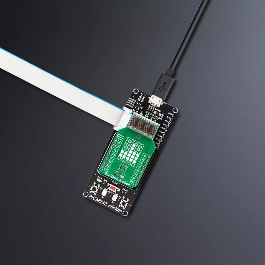
Start by selecting your development board and Click board™. Begin with the PIC32MZ clicker as your development board.


Software Support
Library Description
This library contains API for Dot Matrix R Click driver.
Key functions:
dotmatrixr_set_bl_pin_state- Sets BL pin to high or low statedotmatrixr_restart- Restart devicedotmatrixr_write_ascii- Sets display to written value
Open Source
Code example
The complete application code and a ready-to-use project are available through the NECTO Studio Package Manager for direct installation in the NECTO Studio. The application code can also be found on the MIKROE GitHub account.
/*!
 * \file
 * \brief DotMatrixR Click example
 *
 * # Description
 * This demo application show data on display.
 *
 * The demo application is composed of two sections :
 *
 * ## Application Init
 * Configuration device
 *
 * ## Application Task
 * Display shows 3 different data in span of 1 second
 *
 * \author MikroE Team
 *
 */
// ------------------------------------------------------------------- INCLUDES

#include "board.h"
#include "log.h"
#include "dotmatrixr.h"

// ------------------------------------------------------------------ VARIABLES

static dotmatrixr_t dotmatrixr;
static log_t logger;

char demo_t1[ 6 ] = "####";
char demo_t2[ 6 ] = "____";
char demo_t3[ 6 ] = "DotR";

// ------------------------------------------------------ APPLICATION FUNCTIONS

void application_init ( void )
{
    log_cfg_t log_cfg;
    dotmatrixr_cfg_t cfg;

    /**
     * Logger initialization.
     * Default baud rate: 115200
     * Default log level: LOG_LEVEL_DEBUG
     * @note If USB_UART_RX and USB_UART_TX
     * are defined as HAL_PIN_NC, you will
     * need to define them manually for log to work.
     * See @b LOG_MAP_USB_UART macro definition for detailed explanation.
     */
    LOG_MAP_USB_UART( log_cfg );
    log_init( &logger, &log_cfg );
    log_info( &logger, "---- Application Init ----" );

    //  Click initialization.

    dotmatrixr_cfg_setup( &cfg );
    DOTMATRIXR_MAP_MIKROBUS( cfg, MIKROBUS_1 );
    dotmatrixr_init( &dotmatrixr, &cfg );

    Delay_ms ( 100 );
    dotmatrixr_restart( &dotmatrixr );
    Delay_ms ( 500 );

    dotmatrixr_set_bl_pin_state( &dotmatrixr, 0 );
    dotmatrixr_set_rs_pin_state( &dotmatrixr, 0 );

    dotmatrixr_ctrl_1( &dotmatrixr, DOTMATRIXR_CTRL_BYTE_1_OSC_PRESCALER_1 |
                       DOTMATRIXR_CTRL_BYTE_1_DOUT_DIN );
    dotmatrixr_ctrl_0( &dotmatrixr, DOTMATRIXR_CTRL_BYTE_0_BRIGHTNESS_30 |
                       DOTMATRIXR_CTRL_BYTE_0_PIXEL_PEAK_CURRENT_9p3mA |
                       DOTMATRIXR_CTRL_BYTE_0_MODE_NORMAL );
}

void application_task ( void )
{
    dotmatrixr_write_ascii( &dotmatrixr, &demo_t1[ 0 ] );
    Delay_ms ( 1000 );
    dotmatrixr_write_ascii( &dotmatrixr, &demo_t2[ 0 ] );
    Delay_ms ( 1000 );
    dotmatrixr_write_ascii( &dotmatrixr, &demo_t3[ 0 ] );
    Delay_ms ( 1000 );
}

int main ( void )
{
    /* Do not remove this line or clock might not be set correctly. */
    #ifdef PREINIT_SUPPORTED
    preinit();
    #endif

    application_init( );

    for ( ; ; )
    {
        application_task( );
    }

    return 0;
}

// ------------------------------------------------------------------------ END
Additional Support
Resources
Category:LED Matrix


