Enhance any setting or project with its radiant glow using LP5862 and PIC18F4585
Dazzle and delight with a mesmerizing yellow

Published Nov 01, 2023
Click board™
LED Ring 2 Click
Dev. board
EasyPIC v8
Compiler
NECTO Studio
MCU
PIC18F4585
Discover the endless lighting possibilities with our circular yellow LED ring, designed to bring brilliance to a wide range of applications
A
A
Hardware Overview
How does it work?
LED Ring 2 Click is based on the LP5862, a high-performance LED matrix driver from Texas Instruments. The LP5862 integrates 18 constant current sinks for driving 18 LEDs. A standard yellow LED is used as a light source, the SML-LX0402SYC-TR, with a peak wavelength of 590nm. With the help of two additional LP5862 drivers, it is realized, as shown on this board, an LED ring of 54 yellow LEDs arranged in a circular pattern. This Click board™ can significantly improve user experience in various animation and indication application areas like smart home, gaming equipment, and other human-machine interaction applications. This Click board™ communicates with an MCU using the standard I2C 2-Wire interface to read
data and configure settings, supporting Fast-Plus mode with a frequency of up to 1MHz. The LP5862 also supports the register-configurable PWM dimming method for efficiently adjusting LED light brightness. For PWM dimming, the integrated 8-bit or 16-bit configurable, >20kHz PWM generators for each LED enable smooth, vivid animation effects without audible noise. Each LED can also be mapped into an 8-bit group PWM to achieve group control with minimum data traffic. The VSY pin of the mikroBUS™ socket serves as a synchronization signal. The LP5862 also implements full addressable SRAM, supporting entire SRAM data refresh and partial SRAM data update on demand to minimize the data traffic.
Besides, the LP5862 implements the ghost cancellation circuit to eliminate upside and downside ghosting. This Click board™ can operate with either 3.3V or 5V logic voltage levels selected via the VCC SEL jumper. This way, both 3.3V and 5V capable MCUs can use the communication lines properly. In addition, it is possible to select the LED supply voltage between either 3.3V or 5V voltage level set via the VLED SEL jumper. However, the Click board™ comes equipped with a library containing easy-to-use functions and an example code that can be used as a reference for further development.


Features overview
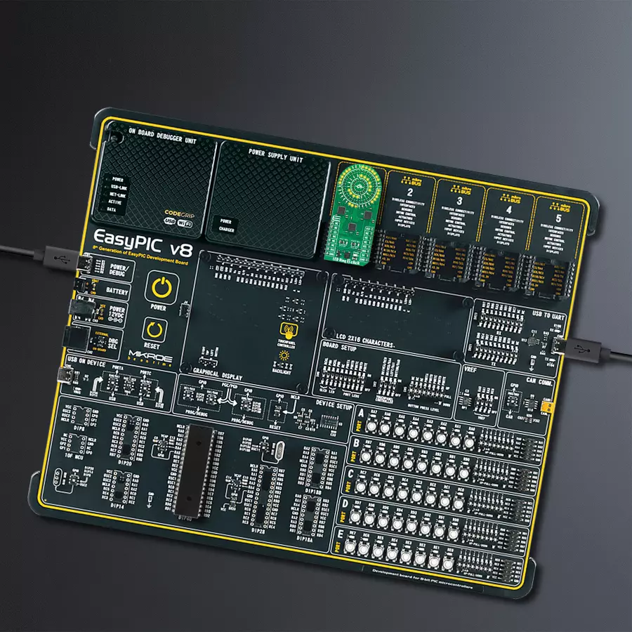
Development board
EasyPIC v8 is a development board specially designed for the needs of rapid development of embedded applications. It supports many high pin count 8-bit PIC microcontrollers from Microchip, regardless of their number of pins, and a broad set of unique functions, such as the first-ever embedded debugger/programmer. The development board is well organized and designed so that the end-user has all the necessary elements, such as switches, buttons, indicators, connectors, and others, in one place. Thanks to innovative manufacturing technology, EasyPIC v8 provides a fluid and immersive working experience, allowing access anywhere and under any
circumstances at any time. Each part of the EasyPIC v8 development board contains the components necessary for the most efficient operation of the same board. In addition to the advanced integrated CODEGRIP programmer/debugger module, which offers many valuable programming/debugging options and seamless integration with the Mikroe software environment, the board also includes a clean and regulated power supply module for the development board. It can use a wide range of external power sources, including a battery, an external 12V power supply, and a power source via the USB Type-C (USB-C) connector.
Communication options such as USB-UART, USB DEVICE, and CAN are also included, including the well-established mikroBUS™ standard, two display options (graphical and character-based LCD), and several different DIP sockets. These sockets cover a wide range of 8-bit PIC MCUs, from the smallest PIC MCU devices with only eight up to forty pins. EasyPIC v8 is an integral part of the Mikroe ecosystem for rapid development. Natively supported by Mikroe software tools, it covers many aspects of prototyping and development thanks to a considerable number of different Click boards™ (over a thousand boards), the number of which is growing every day.

Microcontroller Overview
MCU Card / MCU
Architecture
PIC
MCU Memory (KB)
48
Silicon Vendor
Microchip
Pin count
40
RAM (Bytes)
3328
Used MCU Pins
mikroBUS™ mapper
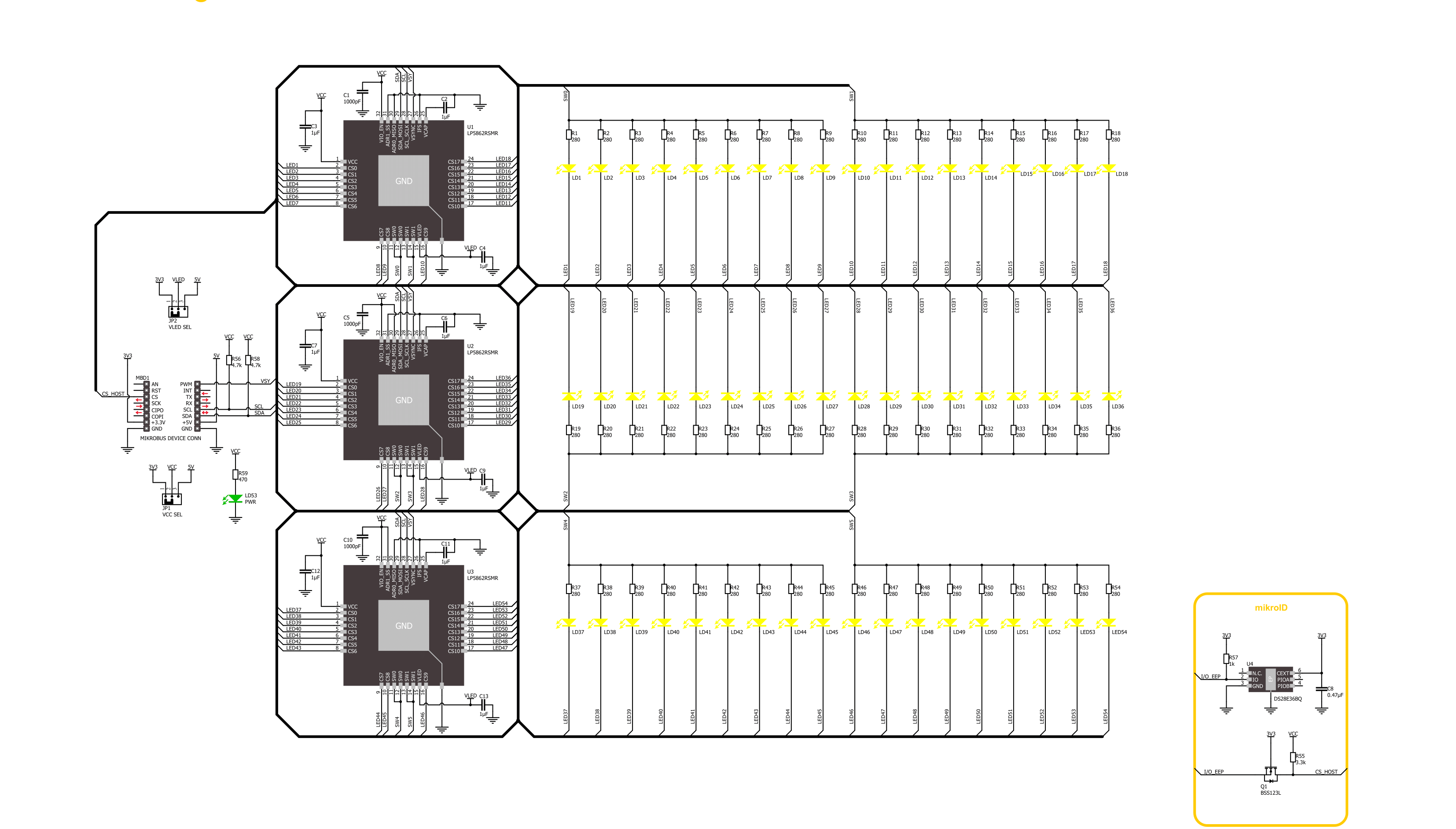
Take a closer look
Click board™ Schematic
Step by step
Project assembly

Start by selecting your development board and Click board™. Begin with the EasyPIC v8 as your development board.


Software Support
Library Description
This library contains API for LED Ring 2 Click driver.
Key functions:
ledring2_set_led_brightness- LED Ring 2 set LED brightness functionledring2_set_led_pos_state- LED Ring 2 set LED state functionledring2_enable- LED Ring 2 enable function
Open Source
Code example
The complete application code and a ready-to-use project are available through the NECTO Studio Package Manager for direct installation in the NECTO Studio. The application code can also be found on the MIKROE GitHub account.
/*!
 * @file main.c
 * @brief LED Ring 2 Click example
 *
 * # Description
 * This library contains API for LED Ring 2 Click driver.
 * The library initializes and defines the I2C bus drivers
 * to write and read data from registers.
 * The library also includes a function for controlling LEDs.
 *
 * The demo application is composed of two sections :
 *
 * ## Application Init
 * The initialization of I2C module, log UART, and additional pins.
 * After the driver init, the app executes a default configuration.
 *
 * ## Application Task
 * This example demonstrates the use of the LED Ring 2 Click board™.
 * The demo example controls every LED and changes the LED brightness by PWM,
 * increasing its brightness from LED1 to LED54.
 *
 * @author Nenad Filipovic
 *
 */

#include "board.h"
#include "log.h"
#include "ledring2.h"

static ledring2_t ledring2;
static log_t logger;

void application_init ( void )
{
    log_cfg_t log_cfg;  /**< Logger config object. */
    ledring2_cfg_t ledring2_cfg;  /**< Click config object. */

    /**
     * Logger initialization.
     * Default baud rate: 115200
     * Default log level: LOG_LEVEL_DEBUG
     * @note If USB_UART_RX and USB_UART_TX
     * are defined as HAL_PIN_NC, you will
     * need to define them manually for log to work.
     * See @b LOG_MAP_USB_UART macro definition for detailed explanation.
     */
    LOG_MAP_USB_UART( log_cfg );
    log_init( &logger, &log_cfg );
    log_info( &logger, " Application Init " );

    // Click initialization.
    ledring2_cfg_setup( &ledring2_cfg );
    LEDRING2_MAP_MIKROBUS( ledring2_cfg, MIKROBUS_1 );
    if ( I2C_MASTER_ERROR == ledring2_init( &ledring2, &ledring2_cfg ) )
    {
        log_error( &logger, " Communication init." );
        for ( ; ; );
    }
    Delay_ms ( 100 );

    if ( LEDRING2_ERROR == ledring2_default_cfg ( &ledring2 ) )
    {
        log_error( &logger, " Default configuration." );
        for ( ; ; );
    }
    Delay_ms ( 100 );
    log_info( &logger, " Application Task " );
    log_printf( &logger, " LED Ring 2 Click\r\n" );
}

void application_task ( void )
{
    for ( uint8_t led_pos = 1; led_pos < 55; led_pos++ )
    {
        if ( LEDRING2_OK == ledring2_set_led_brightness( &ledring2, led_pos, ( led_pos * 100 ) + 255 ) )
        {
            ledring2_set_vsync( &ledring2 );
            Delay_ms ( 10 );
        }
    }
    Delay_ms ( 1000 );

    for ( uint8_t led_pos = 54; led_pos > 0; led_pos-- )
    {
        if ( LEDRING2_OK == ledring2_set_led_brightness( &ledring2, led_pos, 0 ) )
        {
            ledring2_set_vsync( &ledring2 );
            Delay_ms ( 10 );
        }
    }
    Delay_ms ( 1000 );
}

int main ( void )
{
    /* Do not remove this line or clock might not be set correctly. */
    #ifdef PREINIT_SUPPORTED
    preinit();
    #endif

    application_init( );

    for ( ; ; )
    {
        application_task( );
    }

    return 0;
}

// ------------------------------------------------------------------------ END


