Make a unique navigation solution with L80 and TM4C129ENCZAD
Easily chart your course with utmost simplicity

Published Jun 21, 2023
Click board™
GPS3 Click
Dev. board
Fusion for Tiva v8
Compiler
NECTO Studio
MCU
TM4C129ENCZAD
Unleash the boundless potential of navigation technology, revolutionizing the way people explore and navigate
A
A
Hardware Overview
How does it work?
GPS3 Click is based on the L80, a GPS receiver module with a patch antenna equipped with an MTK positioning engine from Quectel. With an embedded LNA at a nominal frequency of 1575.42MHz, the L80 receives an L1 band signal from the GPS satellites. This module uses 66 search channels and 22 simultaneous tracking channels, making it possible to track and find satellites within the shortest time, even when the signal is in a signal-challenging environment. The embedded flash memory stores useful navigation data and performs updates. The L80 communicates with the host MUC using the UART interface with commonly used UART RX and TX
pins as its communication protocol operating at 9600bps. In addition, there is an RST pin for resetting the device. The GPS 3 Click also features a VBAT connector for connecting a battery for the RTC domain, which helps lower the power consumption. Regarding battery usage, the VCC-BCKP solder jumper should be removed. While the current date and time are transmitted in NMEA sentences (UTC), a precise and accurate timing signal is provided and indicated using a red LED indicator marked as PPS. The GPS 3 Click also features the u.FL connector for connecting the appropriate active antenna offered by MIKROE for improved range and received signal strength.
The antenna detection and switching functions will handle the connecting source without a hassle while keeping positioning. The detection result, notification, and statuses of the antennas will also be included in the NMEA message. This Click board™ can only be operated from a 3.3V logic voltage level. Therefore, the board must perform appropriate logic voltage conversion before using MCUs with different logic levels. However, the Click board™ comes equipped with a library containing functions and an example code that can be used as a reference for further development.

Features overview
Development board
Fusion for TIVA v8 is a development board specially designed for the needs of rapid development of embedded applications. It supports a wide range of microcontrollers, such as different 32-bit ARM® Cortex®-M based MCUs from Texas Instruments, regardless of their number of pins, and a broad set of unique functions, such as the first-ever embedded debugger/programmer over a WiFi network. The development board is well organized and designed so that the end-user has all the necessary elements, such as switches, buttons, indicators, connectors, and others, in one place. Thanks to innovative manufacturing technology, Fusion for TIVA v8 provides a fluid and immersive working experience, allowing access
anywhere and under any circumstances at any time. Each part of the Fusion for TIVA v8 development board contains the components necessary for the most efficient operation of the same board. An advanced integrated CODEGRIP programmer/debugger module offers many valuable programming/debugging options, including support for JTAG, SWD, and SWO Trace (Single Wire Output)), and seamless integration with the Mikroe software environment. Besides, it also includes a clean and regulated power supply module for the development board. It can use a wide range of external power sources, including a battery, an external 12V power supply, and a power source via the USB Type-C (USB-C) connector.
Communication options such as USB-UART, USB HOST/DEVICE, CAN (on the MCU card, if supported), and Ethernet is also included. In addition, it also has the well-established mikroBUS™ standard, a standardized socket for the MCU card (SiBRAIN standard), and two display options for the TFT board line of products and character-based LCD. Fusion for TIVA v8 is an integral part of the Mikroe ecosystem for rapid development. Natively supported by Mikroe software tools, it covers many aspects of prototyping and development thanks to a considerable number of different Click boards™ (over a thousand boards), the number of which is growing every day.

Microcontroller Overview
MCU Card / MCU
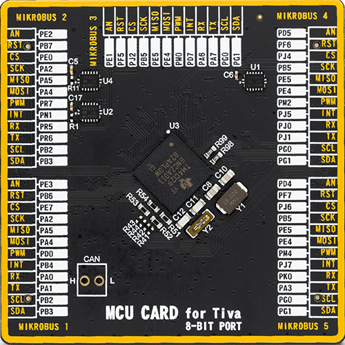
Type
8th Generation
Architecture
ARM Cortex-M4
MCU Memory (KB)
1024
Silicon Vendor
Texas Instruments
Pin count
212
RAM (Bytes)
262144
Used MCU Pins
mikroBUS™ mapper
Take a closer look
Click board™ Schematic

Step by step
Project assembly

Start by selecting your development board and Click board™. Begin with the Fusion for Tiva v8 as your development board.


Software Support
Library Description
This library contains API for GPS3 Click driver.
Key functions:
gps3_generic_read- This function reads a desired number of data bytes by using UART serial interfacegps3_clear_ring_buffers- This function clears UART TX and RX ring buffersgps3_parse_gpgga- This function parses the GPGGA data from the read response buffer
Open Source
Code example
The complete application code and a ready-to-use project are available through the NECTO Studio Package Manager for direct installation in the NECTO Studio. The application code can also be found on the MIKROE GitHub account.
/*!
 * @file main.c
 * @brief GPS 3 Click Example.
 *
 * # Description
 * This example demonstrates the use of GPS 3 Click by reading and displaying
 * the GPS coordinates.
 *
 * The demo application is composed of two sections :
 *
 * ## Application Init
 * Initializes the driver and logger.
 *
 * ## Application Task
 * Reads the received data, parses the GPGGA info from it, and once it receives the position fix
 * it will start displaying the coordinates on the USB UART.
 *
 * ## Additional Function
 * - static void gps3_clear_app_buf ( void )
 * - static err_t gps3_process ( gps3_t *ctx )
 * - static void gps3_parser_application ( char *rsp )
 *
 * @author Stefan Filipovic
 *
 */

#include "board.h"
#include "log.h"
#include "gps3.h"
#include "string.h"

#define PROCESS_BUFFER_SIZE 200

static gps3_t gps3;
static log_t logger;

static char app_buf[ PROCESS_BUFFER_SIZE ] = { 0 };
static int32_t app_buf_len = 0;

/**
 * @brief GPS 3 clearing application buffer.
 * @details This function clears memory of application buffer and reset its length.
 * @return None.
 * @note None.
 */
static void gps3_clear_app_buf ( void );

/**
 * @brief GPS 3 data reading function.
 * @details This function reads data from device and concatenates data to application buffer.
 * @param[in] ctx : Click context object.
 * See #gps3_t object definition for detailed explanation.
 * @return @li @c  0 - Read some data.
 *         @li @c -1 - Nothing is read.
 * See #err_t definition for detailed explanation.
 * @note None.
 */
static err_t gps3_process ( gps3_t *ctx );

/**
 * @brief GPS 3 parser application function.
 * @details This function parses GNSS data and logs it on the USB UART. It clears app and ring buffers
 * after successfully parsing data.
 * @param[in] ctx : Click context object.
 * See #gps3_t object definition for detailed explanation.
 * @param[in] rsp Response buffer.
 * @return None.
 * @note None.
 */
static void gps3_parser_application ( gps3_t *ctx, char *rsp );

void application_init ( void )
{
    log_cfg_t log_cfg;  /**< Logger config object. */
    gps3_cfg_t gps3_cfg;  /**< Click config object. */

    /**
     * Logger initialization.
     * Default baud rate: 115200
     * Default log level: LOG_LEVEL_DEBUG
     * @note If USB_UART_RX and USB_UART_TX
     * are defined as HAL_PIN_NC, you will
     * need to define them manually for log to work.
     * See @b LOG_MAP_USB_UART macro definition for detailed explanation.
     */
    LOG_MAP_USB_UART( log_cfg );
    log_init( &logger, &log_cfg );
    log_info( &logger, " Application Init " );

    // Click initialization.
    gps3_cfg_setup( &gps3_cfg );
    GPS3_MAP_MIKROBUS( gps3_cfg, MIKROBUS_1 );
    if ( UART_ERROR == gps3_init( &gps3, &gps3_cfg ) )
    {
        log_error( &logger, " Communication init." );
        for ( ; ; );
    }
    log_info( &logger, " Application Task " );
}

void application_task ( void )
{
    if ( GPS3_OK == gps3_process( &gps3 ) )
    {
        if ( PROCESS_BUFFER_SIZE == app_buf_len )
        {
            gps3_parser_application( &gps3, app_buf );
        }
    }
}

int main ( void )
{
    /* Do not remove this line or clock might not be set correctly. */
    #ifdef PREINIT_SUPPORTED
    preinit();
    #endif

    application_init( );

    for ( ; ; )
    {
        application_task( );
    }

    return 0;
}

static void gps3_clear_app_buf ( void )
{
    memset( app_buf, 0, app_buf_len );
    app_buf_len = 0;
}

static err_t gps3_process ( gps3_t *ctx )
{
    char rx_buf[ PROCESS_BUFFER_SIZE ] = { 0 };
    int32_t rx_size = 0;
    rx_size = gps3_generic_read( ctx, rx_buf, PROCESS_BUFFER_SIZE );
    if ( rx_size > 0 )
    {
        int32_t buf_cnt = app_buf_len;
        if ( ( ( app_buf_len + rx_size ) > PROCESS_BUFFER_SIZE ) && ( app_buf_len > 0 ) )
        {
            buf_cnt = PROCESS_BUFFER_SIZE - ( ( app_buf_len + rx_size ) - PROCESS_BUFFER_SIZE );
            memmove ( app_buf, &app_buf[ PROCESS_BUFFER_SIZE - buf_cnt ], buf_cnt );
        }
        for ( int32_t rx_cnt = 0; rx_cnt < rx_size; rx_cnt++ )
        {
            if ( rx_buf[ rx_cnt ] )
            {
                app_buf[ buf_cnt++ ] = rx_buf[ rx_cnt ];
                if ( app_buf_len < PROCESS_BUFFER_SIZE )
                {
                    app_buf_len++;
                }
            }
        }
        return GPS3_OK;
    }
    return GPS3_ERROR;
}

static void gps3_parser_application ( gps3_t *ctx, char *rsp )
{
    char element_buf[ 100 ] = { 0 };
    if ( GPS3_OK == gps3_parse_gpgga( rsp, GPS3_GPGGA_LATITUDE, element_buf ) )
    {
        static uint8_t wait_for_fix_cnt = 0;
        if ( strlen( element_buf ) > 0 )
        {
            log_printf( &logger, "\r\n Latitude: %.2s degrees, %s minutes \r\n", element_buf, &element_buf[ 2 ] );
            gps3_parse_gpgga( rsp, GPS3_GPGGA_LONGITUDE, element_buf );
            log_printf( &logger, " Longitude: %.3s degrees, %s minutes \r\n", element_buf, &element_buf[ 3 ] );
            memset( element_buf, 0, sizeof( element_buf ) );
            gps3_parse_gpgga( rsp, GPS3_GPGGA_ALTITUDE, element_buf );
            log_printf( &logger, " Altitude: %s m \r\n", element_buf );
            wait_for_fix_cnt = 0;
        }
        else
        {
            if ( wait_for_fix_cnt % 5 == 0 )
            {
                log_printf( &logger, " Waiting for the position fix...\r\n\n" );
                wait_for_fix_cnt = 0;
            }
            wait_for_fix_cnt++;
        }
        gps3_clear_ring_buffers( ctx );
        gps3_clear_app_buf( );
    }
}

// ------------------------------------------------------------------------ END
Additional Support
Resources
Category:GPS/GNSS


