Deliver data and control signals where you need them most thanks to the MAX41460 and TM4C129XKCZAD
Transmitting excellence, everywhere.

Published Nov 11, 2023
Click board™
ISM TX Click
Development board
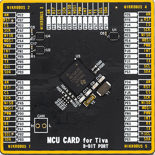
Fusion for Tiva v8
Compiler
NECTO Studio
MCU
TM4C129XKCZAD
Our ISM RF transmitter solution ensures excellence in wireless data transmission across a spectrum of industries, from IoT to remote monitoring.
A
A
Hardware Overview
How does it work?
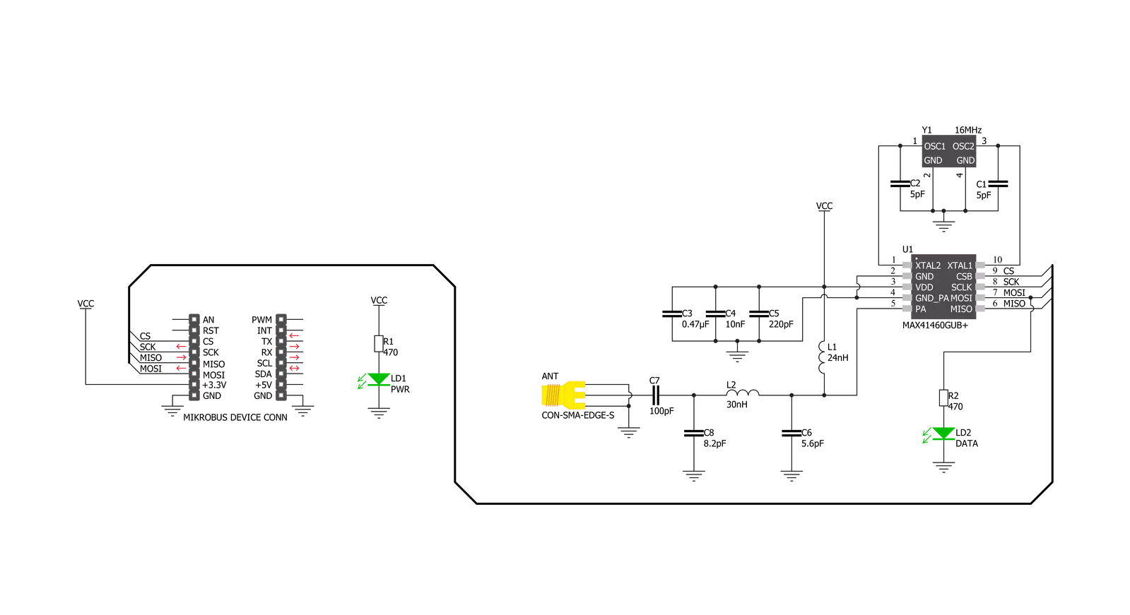
ISM TX Click is based on the MAX41460, a UHF sub-GHz ISM/SRD transmitter designed to transmit On-Off Keying (OOK), Amplitude- Shift Keying (ASK), Frequency-Shift Keying (FSK), and Gaussian (G)FSK (or 2GFSK) data from Analog Devices. The crystal-based architecture of the MAX41460 provides greater modulation depth, faster frequency settling, higher tolerance of the transmit frequency, and reduced temperature dependence. It integrates a fractional phase-locked loop (PLL), so a single, low-cost crystal of 16MHz used on this Click board™ can generate commonly used worldwide sub-GHz frequencies. A buffered clock-out signal makes the device compatible with almost any MCU or code-hopping generator. The MAX41460 features a fast oscillator Wake-Up upon data activity detection and has an Auto-Shutdown feature to extend battery life. This Click board™ has four major operating states: Shutdown, Stand-By, Programming,
and Transmitter-Enabled Mode. These states describe the Power-ON/Power-OFF status of the transmitter's three primary internal circuit blocks: the crystal oscillator (XO), the PLL synthesizer, and a high-efficiency, open-drain switching-mode power amplifier (PA). To ensure the MAX41460 enters the shutdown state after Power-On, the DATA pin must be held low at Power-On. The PA pin is used to adjust the frequency with only frequency-dependent components required for the external antenna-matching network that are connected so that the frequency of this Click board™ is fixed to 433.92MHz. The MAX41460 communicates with MCU using the standard SPI serial interface with a maximum frequency of 20 MHz. The device can support two types of SPI transactions: register access only and register access, followed by data transmission. In both Shutdown and Stand-By states, programming through the SPI interface is not allowed.
Configuration register values are retained in all states unless changed by programming or if the device is powered off. This Click board™, alongside the power LED indicator, has an additional green LED indicator labeled as DATA used to visually indicate the successful transmission of data across the SPI interface. ISM TX Click possesses the SMA antenna connector, and it can be used for connecting the appropriate antenna that MIKROE has in its offer, such as Rubber Antenna GSM/GPRS Right Angle. This antenna is an excellent choice for all GSM/GPRS applications and supports a range of frequencies and bands. This Click board™ can be operated only with a 3.3V logic voltage level. The board must perform appropriate logic voltage level conversion before using MCUs with different logic levels. Also, it comes equipped with a library containing functions and an example code that can be used as a reference for further development.

Features overview
Development board
Fusion for TIVA v8 is a development board specially designed for the needs of rapid development of embedded applications. It supports a wide range of microcontrollers, such as different 32-bit ARM® Cortex®-M based MCUs from Texas Instruments, regardless of their number of pins, and a broad set of unique functions, such as the first-ever embedded debugger/programmer over a WiFi network. The development board is well organized and designed so that the end-user has all the necessary elements, such as switches, buttons, indicators, connectors, and others, in one place. Thanks to innovative manufacturing technology, Fusion for TIVA v8 provides a fluid and immersive working experience, allowing access
anywhere and under any circumstances at any time. Each part of the Fusion for TIVA v8 development board contains the components necessary for the most efficient operation of the same board. An advanced integrated CODEGRIP programmer/debugger module offers many valuable programming/debugging options, including support for JTAG, SWD, and SWO Trace (Single Wire Output)), and seamless integration with the Mikroe software environment. Besides, it also includes a clean and regulated power supply module for the development board. It can use a wide range of external power sources, including a battery, an external 12V power supply, and a power source via the USB Type-C (USB-C) connector.
Communication options such as USB-UART, USB HOST/DEVICE, CAN (on the MCU card, if supported), and Ethernet is also included. In addition, it also has the well-established mikroBUS™ standard, a standardized socket for the MCU card (SiBRAIN standard), and two display options for the TFT board line of products and character-based LCD. Fusion for TIVA v8 is an integral part of the Mikroe ecosystem for rapid development. Natively supported by Mikroe software tools, it covers many aspects of prototyping and development thanks to a considerable number of different Click boards™ (over a thousand boards), the number of which is growing every day.

Microcontroller Overview
MCU Card / MCU
Type
8th Generation
Architecture
ARM Cortex-M4
MCU Memory (KB)
512
Silicon Vendor
Texas Instruments
Pin count
212
RAM (Bytes)
262144
You complete me!
Accessories
Right angle 433MHz rubber antenna boasts a frequency range of 433MHz, ensuring optimal performance within this spectrum. With a 50Ohm impedance, it facilitates efficient signal transmission. The antenna's vertical polarization enhances signal reception in a specific orientation. Featuring a 1.5dB gain, it can improve signal strength to some extent. The antenna can handle a maximum input power of 50W, making it suitable for various applications. Its compact 50mm length minimizes spatial requirements. Equipped with an SMA male connector, it easily interfaces with compatible devices. This antenna is an adaptable solution for wireless communication needs, particularly when vertical polarization is crucial.

868MHz right-angle rubber antenna is a compact and versatile solution for wireless communication. Operating within the frequency range of 868-915MHz, it ensures optimal signal reception and transmission. With a 50-ohm impedance, it's compatible with various devices and systems. This antenna boasts a 2dB gain, enhancing signal strength and extending communication range. Its vertical polarization further contributes to signal clarity. Designed to handle up to 50W of input power, it's a robust choice for various applications. Measuring just 48mm in length, this antenna is both discreet and practical. Its SMA male connector ensures a secure and reliable connection to your equipment. Whether you're working with IoT devices, remote sensors, or other wireless technologies, the 868MHz right-angle antenna offers the performance and flexibility you need for seamless communication.

Used MCU Pins
mikroBUS™ mapper
Take a closer look
Schematic
Step by step
Project assembly

Start by selecting your development board and Click board™. Begin with the Fusion for Tiva v8 as your development board.


Track your results in real time
Application Output
After pressing the "FLASH" button on the left-side panel, it is necessary to open the UART terminal to display the achieved results. By clicking on the Tools icon in the right-hand panel, multiple different functions are displayed, among which is the UART Terminal. Click on the offered "UART Terminal" icon.

Once the UART terminal is opened, the window takes on a new form. At the top of the tab are two buttons, one for adjusting the parameters of the UART terminal and the other for connecting the UART terminal. The tab's lower part is reserved for displaying the achieved results. Before connecting, the terminal has a Disconnected status, indicating that the terminal is not yet active. Before connecting, it is necessary to check the set parameters of the UART terminal. Click on the "OPTIONS" button.

In the newly opened UART Terminal Options field, we check if the terminal settings are correct, such as the set port and the Baud rate of UART communication. If the data is not displayed properly, it is possible that the Baud rate value is not set correctly and needs to be adjusted to 115200. If all the parameters are set correctly, click on "CONFIGURE".

The next step is to click on the "CONNECT" button, after which the terminal status changes from Disconnected to Connected in green, and the data is displayed in the Received data field.

Software Support
Library Description
This library contains API for ISM TX Click driver.
Key functions:
ismtx_set_cfg- ISM TX writing configuration.ismtx_set_frequency- Setting specific frequency for transmission.ismtx_transmit_data- Function for transmitting data with preamble byte and lenght.
Open Source
Code example
This example can be found in NECTO Studio. Feel free to download the code, or you can copy the code below.
/*!
 * @file main.c
 * @brief ISMTX Click example
 *
 * # Description
 * This application shows capability of ISM TX Click board.
 * It sets default configuration, and transmits data in
 * manchester encoding with FSK or ASK signal modulation.
 *
 * The demo application is composed of two sections :
 *
 * ## Application Init
 * Initialization of log and communication, set's signal modulation,
 * resets device, and set's default configuration for selected modulation.

 *
 * ## Application Task
 * Transmits data via external antenna in span of 500ms.
 *
 * *note:*
 * Default configuration configures device and set's transmission frequency to 433.92 MHz.
 * If selected modulation is FSK frequency deviation is set to 40kHz.
 *
 * @author Luka Filipovic
 *
 */

#include "board.h"
#include "log.h"
#include "ismtx.h"

#define PREAMBLE_BYTE   0xFF

#define TX_DATA         "MikroE"

static ismtx_t ismtx;
static log_t logger;


void application_init ( void )
{
    log_cfg_t log_cfg;      /**< Logger config object. */
    ismtx_cfg_t ismtx_cfg;  /**< Click config object. */

    /**
     * Logger initialization.
     * Default baud rate: 115200
     * Default log level: LOG_LEVEL_DEBUG
     * @note If USB_UART_RX and USB_UART_TX
     * are defined as HAL_PIN_NC, you will
     * need to define them manually for log to work.
     * See @b LOG_MAP_USB_UART macro definition for detailed explanation.
     */
    LOG_MAP_USB_UART( log_cfg );
    log_init( &logger, &log_cfg );
    log_info( &logger, " Application Init " );

    // Click initialization.
    ismtx_cfg_setup( &ismtx_cfg );
    ISMTX_MAP_MIKROBUS( ismtx_cfg, MIKROBUS_1 );
    err_t init_flag  = ismtx_init( &ismtx, &ismtx_cfg );
    if ( init_flag == SPI_MASTER_ERROR )
    {
        log_error( &logger, " Application Init Error. " );
        log_info( &logger, " Please, run program again... " );

        for ( ; ; );
    }

    ismtx.modulation = ISM_TX_MODULATION_FSK;

    ismtx_soft_reset( &ismtx );

    if ( ismtx_default_cfg ( &ismtx ) < 0 )
    {
        log_error( &logger, " Application Init Error. " );
        log_info( &logger, " Please, select correct signal modulation... " );

        for ( ; ; );
    }

    log_info( &logger, " Application Task " );
}

void application_task ( void )
{
    log_info( &logger, " Data sent! [%s]", TX_DATA );
    ismtx_transmit_data( &ismtx, PREAMBLE_BYTE, TX_DATA, strlen( TX_DATA ) );
    Delay_ms( 500 );
}

void main ( void )
{
    application_init( );

    for ( ; ; )
    {
        application_task( );
    }
}

// ------------------------------------------------------------------------ END


