Achieve precise power analysis with MCP39F511A and PIC18F87J11
Upgrade your U/I monitoring

Published Sep 30, 2023
Click board™
PWR Meter Click
Dev. board
UNI-DS v8
Compiler
NECTO Studio
MCU
PIC18F87J11
Our cutting-edge power monitoring solution excels at measuring and monitoring voltage and current values with exceptional precision, empowering you to optimize energy usage and ensure the reliability of your electrical systems
A
A
Hardware Overview
How does it work?
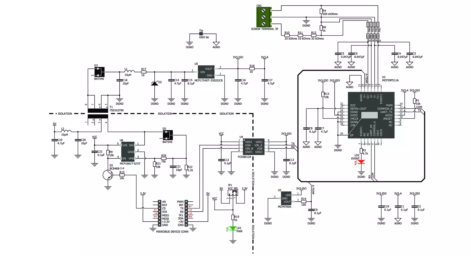
PWR Meter Click is based on the MCP39F511A, a power monitoring IC with on-chip 16-bit data processing and energy accumulation features from Microchip. This IC is an advanced power monitoring IC, capable of calculating power characteristics, based on the measurements taken from the connected load and power supply. The IC is able to calculate active, reactive, and apparent power, current and voltage RMS, line frequency, and power factor. In addition, it features several useful functions, such as the programmable event reporting, with the onboard LED labeled as the EVENT. PWR Meter click uses the UART interface for the communication with the host MCU. The communication is based on the SSI (Simple Sensor Interface) protocol and it is fairly simple to use. This protocol is widely used for a point-to-point communication between the host MCU and other sensor devices, such as the MCP39F511A. The default rate of the protocol is 9600 bps, but it can be configured by the user. More information about the communication protocol itself and the commands that can be used can be found in the MCP39F511A datasheet. However, PWR Meter click comes with a library which is compatible with all the MikroElektronika compilers. It contains functions which make working with the PWR Meter click even simpler, saving a lot of development time. The MCP39F511A incorporates two internal 24-bit Analog to Digital Converters (ADC), used to sample the voltage values on their differential inputs. One channel is used to
measure the voltage drop across the shunt resistor with the value of 0.2Ω, while the second channel samples the voltage across the voltage divider on the input terminal. The voltage drop across the shunt resistor allows calculating the current through the connected load, while the voltage divider allows voltage measurement across the connected load, scaling it down so that it can be measured. A third, 10-bit ADC is used to measure the ambient temperature, needed for compensation. It is connected to an output of the MCP9700A, a low power linear active integrated thermistor, from Microchip. The load should be connected to the 3-pole input terminal, between the input labeled with the L letter and the input labeled as the V-. The power supply should be also connected to the Click board™. Its hot (positive) end should be connected to the V+ labeled input of the 3-pole terminal, while the negative end should be connected to the input labeled as V-. The power supply should not exceed 50V. To better understand connection scheme, please take a look at the picture below. The Click board™ features a complete galvanic isolation of the measured circuit. The power for the high voltage section is provided by the MCP1661, an efficient, integrated boost (step-up) DC/DC converter, from Microchip. The integrated boost converter is built using the flyback topology, allowing a complete galvanic isolation between the primary and secondary side, since it uses a transformer instead of a coil. The input voltage of the DC-DC converter
is selected by an SMD jumper, labeled as the VCC SEL. The boosted voltage on the secondary of the transformer is further conditioned by the MCP17545, an LDO regulator from Microchip, and it is fixed to 3V. The output of the LDO is now galvanically isolated from the rest of the circuit, and it is used to supply the MCP39F511A monitoring IC and the additional thermal sensor with power. Turning on or off the MCP1661 DC/DC converter controls the operation of the PWR Meter click itself. The CS pin of the mikroBUS™ is routed to the EN pin of the MCP1661 converter, allowing the user to turn off the power for the monitoring IC. Setting the CS pin to a HIGH logic level will disable the converter, allowing current to sink through the transistor, thus setting the EN pin to a LOW logic level. Otherwise, the EN pin is pulled up to a HIGH level with the resistor, and the converter is enabled by default (when the CS pin of the mikroBUS™ is left floating, or driven to a LOW logic level) Galvanic isolation of the MCP39F511A data lines is done by using a bi-directional logic gate optocoupler, labeled as FOD8012A from ON Semiconductors. UART RX and TX lines from the MCP39F511A IC run through the integrated optocouplers and are also completely isolated from the low voltage circuitry. The previously mentioned VCC SEL jumper also selects the voltage for the optocoupler, allowing both 3.3V and 5V tolerant MCUs to be interfaced with the Click board™.

Features overview
Development board
UNI-DS v8 is a development board specially designed for the needs of rapid development of embedded applications. It supports a wide range of microcontrollers, such as different STM32, Kinetis, TIVA, CEC, MSP, PIC, dsPIC, PIC32, and AVR MCUs regardless of their number of pins, and a broad set of unique functions, such as the first-ever embedded debugger/programmer over WiFi. The development board is well organized and designed so that the end-user has all the necessary elements, such as switches, buttons, indicators, connectors, and others, in one place. Thanks to innovative manufacturing technology, UNI-DS v8 provides a fluid and immersive working experience, allowing access anywhere and under any
circumstances at any time. Each part of the UNI-DS v8 development board contains the components necessary for the most efficient operation of the same board. An advanced integrated CODEGRIP programmer/debugger module offers many valuable programming/debugging options, including support for JTAG, SWD, and SWO Trace (Single Wire Output)), and seamless integration with the Mikroe software environment. Besides, it also includes a clean and regulated power supply module for the development board. It can use a wide range of external power sources, including a battery, an external 12V power supply, and a power source via the USB Type-C (USB-C) connector. Communication options such as USB-UART, USB
HOST/DEVICE, CAN (on the MCU card, if supported), and Ethernet is also included. In addition, it also has the well-established mikroBUS™ standard, a standardized socket for the MCU card (SiBRAIN standard), and two display options for the TFT board line of products and character-based LCD. UNI-DS v8 is an integral part of the Mikroe ecosystem for rapid development. Natively supported by Mikroe software tools, it covers many aspects of prototyping and development thanks to a considerable number of different Click boards™ (over a thousand boards), the number of which is growing every day.

Microcontroller Overview
MCU Card / MCU
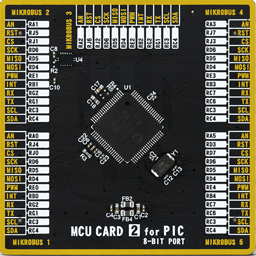
Type
8th Generation
Architecture
PIC
MCU Memory (KB)
128
Silicon Vendor
Microchip
Pin count
80
RAM (Bytes)
3904
Used MCU Pins
mikroBUS™ mapper
Take a closer look
Click board™ Schematic
Step by step
Project assembly

Start by selecting your development board and Click board™. Begin with the UNI-DS v8 as your development board.


Track your results in real time
Application Output
1. Application Output - In Debug mode, the 'Application Output' window enables real-time data monitoring, offering direct insight into execution results. Ensure proper data display by configuring the environment correctly using the provided tutorial.

2. UART Terminal - Use the UART Terminal to monitor data transmission via a USB to UART converter, allowing direct communication between the Click board™ and your development system. Configure the baud rate and other serial settings according to your project's requirements to ensure proper functionality. For step-by-step setup instructions, refer to the provided tutorial.

3. Plot Output - The Plot feature offers a powerful way to visualize real-time sensor data, enabling trend analysis, debugging, and comparison of multiple data points. To set it up correctly, follow the provided tutorial, which includes a step-by-step example of using the Plot feature to display Click board™ readings. To use the Plot feature in your code, use the function: plot(*insert_graph_name*, variable_name);. This is a general format, and it is up to the user to replace 'insert_graph_name' with the actual graph name and 'variable_name' with the parameter to be displayed.

Software Support
Library Description
This library contains API for PWR Meter Click driver.
Key functions:
pwrmeter_read_reg_word- Function reads 16-bit data from the desired registerpwrmeter_read_reg_dword- Function reads 32-bit data from the desired registerpwrmeter_read_reg_signed- Function reads signed 16bit or 32bit data from the desired register.
Open Source
Code example
The complete application code and a ready-to-use project are available through the NECTO Studio Package Manager for direct installation in the NECTO Studio. The application code can also be found on the MIKROE GitHub account.
/*!
* \file
* \brief PwrMeter2 Click example
*
* # Description
* This app measuring and monitoring voltage up to 24V and current up to 5A.
*
* The demo application is composed of two sections :
*
* ## Application Init
* Initializes device.
*
* ## Application Task
* Gets calculated voltage, current and power data every 500 milliseconds
* and shows results on UART.
*
* \author MikroE Team
*
*/
// ------------------------------------------------------------------- INCLUDES
#include "board.h"
#include "log.h"
#include "pwrmeter2.h"
// ------------------------------------------------------------------ VARIABLES
static pwrmeter2_t pwrmeter2;
static log_t logger;
// ------------------------------------------------------ APPLICATION FUNCTIONS
void application_init ( void )
{
log_cfg_t log_cfg; /**< Logger config object. */
pwrmeter2_cfg_t pwrmeter2_cfg; /**< Click config object. */
/**
* Logger initialization.
* Default baud rate: 115200
* Default log level: LOG_LEVEL_DEBUG
* @note If USB_UART_RX and USB_UART_TX
* are defined as HAL_PIN_NC, you will
* need to define them manually for log to work.
* See @b LOG_MAP_USB_UART macro definition for detailed explanation.
*/
LOG_MAP_USB_UART( log_cfg );
log_init( &logger, &log_cfg );
log_info( &logger, " Application Init " );
// Click initialization.
pwrmeter2_cfg_setup( &pwrmeter2_cfg );
PWRMETER2_MAP_MIKROBUS( pwrmeter2_cfg, MIKROBUS_1 );
if ( SPI_MASTER_ERROR == pwrmeter2_init( &pwrmeter2, &pwrmeter2_cfg ) )
{
log_error( &logger, " Communication init." );
for ( ; ; );
}
if ( PWRMETER2_ERROR == pwrmeter2_default_cfg ( &pwrmeter2 ) )
{
log_error( &logger, " Default configuration." );
for ( ; ; );
}
log_info( &logger, " Application Task " );
}
void application_task ( void )
{
float voltage = 0;
float current = 0;
float power = 0;
if ( PWRMETER2_OK == pwrmeter2_get_data( &pwrmeter2, &voltage, ¤t, &power ) )
{
log_printf( &logger, " U = %.3f V\r\n", voltage );
log_printf( &logger, " I = %.3f A\r\n", current );
log_printf( &logger, " P = %.3f W\r\n\n", power );
Delay_ms ( 500 );
}
}
int main ( void )
{
/* Do not remove this line or clock might not be set correctly. */
#ifdef PREINIT_SUPPORTED
preinit();
#endif
application_init( );
for ( ; ; )
{
application_task( );
}
return 0;
}
// ------------------------------------------------------------------------ END


