Stay on schedule with MCP79410 and PIC32MX795F512L
Mastering time: The unseen wonders of RTC

Published Oct 20, 2023
Click board™
RTC 6 Click
Dev. board
UNI-DS v8
Compiler
NECTO Studio
MCU
PIC32MX795F512L
Take control of time synchronization in your projects with advanced real-time clock, delivering reliable and precise timing accuracy
A
A
Hardware Overview
How does it work?
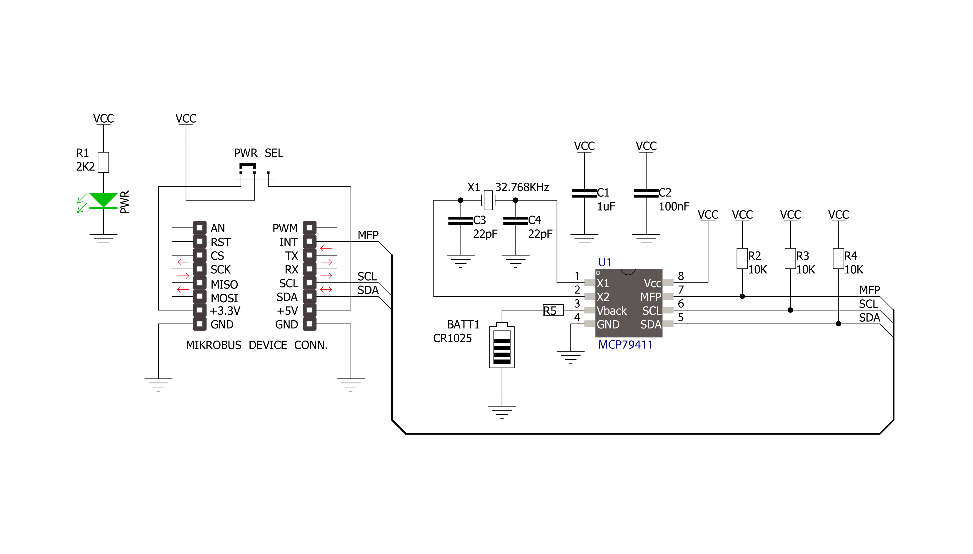
RTC 6 Click is based on the MCP79411, a battery-backed I2C real-time clock/calendar with SRAM, and protected EEPROM from Microchip. The alarms on this RTC 6 Click can be configured on all counters up to and including months. The clock frequency is delivered from an onboard 32.768KHz crystal oscillator. On-chip digital trimming with ±1 ppm resolution and ±129 ppm range can be used to adjust for frequency variance caused by crystal tolerance and temperature. For backup power for the RTC, this Click board™ features the coin-cell Lithium battery holder that supports CR1216, CR1220, and CR1225 battery formats. By removing the 0ohm resistor, you can turn off battery backup. For storing data, the MCP79411 has 64 bytes of battery-backed SRAM that correlate with the
timekeeping circuit and allow the device to maintain accurate time and date when main power is lost. The time between power switches, from backup to primary power and vice versa, is restored is recorded by the power outage time stamp. The MCP79411 features 1Kbit of internal nonvolatile EEPROM with software write protectable regions. An additional 64 bits of protected nonvolatile memory is only writable after an unlock sequence, making it ideal for storing a unique ID or other critical information. The RTC 6 Click uses an I2C interface for communication with the host MCU, with a clock rate of up to 400kHz. This Click board™ also features a multifunction pin, accessible over the MFP pin of the mikroBUS™ socket. The
multifunctional output on this pin can be configured to assert an alarm match to output a selectable frequency square wave or as a general-purpose output. The MCP79411 features two independent alarms. Each alarm can generate either an interrupt at a specific time in the future or a periodic interrupt every minute, hour, day, day of week, or month. This Click board™ can operate with either 3.3V or 5V logic voltage levels selected via the PWR SEL jumper. This way, both 3.3V and 5V capable MCUs can use the communication lines properly. Also, this Click board™ comes equipped with a library containing easy-to-use functions and an example code that can be used as a reference for further development.

Features overview
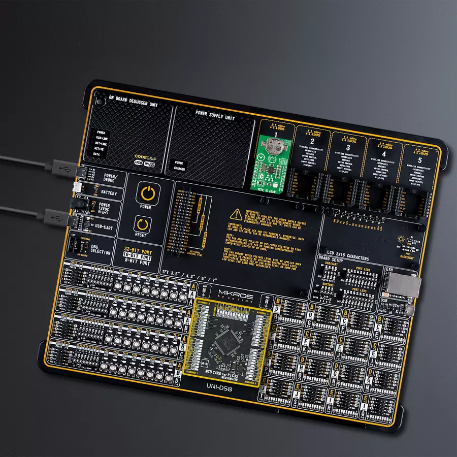
Development board
UNI-DS v8 is a development board specially designed for the needs of rapid development of embedded applications. It supports a wide range of microcontrollers, such as different STM32, Kinetis, TIVA, CEC, MSP, PIC, dsPIC, PIC32, and AVR MCUs regardless of their number of pins, and a broad set of unique functions, such as the first-ever embedded debugger/programmer over WiFi. The development board is well organized and designed so that the end-user has all the necessary elements, such as switches, buttons, indicators, connectors, and others, in one place. Thanks to innovative manufacturing technology, UNI-DS v8 provides a fluid and immersive working experience, allowing access anywhere and under any
circumstances at any time. Each part of the UNI-DS v8 development board contains the components necessary for the most efficient operation of the same board. An advanced integrated CODEGRIP programmer/debugger module offers many valuable programming/debugging options, including support for JTAG, SWD, and SWO Trace (Single Wire Output)), and seamless integration with the Mikroe software environment. Besides, it also includes a clean and regulated power supply module for the development board. It can use a wide range of external power sources, including a battery, an external 12V power supply, and a power source via the USB Type-C (USB-C) connector. Communication options such as USB-UART, USB
HOST/DEVICE, CAN (on the MCU card, if supported), and Ethernet is also included. In addition, it also has the well-established mikroBUS™ standard, a standardized socket for the MCU card (SiBRAIN standard), and two display options for the TFT board line of products and character-based LCD. UNI-DS v8 is an integral part of the Mikroe ecosystem for rapid development. Natively supported by Mikroe software tools, it covers many aspects of prototyping and development thanks to a considerable number of different Click boards™ (over a thousand boards), the number of which is growing every day.

Microcontroller Overview
MCU Card / MCU
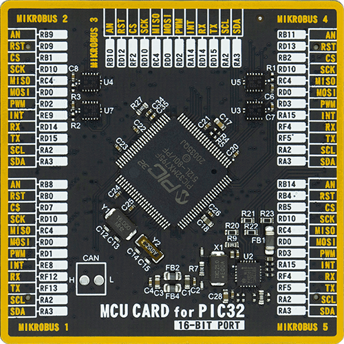
Type
8th Generation
Architecture
PIC32
MCU Memory (KB)
512
Silicon Vendor
Microchip
Pin count
100
RAM (Bytes)
131072
Used MCU Pins
mikroBUS™ mapper
Take a closer look
Click board™ Schematic
Step by step
Project assembly

Start by selecting your development board and Click board™. Begin with the UNI-DS v8 as your development board.


Software Support
Library Description
This library contains API for RTC 6 Click driver.
Key functions:
rtc6_battery_enable- This function enables automatic switch to battery on VCC failurertc6_get_gmt_time- This function gets current GMT time and sets it in the RTCrtc6_get_local_time- This function calculates current local time
Open Source
Code example
The complete application code and a ready-to-use project are available through the NECTO Studio Package Manager for direct installation in the NECTO Studio. The application code can also be found on the MIKROE GitHub account.
/*!
 * \file
 * \brief Rtc2 Click example
 *
 * # Description
 * This application give time and date information.
 *
 * The demo application is composed of two sections :
 *
 * ## Application Init
 *  Initialization driver enable's - I2C,set start time and date, enable counting and start write log.
 *
 * ## Application Task
 * This is a example which demonstrates the use of RTC 2 Click board.
 *    RTC 2 Click communicates with register via I2C by write to register and read from register,
 *    set time and date, get time and date, enable and disable counting
 *    and set frequency by write configuration register.
 *    Results are being sent to the Usart Terminal where you can track their changes.
 *    All data logs write on usb uart changes for every 1 sec.
 *
 * *note:*
 * Additional Functions :
 *
 * - void displayDayOfTheWeek( uint8_t dayOfTheWeek ) - Write day of the week log on USART terminal.
 * - void displayLogUart( uint8_t value ) - Write the value ( time or date ) of a two-digit number.
 *
 * \author MikroE Team
 *
 */
// ------------------------------------------------------------------- INCLUDES

#include "board.h"
#include "log.h"
#include "rtc2.h"

// ------------------------------------------------------------------ VARIABLES

static rtc2_t rtc2;
static log_t logger;
static rtc2_data_t date;

uint8_t time_hours;
uint8_t time_minutes;
uint8_t time_seconds;
uint8_t day_of_the_week;
uint8_t date_day;
uint8_t date_month;
uint16_t date_year;
uint8_t time_seconds_new = 0;

void display_day_of_the_week ( uint8_t day_of_the_week )
{
    if ( day_of_the_week == 1 )
    {
        log_printf( &logger, "      Monday      " );
    }
    if ( day_of_the_week == 2 )
    {
        log_printf( &logger, "      Tuesday     " );
    }
    if ( day_of_the_week == 3 )
    {
        log_printf( &logger, "     Wednesday    " );
    }
    if ( day_of_the_week == 4 )
    {
        log_printf( &logger, "     Thursday     " );
    }
    if ( day_of_the_week == 5 )
    {
        log_printf( &logger, "      Friday      " );
    }
    if ( day_of_the_week == 6 )
    {
        log_printf( &logger, "     Saturday     " );
    }
    if ( day_of_the_week == 7 )
    {
        log_printf( &logger, "      Sunday      " );
    }
}

void display_log_uart ( uint8_t value )
{

    log_printf( &logger,"%u", ( uint16_t )( value / 10 ) );

    log_printf( &logger,"%u", ( uint16_t )( value % 10 ) );
}


void application_init ( void )
{
    log_cfg_t log_cfg;
    rtc2_cfg_t cfg;

    date.day_of_the_week = 1;
    date.date_day = 31;
    date.date_month = 12;
    date.date_year = 2018;

    /**
     * Logger initialization.
     * Default baud rate: 115200
     * Default log level: LOG_LEVEL_DEBUG
     * @note If USB_UART_RX and USB_UART_TX
     * are defined as HAL_PIN_NC, you will
     * need to define them manually for log to work.
     * See @b LOG_MAP_USB_UART macro definition for detailed explanation.
     */
    LOG_MAP_USB_UART( log_cfg );
    log_init( &logger, &log_cfg );
    log_info( &logger, "---- Application Init ----" );

    //  Click initialization.

    rtc2_cfg_setup( &cfg );
    RTC2_MAP_MIKROBUS( cfg, MIKROBUS_1 );
    rtc2_init( &rtc2, &cfg );

    rtc2_set_time( &rtc2, 23, 59, 50 );
    rtc2_set_date( &rtc2, &date );
    rtc2_enable_counting( &rtc2 );
}

void application_task ( void )
{
    rtc2_get_time( &rtc2, &time_hours, &time_minutes, &time_seconds );

    rtc2_get_date( &rtc2, &date );

    if ( time_seconds_new !=  time_seconds )
    {
        log_printf( &logger, " Time : " );

        display_log_uart( time_hours );
        log_printf( &logger, ":" );

        display_log_uart( time_minutes );
        log_printf( &logger, ":" );

        display_log_uart( time_seconds );
        log_printf( &logger, "" );

        display_day_of_the_week( date.day_of_the_week );

        log_printf( &logger, " Date: " );

        display_log_uart( date.date_day );
        log_printf( &logger, "." );

        display_log_uart( date.date_month );
        log_printf( &logger, "." );

        log_printf( &logger, "20" );

        display_log_uart( date.date_year );
        log_printf( &logger, ".\r\n" );

        log_printf( &logger, "-------------------\r\n" );

        time_seconds_new =  time_seconds;
    }
}

int main ( void )
{
    /* Do not remove this line or clock might not be set correctly. */
    #ifdef PREINIT_SUPPORTED
    preinit();
    #endif

    application_init( );

    for ( ; ; )
    {
        application_task( );
    }

    return 0;
}


// ------------------------------------------------------------------------ END


