Ensure the efficient operation of your critical systems with MIC2099 and STM32F302VC
Limit with confidence: Elevate performance with our solution
Published Jul 22, 2025
Click board™
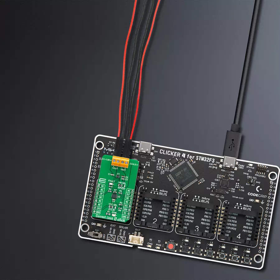
Current Limit 5 Click
Dev. board
CLICKER 4 for STM32F302VCT6
Compiler
NECTO Studio
MCU
STM32F302VC
Experience the future of confident current management with our solution, where precision ensures optimal performance and efficiency, while protecting your systems from potential overloads
A
A
Hardware Overview
How does it work?
Current Limit 5 Click is based on the MIC2099, a current-limiting device with an adjustable overcurrent protection feature from Microchip Technology. The MIC2099 offers flexible protection boundaries for systems against input voltage ranging from 2.5V to 5.5V and limits the output load current to a programmed level (up to 1.05A). Additional safety features include thermal shutdown protection to prevent overheating, under-voltage lock-out, a soft start that prevents large current inrush, and automatic-on output after a fault condition. The current-limit switch is virtually ubiquitous in system control and provides a safe means for regulating the current delivered to a load circuit. It increases the load current to a programmed limit but no higher. Typically, the current limit is a function of the voltage across an
external resistor, and this voltage serves as the reference for an internal current-limiting amplifier. Replacing the resistor with a digital potentiometer allows you to program the current limit as performed on this Click board™. For this purpose, the digital potentiometer MCP4561 from Microchip Technology, which communicates with the MCU via a 2-wire I2C serial interface, is used to set the resistance on the MIC2099 LIMIT pin, adjusting the current limit for the switch between 0.1A to 1.05A. Current Limit 5 Click can be turned on, or off through the EN pin routed to the CS pin of the mikroBUS™ socket, hence offering a switch operation to turn ON/OFF power delivery to the connected load. It also provides a fault status indication signal, labeled as FLT and routed to the INT pin of the mikroBUS™ socket, alongside its
LED indicator marked as FAULT to indicate different fault conditions such as current limit and thermal shutdown. This Click board™ can operate with both 3.3V and 5V logic voltage levels selected via the VCC SEL jumper. It allows both 3.3V and 5V capable MCUs to use the communication lines properly. Additionally, there is a possibility for the MIC2099 power supply selection via jumper labeled as VIN SEL to supply the MIC2099 from an external power supply VEXT terminal in the range from 2.5V to 5.5V or with VCC voltage levels from mikroBUS™ power rails. Also, this Click board™ comes equipped with a library containing easy-to-use functions and an example code that can be used as a reference for further development.

Features overview
Development board
Clicker 4 for STM32F3 is a compact development board designed as a complete solution, you can use it to quickly build your own gadgets with unique functionalities. Featuring a STM32F302VCT6, four mikroBUS™ sockets for Click boards™ connectivity, power managment, and more, it represents a perfect solution for the rapid development of many different types of applications. At its core, there is a STM32F302VCT6 MCU, a powerful microcontroller by STMicroelectronics, based on the high-
performance Arm® Cortex®-M4 32-bit processor core operating at up to 168 MHz frequency. It provides sufficient processing power for the most demanding tasks, allowing Clicker 4 to adapt to any specific application requirements. Besides two 1x20 pin headers, four improved mikroBUS™ sockets represent the most distinctive connectivity feature, allowing access to a huge base of Click boards™, growing on a daily basis. Each section of Clicker 4 is clearly marked, offering an intuitive and clean interface. This makes working with the development
board much simpler and thus, faster. The usability of Clicker 4 doesn’t end with its ability to accelerate the prototyping and application development stages: it is designed as a complete solution which can be implemented directly into any project, with no additional hardware modifications required. Four mounting holes [4.2mm/0.165”] at all four corners allow simple installation by using mounting screws. For most applications, a nice stylish casing is all that is needed to turn the Clicker 4 development board into a fully functional, custom design.

Microcontroller Overview
MCU Card / MCU

Architecture
ARM Cortex-M4
MCU Memory (KB)
256
Silicon Vendor
STMicroelectronics
Pin count
100
RAM (Bytes)
40960
Used MCU Pins
mikroBUS™ mapper
Take a closer look
Click board™ Schematic

Step by step
Project assembly

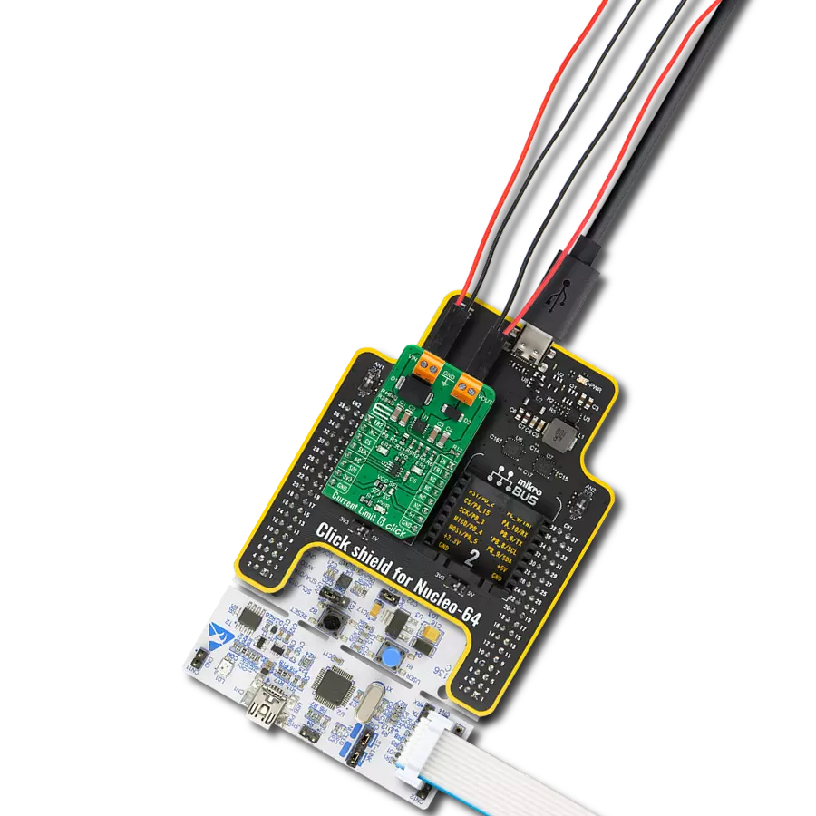
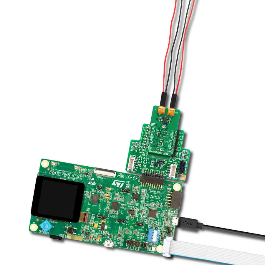
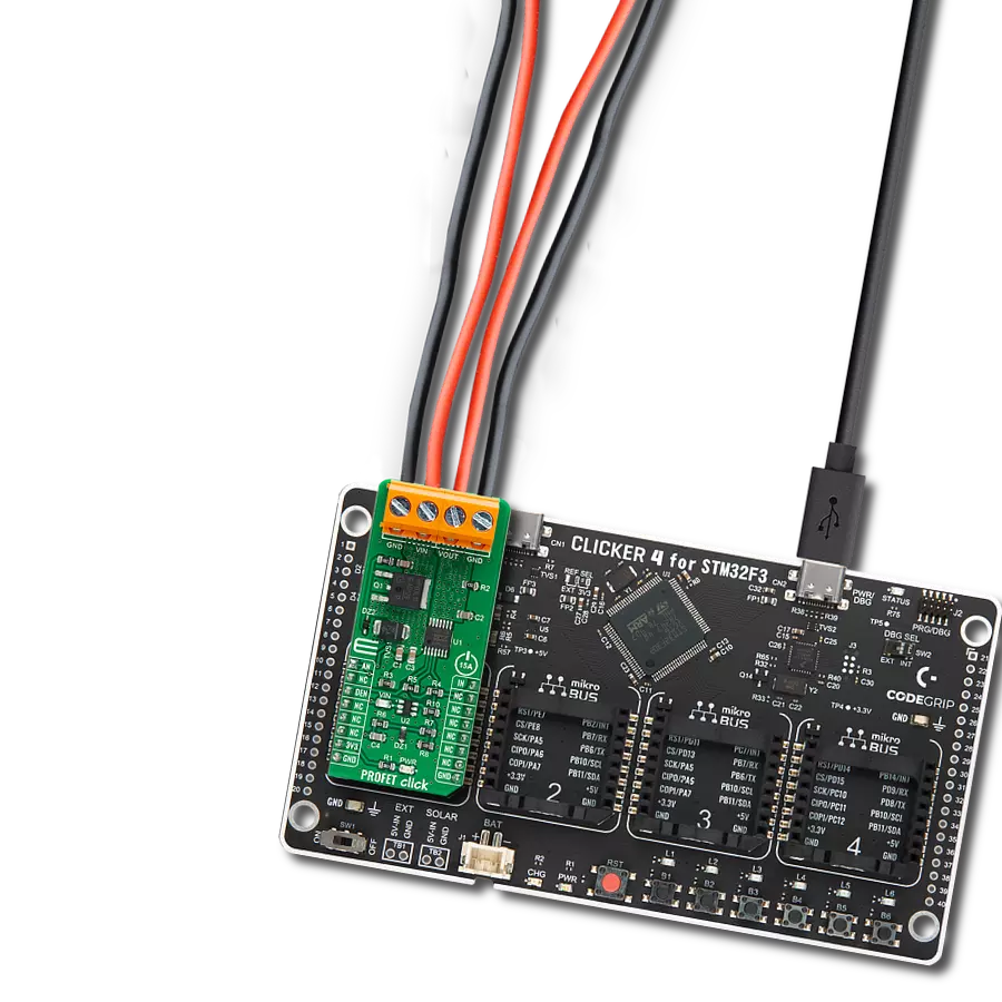
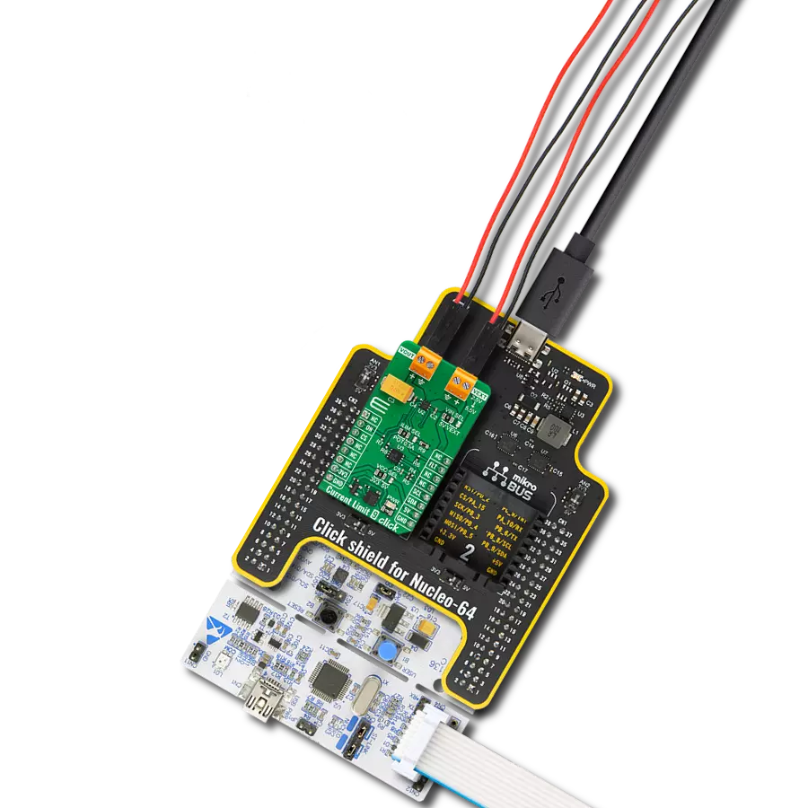
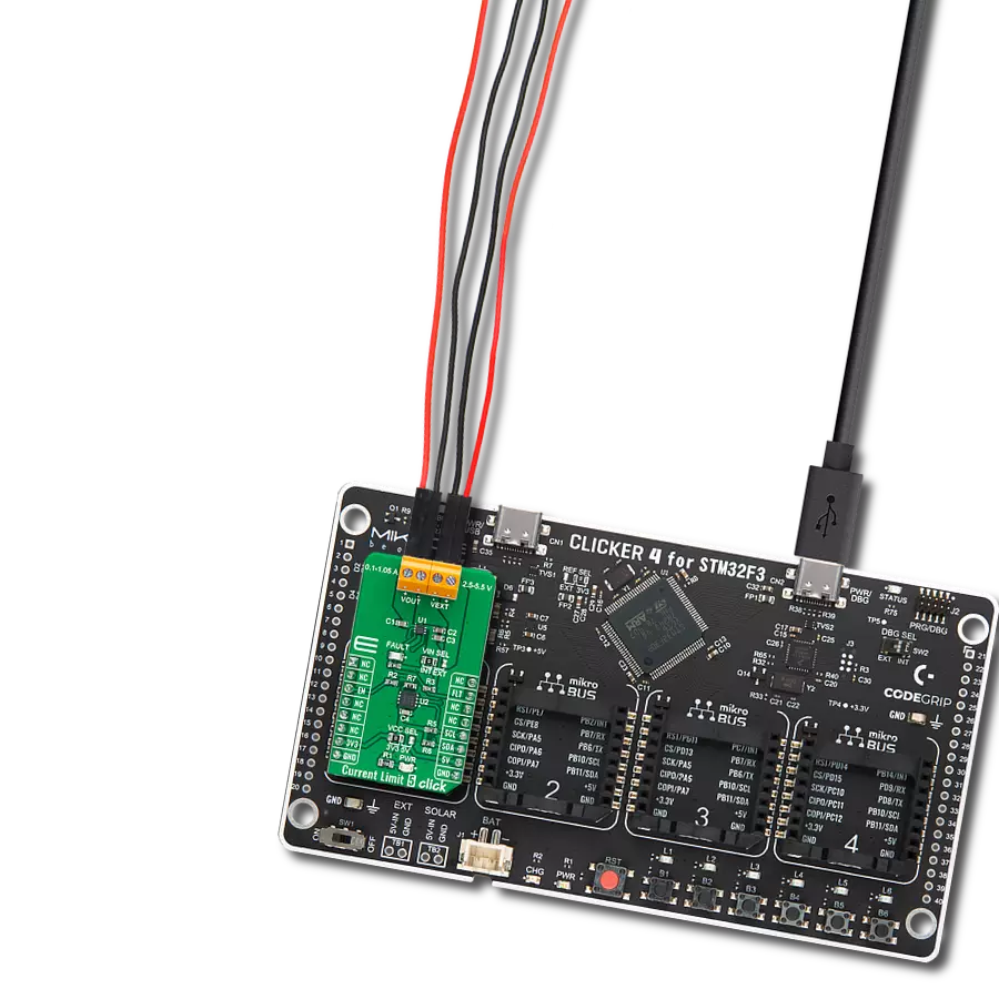
Start by selecting your development board and Click board™. Begin with the CLICKER 4 for STM32F302VCT6 as your development board.


Track your results in real time
Application Output
1. Application Output - In Debug mode, the 'Application Output' window enables real-time data monitoring, offering direct insight into execution results. Ensure proper data display by configuring the environment correctly using the provided tutorial.

2. UART Terminal - Use the UART Terminal to monitor data transmission via a USB to UART converter, allowing direct communication between the Click board™ and your development system. Configure the baud rate and other serial settings according to your project's requirements to ensure proper functionality. For step-by-step setup instructions, refer to the provided tutorial.

3. Plot Output - The Plot feature offers a powerful way to visualize real-time sensor data, enabling trend analysis, debugging, and comparison of multiple data points. To set it up correctly, follow the provided tutorial, which includes a step-by-step example of using the Plot feature to display Click board™ readings. To use the Plot feature in your code, use the function: plot(*insert_graph_name*, variable_name);. This is a general format, and it is up to the user to replace 'insert_graph_name' with the actual graph name and 'variable_name' with the parameter to be displayed.

Software Support
Library Description
This library contains API for Current Limit 5 Click driver.
Key functions:
currentlimit5_set_ilimit- This function sets the current limit value by configuring the onboard digital potentiometercurrentlimit5_get_fault_pin- This function returns the fault pin logic statecurrentlimit5_enable_limit- This function enables the current limiting switch
Open Source
Code example
The complete application code and a ready-to-use project are available through the NECTO Studio Package Manager for direct installation in the NECTO Studio. The application code can also be found on the MIKROE GitHub account.
/*!
* @file main.c
* @brief CurrentLimit5 Click example
*
* # Description
* This example demonstrates the use of Current Limit 5 Click board by limiting
* the current to a certain value and displaying an appropriate message when the current
* reaches the limit.
*
* The demo application is composed of two sections :
*
* ## Application Init
* Initializes the driver and performs the Click default configuration which sets
* the current limit to 200mA.
*
* ## Application Task
* Displays the fault indicator state on the USB UART.
*
* @author Stefan Filipovic
*
*/
#include "board.h"
#include "log.h"
#include "currentlimit5.h"
static currentlimit5_t currentlimit5;
static log_t logger;
void application_init ( void )
{
log_cfg_t log_cfg; /**< Logger config object. */
currentlimit5_cfg_t currentlimit5_cfg; /**< Click config object. */
/**
* Logger initialization.
* Default baud rate: 115200
* Default log level: LOG_LEVEL_DEBUG
* @note If USB_UART_RX and USB_UART_TX
* are defined as HAL_PIN_NC, you will
* need to define them manually for log to work.
* See @b LOG_MAP_USB_UART macro definition for detailed explanation.
*/
LOG_MAP_USB_UART( log_cfg );
log_init( &logger, &log_cfg );
log_info( &logger, " Application Init " );
// Click initialization.
currentlimit5_cfg_setup( ¤tlimit5_cfg );
CURRENTLIMIT5_MAP_MIKROBUS( currentlimit5_cfg, MIKROBUS_1 );
if ( I2C_MASTER_ERROR == currentlimit5_init( ¤tlimit5, ¤tlimit5_cfg ) )
{
log_error( &logger, " Communication init." );
for ( ; ; );
}
if ( CURRENTLIMIT5_ERROR == currentlimit5_default_cfg ( ¤tlimit5 ) )
{
log_error( &logger, " Default configuration." );
for ( ; ; );
}
log_info( &logger, " Application Task " );
}
void application_task ( void )
{
static uint8_t currentlimit_ind = 2;
if ( currentlimit5_get_fault_pin ( ¤tlimit5 ) )
{
if ( currentlimit_ind != 0 )
{
log_printf ( &logger, " The switch is in normal operation \r\n\n" );
currentlimit_ind = 0;
}
}
else
{
if ( currentlimit_ind != 1 )
{
log_printf ( &logger, " The switch is in the current limiting or thermal shutdown operation \r\n\n" );
currentlimit_ind = 1;
}
}
}
int main ( void )
{
/* Do not remove this line or clock might not be set correctly. */
#ifdef PREINIT_SUPPORTED
preinit();
#endif
application_init( );
for ( ; ; )
{
application_task( );
}
return 0;
}
// ------------------------------------------------------------------------ END
Additional Support
Resources
Category:Power Switch