Accurate alcohol detection based on the MiCS-5524 and STM32L152RE
Alcohol awareness simplified: Our detection, your safe passage

Published Aug 29, 2023
Click board™
Alcohol 3 Click
Dev. board
Fusion for ARM v8
Compiler
NECTO Studio
MCU
STM32L152RE
Develop top-of-the-line alcohol breath tester and early fire and gas leakage detection applications easily
A
A
Hardware Overview
How does it work?
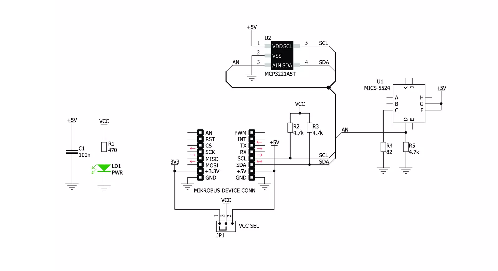
Alcohol 3 Click is based on the MiCS-5524 sensor, a compact MOS sensor from SGX Sensortech. This sensor comprises a micromachined metal oxide semiconductor diaphragm with an integrated heating resistor. The resistor produces heat, which catalyzes the reaction, affecting the electrical resistance of the oxide layer itself. The temperature of the heater is quite high: it ranges from 350 °C to 550 °C. After the initial preheating period, the sensor can detect gas changes in intervals below two seconds. The resistance of the MiCS-5524 sensor does not change linearly with the gas concentration, so a proper calibration must be performed before using it for absolute gas concentration measurement applications. The impedance changes the most when used with low gas concentrations. As the atmosphere gets saturated with gas, the impedance changes slowly. This should be considered, especially when
developing applications for estimating blood alcohol content (BAC) from a breath sample (also known as a breathalyzer). The MiCS-5524 sensor is a simple device: it has only four connections. Two pins are the connections of the internal heating element, while the other two are the MOS sensor connections. The application is reduced to calculating a proper resistor for the voltage divider. The datasheet of the MiCS-5524 sensor offers typical values for its resistance when used in clean air (artificial conditions). The sensitivity is then expressed as the ratio between the sensor's resistance in clean air and resistance at a concentration of 60 ppm CO. The middle tap between the sensor (as a resistor) and the fixed resistance provides an output voltage. It depends on the sensor's resistance, allowing it to be used as the input into the MCP3221, a low-power 12-bit A/D converter with an I2C interface, from Microchip.
This ADC allows the output voltage to be translated into digital information, accessed over the I2C pins on the mikroBUS™ socket. By using the power supply voltage as the voltage reference for the conversion, this ADC further reduces the complexity of the design, still offering a good conversion quality, thanks to its low noise input. Due to the sensor's inert nature, this ADC is more than fast enough, although it can provide up to 22.3ksps when operated in the I2C Fast mode. This Click board™ can operate with either 3.3V or 5V logic voltage levels selected via the VCC SEL jumper. This way, both 3.3V and 5V capable MCUs can use the communication lines properly. Also, this Click board™ comes equipped with a library containing easy-to-use functions and an example code that can be used as a reference for further development.


Features overview
Development board
Fusion for ARM v8 is a development board specially designed for the needs of rapid development of embedded applications. It supports a wide range of microcontrollers, such as different ARM® Cortex®-M based MCUs regardless of their number of pins, and a broad set of unique functions, such as the first-ever embedded debugger/programmer over WiFi. The development board is well organized and designed so that the end-user has all the necessary elements, such as switches, buttons, indicators, connectors, and others, in one place. Thanks to innovative manufacturing technology, Fusion for ARM v8 provides a fluid and immersive working experience, allowing access anywhere and under any
circumstances at any time. Each part of the Fusion for ARM v8 development board contains the components necessary for the most efficient operation of the same board. An advanced integrated CODEGRIP programmer/debugger module offers many valuable programming/debugging options, including support for JTAG, SWD, and SWO Trace (Single Wire Output)), and seamless integration with the Mikroe software environment. Besides, it also includes a clean and regulated power supply module for the development board. It can use a wide range of external power sources, including a battery, an external 12V power supply, and a power source via the USB Type-C (USB-C) connector.
Communication options such as USB-UART, USB HOST/DEVICE, CAN (on the MCU card, if supported), and Ethernet is also included. In addition, it also has the well-established mikroBUS™ standard, a standardized socket for the MCU card (SiBRAIN standard), and two display options for the TFT board line of products and character-based LCD. Fusion for ARM v8 is an integral part of the Mikroe ecosystem for rapid development. Natively supported by Mikroe software tools, it covers many aspects of prototyping and development thanks to a considerable number of different Click boards™ (over a thousand boards), the number of which is growing every day.

Microcontroller Overview
MCU Card / MCU
Type
8th Generation
Architecture
ARM Cortex-M3
MCU Memory (KB)
512
Silicon Vendor
STMicroelectronics
Pin count
64
RAM (Bytes)
81920
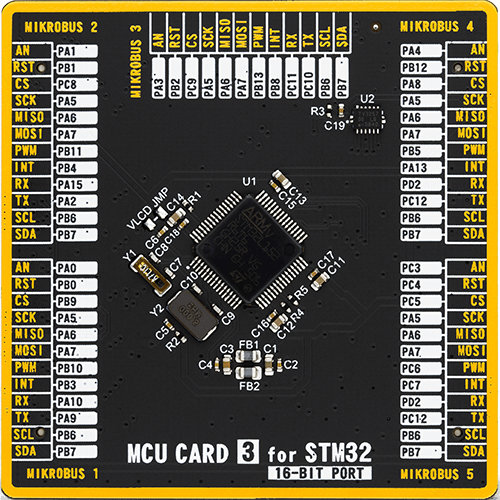
Used MCU Pins
mikroBUS™ mapper
Take a closer look
Click board™ Schematic
Step by step
Project assembly

Start by selecting your development board and Click board™. Begin with the Fusion for ARM v8 as your development board.


Software Support
Library Description
This library contains API for Alcohol 3 Click driver.
Key functions:
alcohol3_get_co_in_ppm- This function reads CO (Carbon monoxide) data in ppm (1 ppm - 1000 ppm)alcohol3_get_percentage_bac- This function reads percentage of alcohol in the blood (BAC)alcohol3_get_adc_data- This function reads 12bit ADC value.
Open Source
Code example
The complete application code and a ready-to-use project are available through the NECTO Studio Package Manager for direct installation in the NECTO Studio. The application code can also be found on the MIKROE GitHub account.
/*!
 * \file
 * \brief Alcohol3 Click example
 *
 * # Description
 * Code of this sensor reacts to the presence of deoxidizing and reducing gases,
 * such as ethanol (also known as alcohol).
 *
 * The demo application is composed of two sections :
 *
 * ## Application Init
 * Application Init performs Logger and Click initialization.
 *
 * ## Application Task
 * Reads percentage of alcohol in the blood (BAC)
 * and this data logs to USBUART every 1 sec.
 *
 * \author MikroE Team
 *
 */
// ------------------------------------------------------------------- INCLUDES

#include "board.h"
#include "log.h"
#include "alcohol3.h"

// ------------------------------------------------------------------ VARIABLES

static alcohol3_t alcohol3;
static log_t logger;

// ------------------------------------------------------ APPLICATION FUNCTIONS

void application_init ( void )
{
    log_cfg_t log_cfg;
    alcohol3_cfg_t cfg;

    /**
     * Logger initialization.
     * Default baud rate: 115200
     * Default log level: LOG_LEVEL_DEBUG
     * @note If USB_UART_RX and USB_UART_TX
     * are defined as HAL_PIN_NC, you will
     * need to define them manually for log to work.
     * See @b LOG_MAP_USB_UART macro definition for detailed explanation.
     */
    LOG_MAP_USB_UART( log_cfg );
    log_init( &logger, &log_cfg );
    log_info( &logger, "---- Application Init ----" );
    Delay_ms ( 100 );

    //  Click initialization.

    alcohol3_cfg_setup( &cfg );
    ALCOHOL3_MAP_MIKROBUS( cfg, MIKROBUS_1 );
    alcohol3_init( &alcohol3, &cfg );

    log_printf( &logger, "--------------------------\r\n\n" );
    log_printf( &logger, " ---- Alcohol 3 Click ----\r\n" );
    log_printf( &logger, "--------------------------\r\n\n" );
    Delay_ms ( 1000 );

    log_printf( &logger, " ---- Initialization ---\r\n" );
    log_printf( &logger, "--------------------------\r\n\n" );
    Delay_ms ( 1000 );
}

void application_task ( void )
{
    uint16_t co_ppm;
    uint16_t p_bac;
    float temp_bac;

    //  Task implementation.

    log_printf( &logger, " --- Alcohol diagnostics ---- \r\n" );

    co_ppm = alcohol3_get_co_in_ppm ( &alcohol3 );
    log_printf( &logger, " co in ppm  %d    | \r\n", co_ppm );

    temp_bac = alcohol3_get_percentage_bac( &alcohol3 );
    p_bac = ( uint16_t )( temp_bac * 1000 );

    if ( 10 > p_bac && p_bac < 100 )
    {
        log_printf( &logger, " BAC      | 0.00%d\r\n", p_bac );
    }
    else if ( 100 <= p_bac && 1000 > p_bac )
    {
        log_printf( &logger, " BAC      | 0.0%d\r\n", p_bac );
    }
    else if ( p_bac >= 1000 )
    {
        log_printf( &logger, " BAC      | 0.%d\r\n", p_bac );
    }
    else
    {
        log_printf( &logger, " BAC  | 0.0000\r\n" );
    }
    log_printf( &logger, " ---------------------------- \r\n" );

    Delay_ms ( 1000 );
}

int main ( void )
{
    /* Do not remove this line or clock might not be set correctly. */
    #ifdef PREINIT_SUPPORTED
    preinit();
    #endif

    application_init( );

    for ( ; ; )
    {
        application_task( );
    }

    return 0;
}


// ------------------------------------------------------------------------ END
Additional Support
Resources
Category:Gas


