Breathe easier with ATmega324P
Say goodbye to air pollution

Published Aug 29, 2023
Click board™
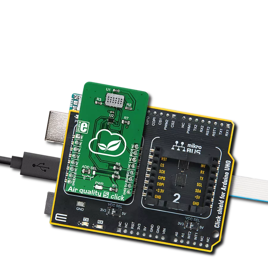
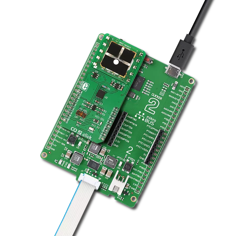
Air quality 3 Click
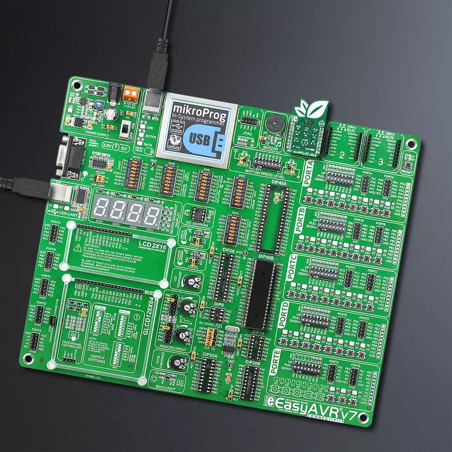
Dev. board
EasyAVR v7
Compiler
NECTO Studio
MCU
ATmega324P
Our cutting-edge air quality monitor is vital in urban planning, equipping city officials with essential data to shape policies that prioritize citizen well-being
A
A
Hardware Overview
How does it work?
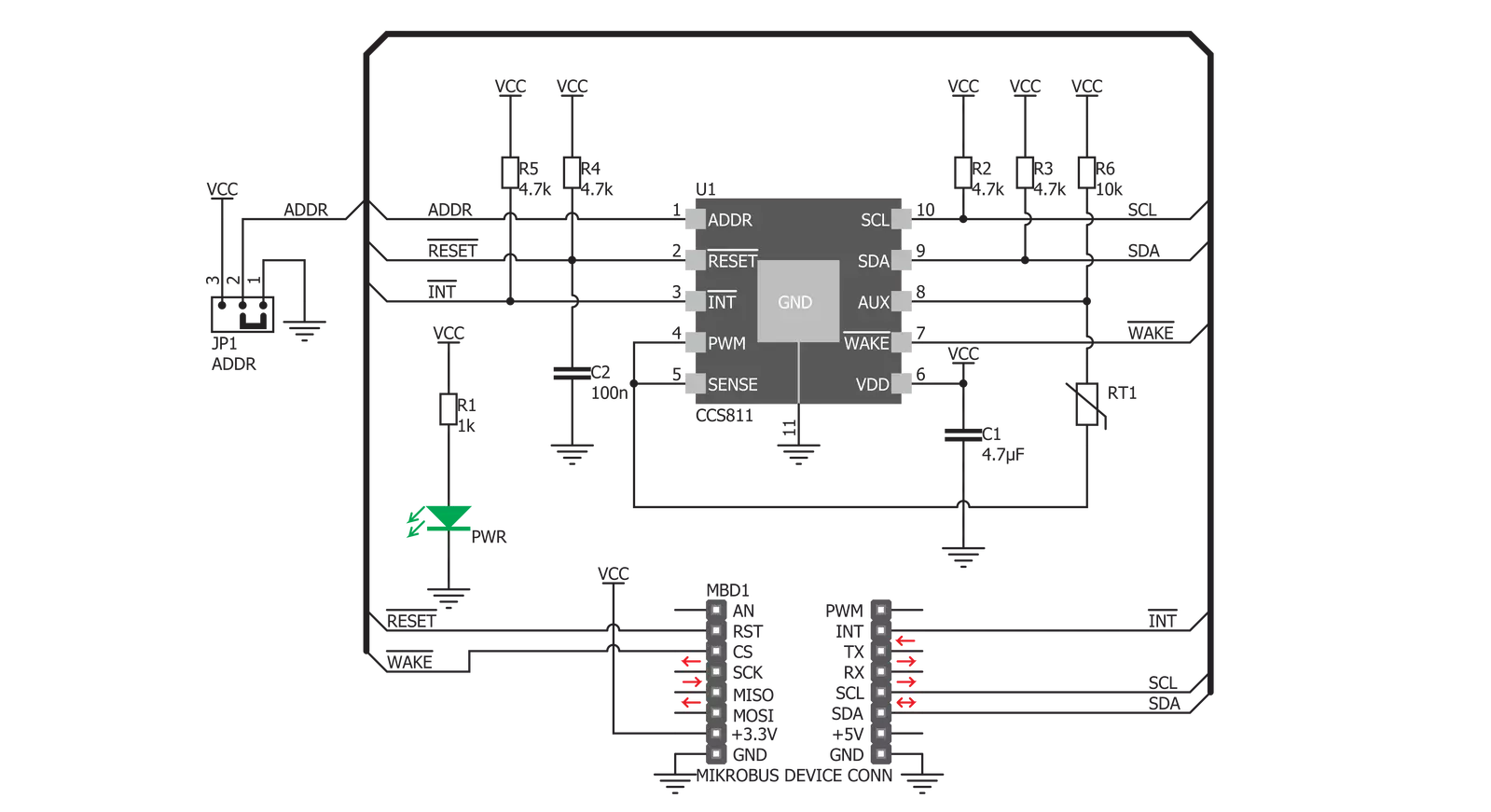
Air Quality 3 Click is based on the CCS811, an advanced ultra-low power digital gas sensor for monitoring indoor air quality (IAQ) from ScioSense. This IC consists of an analog section consisting of a MOX gas sensor based on ScioSense unique micro-hotplate technology, which allows high reliability, fast cycle times, and low power consumption, and the digital section, which consists of an embedded microcontroller (MCU) and an analog to digital converter (ADC). The CCS811 sensor IC employs advanced algorithms to calculate the raw sensor data and output the equivalent CO2 and TVOC values. It utilizes the internal MCU for this purpose, reducing the payload on the host MCU. Because of the nature of the MOX sensors, the CCS811 sensitivity will change over time, especially in early-life use. The internal sensor resistance will change the most for the first 48 hours of operation. So, to achieve proper operation of this sensor, it has to be calibrated during several different phases of its lifecycle. Since this step is important for achieving accurate IAQ results, it is strongly advised to be
carefully studied from the CCS811 datasheet. The Click board™ communicates with the host MCU via the I2C bus. SCL and SDA pins of the CCS811 IC are routed to the corresponding mikroBUS™ pins, allowing an easy and secure connection with the development system. Yet another pin is used with the I2C communication that is not part of the standard I2C bus: the #WAKE pin has to be set to a LOW logic level before the communication is attempted. This pin is routed to the CS pin of the mikroBUS™. The I2C bus lines are equipped with pull-up resistors, so communication can be established as soon as the click board is installed on the mikroBUS™. The least significant bit of the I2C address is routed to the external pin of the CCS811 IC, and it can be set to either a HIGH or a LOW logic level. This can be done by an onboard SMD jumper labeled as ADDR. It is useful when multiple devices are used on the same I2C bus. The #RESET pin is used to reset the device and must be pulled to a LOW logic level for at least 20μs. It is pulled to a HIGH logic level by the onboard resistor and filtered by a capacitor
to prevent random reset of the device. The #RESET of the CCS811 sensor IC is routed to the mikroBUS RST pin. The #INT pin allows another powerful Air Quality 3 Click feature to be used - a programmable interrupt request. This pin can be driven to a LOW state when data is ready to be read via the I2C. It can also be programmed to be driven when the eCO2 measurement data exceeds the programmed threshold by the hysteresis value. This can be extremely useful for making an early CO2 warning system. Interrupts, in general, are useful to avoid constant polling by the MCU, saving resources and energy that way. The #INT of the CCS811 sensor IC is routed to the mikroBUS INT pin. This Click board™ can be operated only with a 3.3V logic voltage level. The board must perform appropriate logic voltage level conversion before using MCUs with different logic levels. Also, it comes equipped with a library containing functions and an example code that can be used as a reference for further development.


Features overview
Development board
EasyAVR v7 is the seventh generation of AVR development boards specially designed for the needs of rapid development of embedded applications. It supports a wide range of 16-bit AVR microcontrollers from Microchip and has a broad set of unique functions, such as a powerful onboard mikroProg programmer and In-Circuit debugger over USB. The development board is well organized and designed so that the end-user has all the necessary elements in one place, such as switches, buttons, indicators, connectors, and others. With four different connectors for each port, EasyAVR v7 allows you to connect accessory boards, sensors, and custom electronics more
efficiently than ever. Each part of the EasyAVR v7 development board contains the components necessary for the most efficient operation of the same board. An integrated mikroProg, a fast USB 2.0 programmer with mikroICD hardware In-Circuit Debugger, offers many valuable programming/debugging options and seamless integration with the Mikroe software environment. Besides it also includes a clean and regulated power supply block for the development board. It can use a wide range of external power sources, including an external 12V power supply, 7-12V AC or 9-15V DC via DC connector/screw terminals, and a power source via the USB Type-B (USB-B)
connector. Communication options such as USB-UART and RS-232 are also included, alongside the well-established mikroBUS™ standard, three display options (7-segment, graphical, and character-based LCD), and several different DIP sockets which cover a wide range of 16-bit AVR MCUs. EasyAVR v7 is an integral part of the Mikroe ecosystem for rapid development. Natively supported by Mikroe software tools, it covers many aspects of prototyping and development thanks to a considerable number of different Click boards™ (over a thousand boards), the number of which is growing every day.

Microcontroller Overview
MCU Card / MCU

Architecture
AVR
MCU Memory (KB)
32
Silicon Vendor
Microchip
Pin count
40
RAM (Bytes)
2048
Used MCU Pins
mikroBUS™ mapper
Take a closer look
Click board™ Schematic
Step by step
Project assembly

Start by selecting your development board and Click board™. Begin with the EasyAVR v7 as your development board.


Track your results in real time
Application Output
1. Application Output - In Debug mode, the 'Application Output' window enables real-time data monitoring, offering direct insight into execution results. Ensure proper data display by configuring the environment correctly using the provided tutorial.

2. UART Terminal - Use the UART Terminal to monitor data transmission via a USB to UART converter, allowing direct communication between the Click board™ and your development system. Configure the baud rate and other serial settings according to your project's requirements to ensure proper functionality. For step-by-step setup instructions, refer to the provided tutorial.

3. Plot Output - The Plot feature offers a powerful way to visualize real-time sensor data, enabling trend analysis, debugging, and comparison of multiple data points. To set it up correctly, follow the provided tutorial, which includes a step-by-step example of using the Plot feature to display Click board™ readings. To use the Plot feature in your code, use the function: plot(*insert_graph_name*, variable_name);. This is a general format, and it is up to the user to replace 'insert_graph_name' with the actual graph name and 'variable_name' with the parameter to be displayed.

Software Support
Library Description
This library contains API for Air Quality 3 Click driver.
Key functions:
airquality3_get_co2_and_tvoc- Get CO2 and TVOC dataairquality3_set_environment_data- Temperature and humidity data settingsairquality3_set_measurement_mode- Function for settings sensor drive mode and interrupts.
Open Source
Code example
The complete application code and a ready-to-use project are available through the NECTO Studio Package Manager for direct installation in the NECTO Studio. The application code can also be found on the MIKROE GitHub account.
/*!
 * \file
 * \brief AirQuality3 Click example
 *
 * # Description
 * The demo application shows air quality measurement.
 *
 * The demo application is composed of two sections :
 *
 * ## Application Init
 * Configuring Clicks and log objects.
 * Settings the Click in the default configuration.
 * Call the procedure the wakeup function of the chip.
 *
 * ## Application Task
 * Reads CO2 and TVOC value in the air and logs this data on the USBUART.
 *
 * \author Katarina Perendic
 *
 */
// ------------------------------------------------------------------- INCLUDES

#include "board.h"
#include "log.h"
#include "airquality3.h"

// ------------------------------------------------------------------ VARIABLES

static airquality3_t airquality3;
static log_t logger;

// ------------------------------------------------------ APPLICATION FUNCTIONS

void application_init ( void )
{
    log_cfg_t log_cfg;
    airquality3_cfg_t cfg;

    /**
     * Logger initialization.
     * Default baud rate: 115200
     * Default log level: LOG_LEVEL_DEBUG
     * @note If USB_UART_RX and USB_UART_TX
     * are defined as HAL_PIN_NC, you will
     * need to define them manually for log to work.
     * See @b LOG_MAP_USB_UART macro definition for detailed explanation.
     */
    LOG_MAP_USB_UART( log_cfg );
    log_init( &logger, &log_cfg );
    log_info( &logger, "---- Application Init ----" );

    //  Click initialization.

    airquality3_cfg_setup( &cfg );
    AIRQUALITY3_MAP_MIKROBUS( cfg, MIKROBUS_1 );
    airquality3_init( &airquality3, &cfg );

    // Wake-up Click procedure

    airquality3_set_power( &airquality3, AIRQUALITY3_POWER_STATE_ON );
    airquality3_hardware_reset( &airquality3 );
    airquality3_app_function( &airquality3, AIRQUALITY3_APP_START );

    airquality3_default_cfg( &airquality3 );

    Delay_ms ( 500 );
    log_info( &logger, "---- Start measurement ----" );
}

void application_task ( void )
{
    airquality3_air_data_t air_data;

    //  Task implementation.

    airquality3_get_co2_and_tvoc ( &airquality3, &air_data );
    log_printf( &logger, "\r\n---- AirQuality data ----\r\n" );
    log_printf( &logger, ">> CO2 data is %d ppm.\r\n", air_data.co2 );
    log_printf( &logger, ">> TVOC data is %d ppb.\r\n", air_data.tvoc );

    Delay_1sec( );
}

int main ( void )
{
    /* Do not remove this line or clock might not be set correctly. */
    #ifdef PREINIT_SUPPORTED
    preinit();
    #endif

    application_init( );

    for ( ; ; )
    {
        application_task( );
    }

    return 0;
}


// ------------------------------------------------------------------------ END