Achieve real-time monitoring of ozone levels with MQ131 and STM32F031K6 and ensure a safer environment for all
Ozone watch: Your guardian for air purity!

Published Oct 01, 2024
Click board™
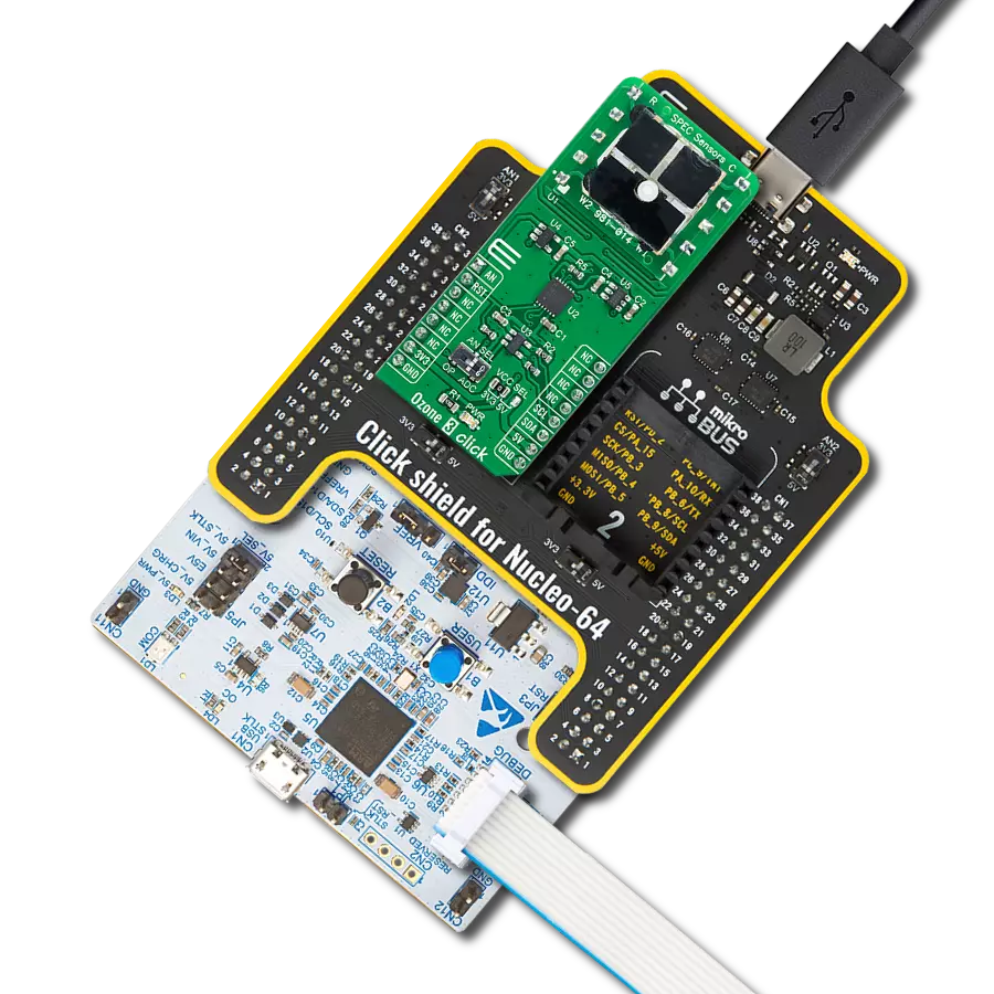
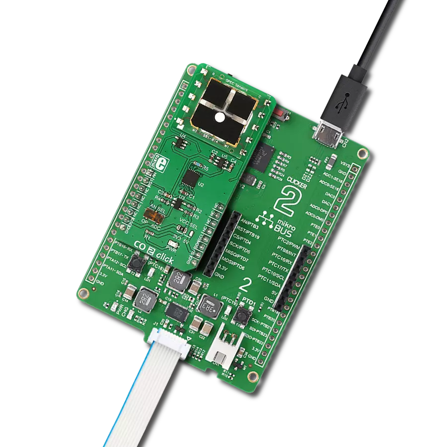
Ozone 2 Click
Dev. board
Nucleo 32 with STM32F031K6 MCU
Compiler
NECTO Studio
MCU
STM32F031K6
Designed for both indoor and outdoor use, our ozone-sensing solution plays a pivotal role in maintaining healthy air quality standards for homes, offices, and public spaces
A
A
Hardware Overview
How does it work?
Ozone 2 Click is based on the MQ131, an ozone (O3) gas sensor from Winsen, which uses the SnO2 (tin-oxide) alloy, which decreases its resistance while exposed to the O3 gas. The greater the O3 concentration is, the more conductive this material becomes. This can be utilized to obtain the O3 concentration readings. The sensor contains a small heating element connected to a 5V power supply. It must be preheated for 48 hours before performing as specified. The sensor's sensitivity is given as the ratio between the air resistance and the O3 gas concentration of 50ppm, which is ≥ 3 (RO/RS ≥ 3). A stainless mesh protects The sensor against particles and mechanical damage; however, exposure to excessive moisture and corrosive gases can damage the inner structure. The measuring circuit consists of the MQ131 sensor, a power source, and a
load resistor (RL) between the output pin and GND. With its internal resistance, the sensor forms a voltage divider with the load resistor. The RL is designed as a variable resistor, allowing the output voltage to be trimmed to the desired value. The calibration should be performed in controlled conditions, as the ambient temperature and humidity affect the sensor's resistance. The sensor can measure relative O3 concentration change without accurate calibration, which is useful for building applications that can be used as warning systems. The middle tap of the sensor-RL voltage divider is routed to an SMD jumper labeled ADC SEL. This jumper can redirect the measuring voltage to the ADC for sampling or the AN pin so that it can be used in an external circuitry (external ADC or some other form of measurement signal conditioning). The MCP3551, a 22-bit sigma-delta
ADC from Microchip, is used to sample the sensor output when selected by the ADC SEL jumper. This ADC converts the input voltage, with a very high resolution of 22 bits and low noise, to digital data, which can be obtained via the SPI interface of the Click board™. This ADC uses the reference voltage, which is the same as the power supply voltage, and in this case, it is powered by 5V from the mikroBUS™ power rail. As already mentioned, the ADC uses a 5V power supply. Therefore, this board needs a level conversion circuitry interfacing with 3.3V MCUs. This Click board™ uses the TXB0106 IC, a 6-bit bidirectional level shifting IC from Texas Instruments, which is used to shift communication logic voltage levels from 5V to 3.3V. The voltage shift depends on the reference voltage on the VCCA pin, which can be selected with the SMD jumper labeled as the VCCIO SEL.


Features overview
Development board
Nucleo 32 with STM32F031K6 MCU board provides an affordable and flexible platform for experimenting with STM32 microcontrollers in 32-pin packages. Featuring Arduino™ Nano connectivity, it allows easy expansion with specialized shields, while being mbed-enabled for seamless integration with online resources. The
board includes an on-board ST-LINK/V2-1 debugger/programmer, supporting USB reenumeration with three interfaces: Virtual Com port, mass storage, and debug port. It offers a flexible power supply through either USB VBUS or an external source. Additionally, it includes three LEDs (LD1 for USB communication, LD2 for power,
and LD3 as a user LED) and a reset push button. The STM32 Nucleo-32 board is supported by various Integrated Development Environments (IDEs) such as IAR™, Keil®, and GCC-based IDEs like AC6 SW4STM32, making it a versatile tool for developers.

Microcontroller Overview
MCU Card / MCU

Architecture
ARM Cortex-M0
MCU Memory (KB)
32
Silicon Vendor
STMicroelectronics
Pin count
32
RAM (Bytes)
4096
You complete me!
Accessories
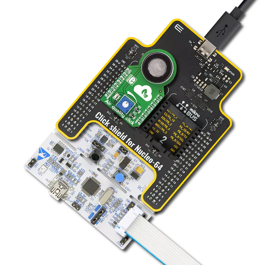
Click Shield for Nucleo-32 is the perfect way to expand your development board's functionalities with STM32 Nucleo-32 pinout. The Click Shield for Nucleo-32 provides two mikroBUS™ sockets to add any functionality from our ever-growing range of Click boards™. We are fully stocked with everything, from sensors and WiFi transceivers to motor control and audio amplifiers. The Click Shield for Nucleo-32 is compatible with the STM32 Nucleo-32 board, providing an affordable and flexible way for users to try out new ideas and quickly create prototypes with any STM32 microcontrollers, choosing from the various combinations of performance, power consumption, and features. The STM32 Nucleo-32 boards do not require any separate probe as they integrate the ST-LINK/V2-1 debugger/programmer and come with the STM32 comprehensive software HAL library and various packaged software examples. This development platform provides users with an effortless and common way to combine the STM32 Nucleo-32 footprint compatible board with their favorite Click boards™ in their upcoming projects.

Used MCU Pins
mikroBUS™ mapper
Take a closer look
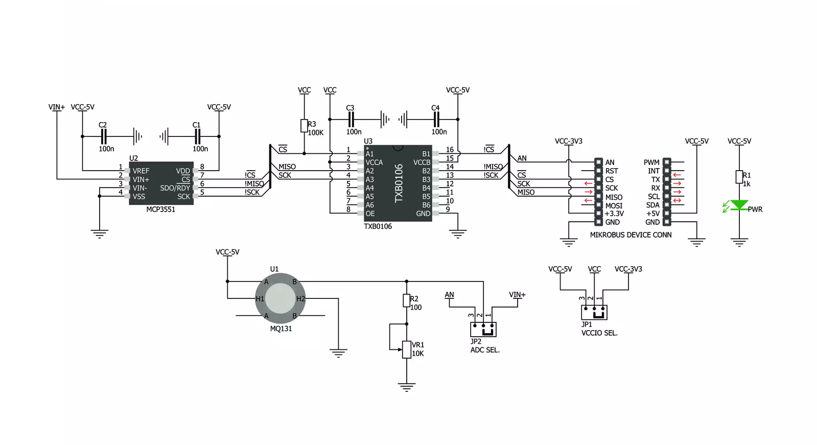
Click board™ Schematic
Step by step
Project assembly

Start by selecting your development board and Click board™. Begin with the Nucleo 32 with STM32F031K6 MCU as your development board.


Track your results in real time
Application Output
1. Application Output - In Debug mode, the 'Application Output' window enables real-time data monitoring, offering direct insight into execution results. Ensure proper data display by configuring the environment correctly using the provided tutorial.

2. UART Terminal - Use the UART Terminal to monitor data transmission via a USB to UART converter, allowing direct communication between the Click board™ and your development system. Configure the baud rate and other serial settings according to your project's requirements to ensure proper functionality. For step-by-step setup instructions, refer to the provided tutorial.

3. Plot Output - The Plot feature offers a powerful way to visualize real-time sensor data, enabling trend analysis, debugging, and comparison of multiple data points. To set it up correctly, follow the provided tutorial, which includes a step-by-step example of using the Plot feature to display Click board™ readings. To use the Plot feature in your code, use the function: plot(*insert_graph_name*, variable_name);. This is a general format, and it is up to the user to replace 'insert_graph_name' with the actual graph name and 'variable_name' with the parameter to be displayed.

Software Support
Library Description
This library contains API for Ozone 2 Click driver.
Key functions:
ozone2_read- This function reads from MCP 3351 ADC and returns 32 bit read value
Open Source
Code example
The complete application code and a ready-to-use project are available through the NECTO Studio Package Manager for direct installation in the NECTO Studio. The application code can also be found on the MIKROE GitHub account.
/*!
 * \file
 * \brief Ozone2 Click example
 *
 * # Description
 * This example shows the value of ozone measurement aquired from Ozone2 Click board.
 *
 * The demo application is composed of two sections :
 *
 * ## Application Init
 * Calls functions for driver initializaton used for data conversion and results reading.
 *
 * ## Application Task
 * Reads the level of ozone in the air every with repetition of 1 second.
 * This driver is able to get the level of ozone gas in the range from 10 to 1000 ppm.
 * #note#
 * Be sure that you correctly set the AD convertor which you want to use.
 *
 * \author Nemanja Medakovic
 *
 */
// ------------------------------------------------------------------- INCLUDES

#include "board.h"
#include "log.h"
#include "ozone2.h"

// ------------------------------------------------------------------ VARIABLES

static ozone2_t ozone2;
static log_t logger;

// ------------------------------------------------------ APPLICATION FUNCTIONS

void application_init ( void )
{
    log_cfg_t log_cfg;

    /**
     * Logger initialization.
     * Default baud rate: 115200
     * Default log level: LOG_LEVEL_DEBUG
     * @note If USB_UART_RX and USB_UART_TX
     * are defined as HAL_PIN_NC, you will
     * need to define them manually for log to work.
     * See @b LOG_MAP_USB_UART macro definition for detailed explanation.
     */
    LOG_MAP_USB_UART( log_cfg );
    log_init( &logger, &log_cfg );
    log_info( &logger, "---- Application Init... ----" );

    ozone2_cfg_t ozone2_cfg;

    //  Click initialization.

    ozone2_cfg_setup( &ozone2_cfg );
    OZONE2_MAP_MIKROBUS( ozone2_cfg, MIKROBUS_1 );

    if ( ozone2_init( &ozone2, &ozone2_cfg ) == OZONE2_INIT_ERROR )
    {
        log_info( &logger, "---- Application Init Error. ----" );
        log_info( &logger, "---- Please, run program again... ----" );

        for ( ; ; );
    }

    log_info( &logger, "---- Application Init Done. ----\n" );
}

void application_task ( void )
{
    uint16_t o3_ppm;

    if ( ozone2_read_measurement( &ozone2, &o3_ppm ) == OZONE2_OK )
    {
        log_printf( &logger, "  O3 [ppm] : %u\r\n", o3_ppm );
        Delay_ms ( 1000 );
    }
}

int main ( void )
{
    /* Do not remove this line or clock might not be set correctly. */
    #ifdef PREINIT_SUPPORTED
    preinit();
    #endif

    application_init( );

    for ( ; ; )
    {
        application_task( );
    }

    return 0;
}

// ------------------------------------------------------------------------ END