Gain valuable thermal insights with MLX90614 and STM32L496AG
Stay chilled and safeguarded - Zero contact needed!
Published Jul 22, 2025
Click board™
IrThermo Click
Dev. board
Discovery kit with STM32L496AG MCU
Compiler
NECTO Studio
MCU
STM32L496AG
Experience a secure temperature monitoring solution that keeps you cool and safe, eliminating the necessity for physical contact
A
A
Hardware Overview
How does it work?
IrThermo Click is based on the MLX90614, a single and dual-zone infrared thermometer from Melexis. This sensor is an IR sensor of a thermopile character. A thermopile sensor is a serially connected thermocouple array with hot junctions on the heat-absorbing membrane. The cold junctions are located on a cold base, providing the reference point for generating the voltage. Due to the low-temperature capacity of the membrane, it will react to the heat radiation, generating voltage via the thermoelectric effect. The ASSP circuitry of the MLX90614 sensor processes the voltage, allowing an accuracy of ±0.5˚C. The MLX90614 sensor is
factory calibrated in a wide temperature range: -40°C to 125°C for sensor temperature and -70°C to 380°C for object temperature. The ASSP circuitry also provides advanced interfacing options for the MCU, with the CRC error checking. The MLX90614 is equipped with a portion of EEPROM, which stores various config parameters, calibration data, and the chip ID address. Changing the values in the EEPROM will only take effect once the device is restarted. IrThermo Click 5V can use the SMBus to communicate with the host MCU using I2C lines of the mikroBUS™ socket. In addition, you can use the 10-bit PWM for data output to the host MCU.
The selection can be made over the SELECT MODE jumper, where the I2C is selected by default. For this Click board™ to work properly, both jumpers should be set to appropriate positions. This Click board™ can be operated only with a 5V logic voltage level. The board must perform appropriate logic voltage level conversion before using MCUs with different logic levels. Also, it comes equipped with a library containing functions and an example code that can be used as a reference for further development.

Features overview
Development board
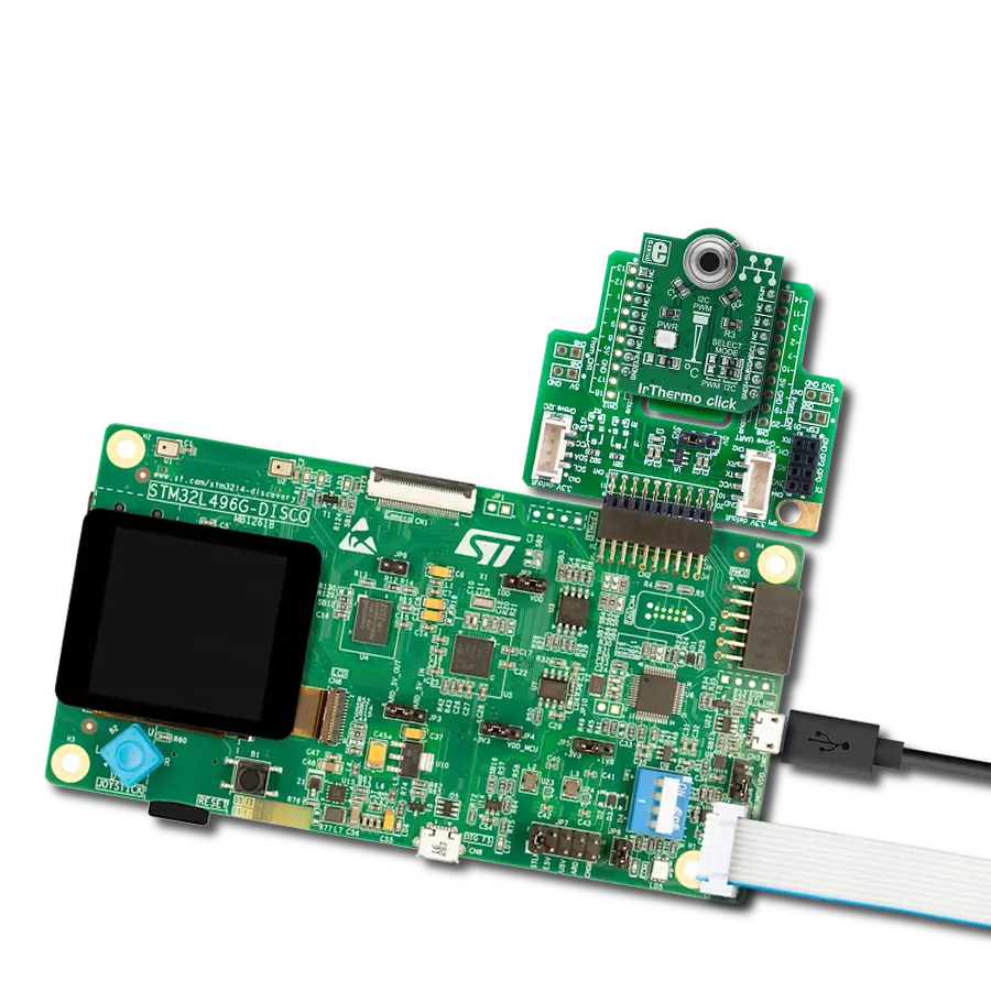
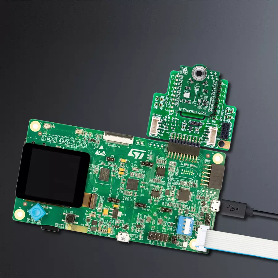
The 32L496GDISCOVERY Discovery kit serves as a comprehensive demonstration and development platform for the STM32L496AG microcontroller, featuring an Arm® Cortex®-M4 core. Designed for applications that demand a balance of high performance, advanced graphics, and ultra-low power consumption, this kit enables seamless prototyping for a wide range of embedded solutions. With its innovative energy-efficient
architecture, the STM32L496AG integrates extended RAM and the Chrom-ART Accelerator, enhancing graphics performance while maintaining low power consumption. This makes the kit particularly well-suited for applications involving audio processing, graphical user interfaces, and real-time data acquisition, where energy efficiency is a key requirement. For ease of development, the board includes an onboard ST-LINK/V2-1
debugger/programmer, providing a seamless out-of-the-box experience for loading, debugging, and testing applications without requiring additional hardware. The combination of low power features, enhanced memory capabilities, and built-in debugging tools makes the 32L496GDISCOVERY kit an ideal choice for prototyping advanced embedded systems with state-of-the-art energy efficiency.

Microcontroller Overview
MCU Card / MCU

Architecture
ARM Cortex-M4
MCU Memory (KB)
1024
Silicon Vendor
STMicroelectronics
Pin count
169
RAM (Bytes)
327680
Used MCU Pins
mikroBUS™ mapper
Take a closer look
Click board™ Schematic

Step by step
Project assembly

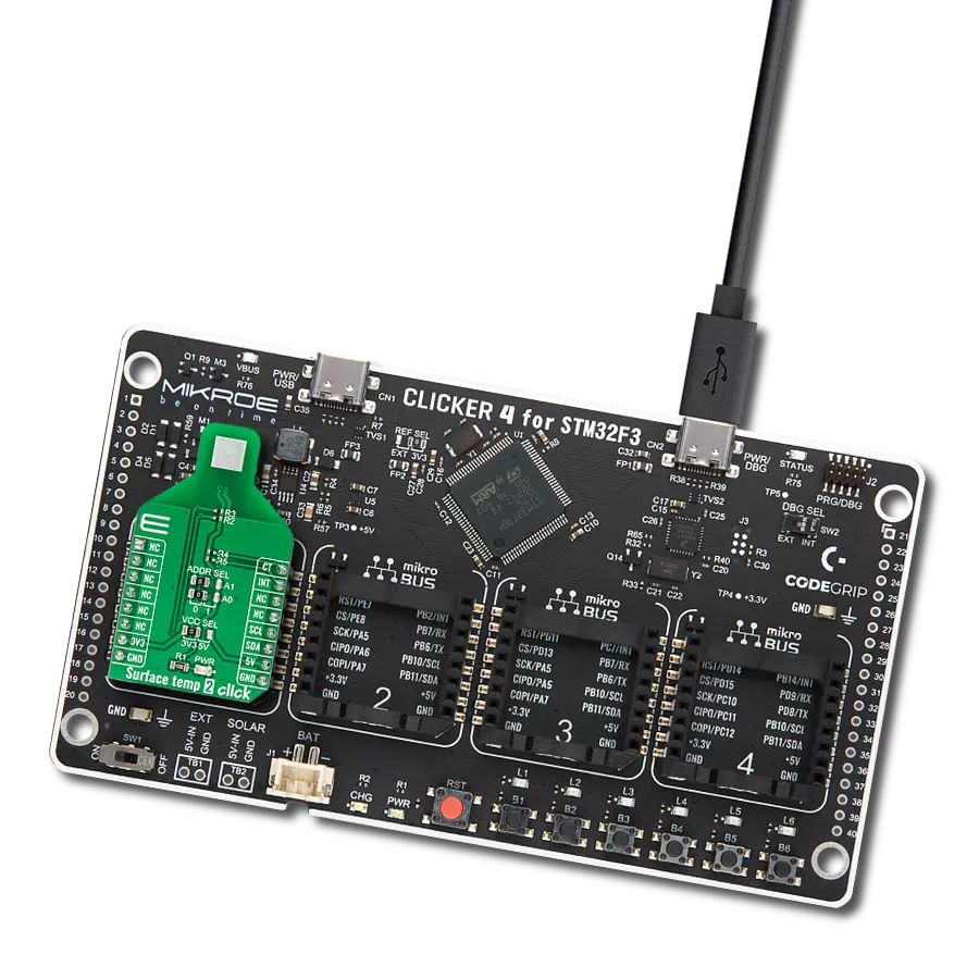
Start by selecting your development board and Click board™. Begin with the Discovery kit with STM32L496AG MCU as your development board.


Track your results in real time
Application Output
1. Application Output - In Debug mode, the 'Application Output' window enables real-time data monitoring, offering direct insight into execution results. Ensure proper data display by configuring the environment correctly using the provided tutorial.

2. UART Terminal - Use the UART Terminal to monitor data transmission via a USB to UART converter, allowing direct communication between the Click board™ and your development system. Configure the baud rate and other serial settings according to your project's requirements to ensure proper functionality. For step-by-step setup instructions, refer to the provided tutorial.

3. Plot Output - The Plot feature offers a powerful way to visualize real-time sensor data, enabling trend analysis, debugging, and comparison of multiple data points. To set it up correctly, follow the provided tutorial, which includes a step-by-step example of using the Plot feature to display Click board™ readings. To use the Plot feature in your code, use the function: plot(*insert_graph_name*, variable_name);. This is a general format, and it is up to the user to replace 'insert_graph_name' with the actual graph name and 'variable_name' with the parameter to be displayed.

Software Support
Library Description
This library contains API for IrThermo Click driver.
Key functions:
irthermo5v_get_t_ambient- Reads Temperature ambient from sensor.irthermo5v_get_t_object- Reads Temperature object from sensor.
Open Source
Code example
The complete application code and a ready-to-use project are available through the NECTO Studio Package Manager for direct installation in the NECTO Studio. The application code can also be found on the MIKROE GitHub account.
/*!
 * @file main.c
 * @brief IrThermo5V Click example
 *
 * # Description
 * This application collects data from the sensor, and logs the results.
 *
 * The demo application is composed of two sections :
 *
 * ## Application Init
 * Initializes IrThermo 5V Driver.
 *
 * ## Application Task
 * Reading Ambient and Object Temperature and displaying the value periodically.
 *
 * @author Stefan Ilic
 *
 */

#include "board.h"
#include "log.h"
#include "irthermo5v.h"

static irthermo5v_t irthermo5v;
static log_t logger;

static float measured_temperature;
static float object_temperature;

void application_init ( void ) {
    log_cfg_t log_cfg;  /**< Logger config object. */
    irthermo5v_cfg_t irthermo5v_cfg;  /**< Click config object. */

    /**
     * Logger initialization.
     * Default baud rate: 115200
     * Default log level: LOG_LEVEL_DEBUG
     * @note If USB_UART_RX and USB_UART_TX
     * are defined as HAL_PIN_NC, you will
     * need to define them manually for log to work.
     * See @b LOG_MAP_USB_UART macro definition for detailed explanation.
     */
    LOG_MAP_USB_UART( log_cfg );
    log_init( &logger, &log_cfg );
    log_info( &logger, " Application Init \r\n " );
    log_printf( &logger, "------------------------------\r\n " );

    // Click initialization.
    irthermo5v_cfg_setup( &irthermo5v_cfg );
    IRTHERMO5V_MAP_MIKROBUS( irthermo5v_cfg, MIKROBUS_1 );
    err_t init_flag = irthermo5v_init( &irthermo5v, &irthermo5v_cfg );
    if ( I2C_MASTER_ERROR == init_flag ) {
        log_error( &logger, " Application Init Error. " );
        log_info( &logger, " Please, run program again... " );

        for ( ; ; );
    }

    log_info( &logger, " Application Task \r\n" );
    log_printf( &logger, "------------------------------\r\n " );
}

void application_task ( void ) {
    measured_temperature = irthermo5v_get_t_ambient( &irthermo5v );
    object_temperature = irthermo5v_get_t_object( &irthermo5v );
    log_printf( &logger, " Ambient Temperature: %.2f C\r\n ", measured_temperature );
    log_printf( &logger, " Object  Temperature: %.2f C\r\n ", object_temperature );
    log_printf( &logger, "------------------------------\r\n " );
    Delay_ms ( 1000 );
}

int main ( void )
{
    /* Do not remove this line or clock might not be set correctly. */
    #ifdef PREINIT_SUPPORTED
    preinit();
    #endif

    application_init( );

    for ( ; ; )
    {
        application_task( );
    }

    return 0;
}

// ------------------------------------------------------------------------ END
Additional Support
Resources
Category:Temperature & humidity