Ensure a stable and regulated output voltage using MPM54304 and PIC18F86K22
Step down voltage with confidence

Published Nov 12, 2023
Click board™
Step Down 6 Click
Dev Board
Fusion for PIC v8
Compiler
NECTO Studio
MCU
PIC18F86K22
Our synchronous step-down DC-DC converter stands as a beacon of efficiency, ensuring precise voltage control and optimal power management for your applications, setting new standards in the industry.
A
A
Hardware Overview
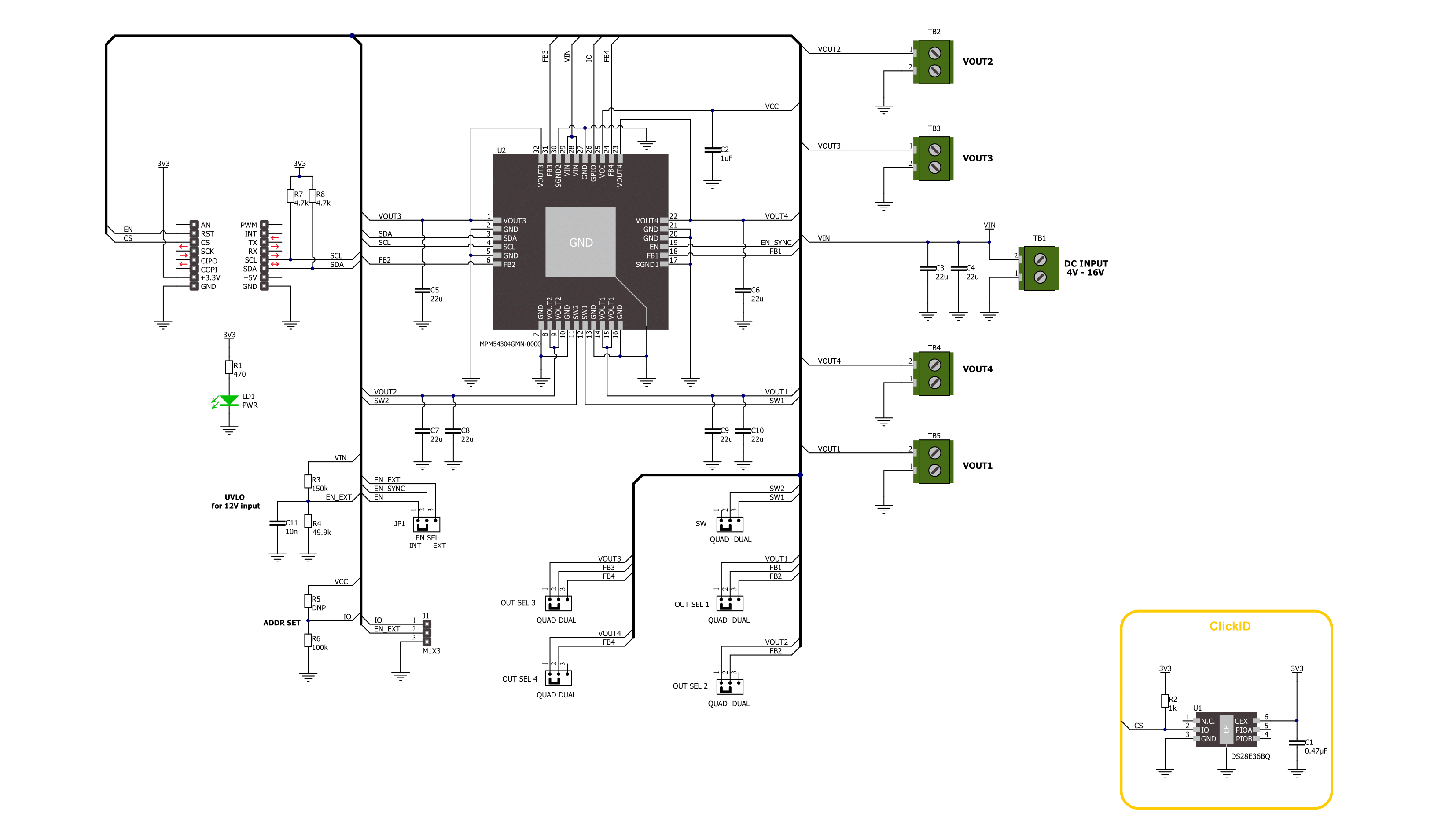
How does it work?
Step Down 6 Click is based on the MPM54304, a quad-output power module from Monolithic Power Systems (MPS). This IC operates over a 4V to 16V input voltage range that can be supplied over the VIN screw terminal. It can step down input voltages as output voltages from 0.55V to 5.4V. The user can choose between straight or parallel output depending on the used output channels, from VOUT1 to VOUT4. Channels VOUT1 and VOUT2 can be paralleled to provide up to 6A of current, and channels VOUT3 and VOUT4 can be paralleled to provide up to 4A of current. The selection between quad and dual channel outputs can be set via the OUT SEL jumpers, where QUAD is selected by default. The user must set all five jumpers into the proper position for the output to work correctly. The MPM54304 has internal auto-compensation, which eliminates the need for an external compensation network, employs a constant-on-time (COT) control scheme to provide ultra-fast load transient responses, and minimizes
the required output capacitance. It also features a two-time, non-volatile programmable memory for storing register settings. Using the host MCU, users can set switching frequency, output voltage, over-current and over-voltage protection thresholds, power-on, power-off sequencing, and Forced PWM or Auto-PWM/PFM. Step Down 6 Click uses a standard 2-Wire I2C interface to communicate with the host MCU, supporting clock frequency up to 3.4MHz and ADDR SET jumper to set the I2C address. In addition to being enabled via the EN pin of the mikroBUS™ socket, the MPM54304 can also be enabled with the appearance of an external power supply by setting the EN SEL jumper to the appropriate position. For that to be done, the EN SEL jumper must be set to the EXT position, thus losing the enable function over the EN pin of the mikroBUS™ socket. The ADDR SET jumper actually uses the GPIO pin of the MPM54304, which can also be used for other purposes, as it is an input/output pin. This
pin can be configured as a Power-Good (PG) pin over the unpopulated IO header that will go to a LOW logic state if any enabled regulator falls below the under-voltage threshold or when all regulators are disabled. It can also be used in the Output Port mode, where it will output corresponding logic depending on the related register. Finally, it can also be used in the SYNCO mode, where it will become the sync output, allowing users to phase-shift the clock output to sync another device’s switching frequency. This Click board™ can be operated only with a 3.3V logic voltage level. The board must perform appropriate logic voltage level conversion before using MCUs with different logic levels. Also, this Click board™ comes equipped with a library containing easy-to-use functions and an example code that can be used as a reference for further development.

Features overview
Development board
Fusion for PIC v8 is a development board specially designed for the needs of rapid development of embedded applications. It supports a wide range of microcontrollers, such as different PIC, dsPIC, PIC24, and PIC32 MCUs regardless of their number of pins, and a broad set of unique functions, such as the first-ever embedded debugger/programmer over WiFi. The development board is well organized and designed so that the end-user has all the necessary elements, such as switches, buttons, indicators, connectors, and others, in one place. Thanks to innovative manufacturing technology, Fusion for PIC v8 provides a fluid and immersive working experience, allowing access anywhere and under any
circumstances at any time. Each part of the Fusion for PIC v8 development board contains the components necessary for the most efficient operation of the same board. In addition to the advanced integrated CODEGRIP programmer/debugger module, which offers many valuable programming/debugging options and seamless integration with the Mikroe software environment, the board also includes a clean and regulated power supply module for the development board. It can use a wide range of external power sources, including a battery, an external 12V power supply, and a power source via the USB Type-C (USB-C) connector. Communication options such as USB-UART, USB
HOST/DEVICE, CAN (on the MCU card, if supported), and Ethernet are also included, including the well-established mikroBUS™ standard, a standardized socket for the MCU card (SiBRAIN standard), and two display options (graphical and character-based LCD). Fusion for PIC v8 is an integral part of the Mikroe ecosystem for rapid development. Natively supported by Mikroe software tools, it covers many aspects of prototyping and development thanks to a considerable number of different Click boards™ (over a thousand boards), the number of which is growing every day.

Microcontroller Overview
MCU Card / MCU
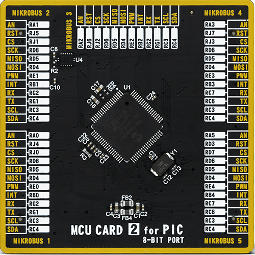
Type
8th Generation
Architecture
PIC
MCU Memory (KB)
64
Silicon Vendor
Microchip
Pin count
80
RAM (Bytes)
3862
Used MCU Pins
mikroBUS™ mapper
Take a closer look
Schematic
Step by step
Project assembly

Start by selecting your development board and Click board™. Begin with the Fusion for PIC v8 as your development board.


Track your results in real time
Application Output
After pressing the "FLASH" button on the left-side panel, it is necessary to open the UART terminal to display the achieved results. By clicking on the Tools icon in the right-hand panel, multiple different functions are displayed, among which is the UART Terminal. Click on the offered "UART Terminal" icon.

Once the UART terminal is opened, the window takes on a new form. At the top of the tab are two buttons, one for adjusting the parameters of the UART terminal and the other for connecting the UART terminal. The tab's lower part is reserved for displaying the achieved results. Before connecting, the terminal has a Disconnected status, indicating that the terminal is not yet active. Before connecting, it is necessary to check the set parameters of the UART terminal. Click on the "OPTIONS" button.

In the newly opened UART Terminal Options field, we check if the terminal settings are correct, such as the set port and the Baud rate of UART communication. If the data is not displayed properly, it is possible that the Baud rate value is not set correctly and needs to be adjusted to 115200. If all the parameters are set correctly, click on "CONFIGURE".

The next step is to click on the "CONNECT" button, after which the terminal status changes from Disconnected to Connected in green, and the data is displayed in the Received data field.

Software Support
Library Description
This library contains API for Step Down 6 Click driver.
Key functions:
stepdown6_set_en_pin- Step Down 6 set EN pin state function.stepdown6_write_reg- Step Down 6 Register writing function.stepdown6_set_out_voltage- Step Down 6 Set output voltage function.
Open Source
Code example
This example can be found in NECTO Studio. Feel free to download the code, or you can copy the code below.
/*!
 * @file main.c
 * @brief Step Down 6 Click example
 *
 * # Description
 * This library contains API for the Step Down 6 Click driver.
 * This driver provides the functions to set the output voltage threshold.
 *
 * The demo application is composed of two sections :
 *
 * ## Application Init
 * Initialization of I2C module and log UART.
 * After driver initialization, default settings sets output voltage to 550 mV.
 *
 * ## Application Task
 * This example demonstrates the use of the Step Down 6 Click board™ by changing
 * output voltage every 5 seconds starting from 550 mV up to 1820 mV.
 *
 * @author Stefan Ilic
 *
 */

#include "board.h"
#include "log.h"
#include "stepdown6.h"

static stepdown6_t stepdown6;
static log_t logger;

void application_init ( void )
{
    log_cfg_t log_cfg;  /**< Logger config object. */
    stepdown6_cfg_t stepdown6_cfg;  /**< Click config object. */

    /**
     * Logger initialization.
     * Default baud rate: 115200
     * Default log level: LOG_LEVEL_DEBUG
     * @note If USB_UART_RX and USB_UART_TX
     * are defined as HAL_PIN_NC, you will
     * need to define them manually for log to work.
     * See @b LOG_MAP_USB_UART macro definition for detailed explanation.
     */
    LOG_MAP_USB_UART( log_cfg );
    log_init( &logger, &log_cfg );
    log_info( &logger, " Application Init " );

    // Click initialization.
    stepdown6_cfg_setup( &stepdown6_cfg );
    STEPDOWN6_MAP_MIKROBUS( stepdown6_cfg, MIKROBUS_1 );
    if ( I2C_MASTER_ERROR == stepdown6_init( &stepdown6, &stepdown6_cfg ) )
    {
        log_error( &logger, " Communication init." );
        for ( ; ; );
    }

    if ( STEPDOWN6_ERROR == stepdown6_default_cfg ( &stepdown6 ) )
    {
        log_error( &logger, " Default configuration." );
        for ( ; ; );
    }
    log_info( &logger, " Application Task " );
}

void application_task ( void )
{
    err_t error_flag = STEPDOWN6_OK;
    for ( uint16_t n_cnt = STEPDOWN6_MIN_VOUT_VAL; n_cnt <= STEPDOWN6_MAX_VOUT_VAL; n_cnt += STEPDOWN6_INCREMENT_VOUT_VAL )
    {
        error_flag |= stepdown6_set_out_voltage( &stepdown6, STEPDOWN6_SELECT_VOUT1, n_cnt );
        error_flag |= stepdown6_set_out_voltage( &stepdown6, STEPDOWN6_SELECT_VOUT2, n_cnt );
        error_flag |= stepdown6_set_out_voltage( &stepdown6, STEPDOWN6_SELECT_VOUT3, n_cnt );
        error_flag |= stepdown6_set_out_voltage( &stepdown6, STEPDOWN6_SELECT_VOUT4, n_cnt );
        log_printf( &logger, "  Set voltage : %d mV \r\n", n_cnt );
        Delay_ms( 5000 );
    }
}

void main ( void )
{
    application_init( );

    for ( ; ; )
    {
        application_task( );
    }
}

// ------------------------------------------------------------------------ END


