NH3 monitoring made simple with MQ-137 and TM4C129ENCPDT
Guardians of purity: Innovating ammonia sensing solution
Published Aug 29, 2023
Click board™
Ammonia Click
Dev. board
Fusion for Tiva v8
Compiler
NECTO Studio
MCU
TM4C129ENCPDT
Our ammonia sensing solution provides accurate and timely information, enabling industries and communities to manage ammonia levels and maintain safe, breathable air
A
A
Hardware Overview
How does it work?
Ammonia Click is based on the MQ-137 gas sensor from Winsen, which uses the SnO2 (tin-oxide) alloy, which decreases its resistance while exposed to the NH3 gas. The greater the NH3 concentration is, the more conductive this material becomes. This can be utilized to obtain the NH3 concentration readings. The sensor contains a small heating element connected to a 5V power supply. The heater element can be controlled via a MOSFET power switch connected to the PWM pin on the mikroBUS™ socket for lower power consumption. It needs to be preheated for a minimum of 24 hours before it can perform as specified. A stainless mesh protects The sensor against particles and mechanical damage; however, exposure to excessive moisture and corrosive gases can damage the inner structure. The measuring circuit consists of the MQ-137 sensor, a power source, and a load resistor (RL) between the output pin and GND. With its internal
resistance, the sensor forms a voltage divider with the load resistor. The RL is designed as a variable resistor, allowing the output voltage to be trimmed to the desired value. The calibration should be performed in controlled conditions, as the ambient temperature and humidity affect the sensor's resistance. The sensor can measure relative NH3 concentration change without accurate calibration, which is useful for building applications that can be used as warning systems. The middle tap of the sensor RL voltage divider is routed to an SMD jumper labeled ADC SEL. This jumper can redirect the measuring voltage to the ADC for sampling or the AN pin so that it can be used in an external circuitry (external ADC or some other form of measurement signal conditioning). The MCP3551, a 22-bit sigma-delta ADC from Microchip, is used to sample the sensor output when selected by the ADC SEL jumper. This ADC converts the input voltage, with a very high
resolution of 22 bits and low noise, to digital data, which can be obtained via the SPI interface of the Click board™. This ADC uses the reference voltage, which is the same as the power supply voltage, and in this case, it is powered by 5V from the mikroBUS™ power rail. As already mentioned, the ADC uses a 5V power supply. Therefore, this board needs a level conversion circuitry interfacing with 3.3V MCUs. This Click board™ uses the TXB0106 IC, a 6-bit bidirectional level shifting IC from Texas Instruments, which is used to shift communication logic voltage levels from 5V to 3.3V. This Click board™ can operate with either 3.3V or 5V logic voltage levels selected via the VCC SEL jumper. This way, both 3.3V and 5V capable MCUs can use the communication lines properly. Also, this Click board™ comes equipped with a library containing easy-to-use functions and an example code that can be used as a reference for further development.


Features overview
Development board
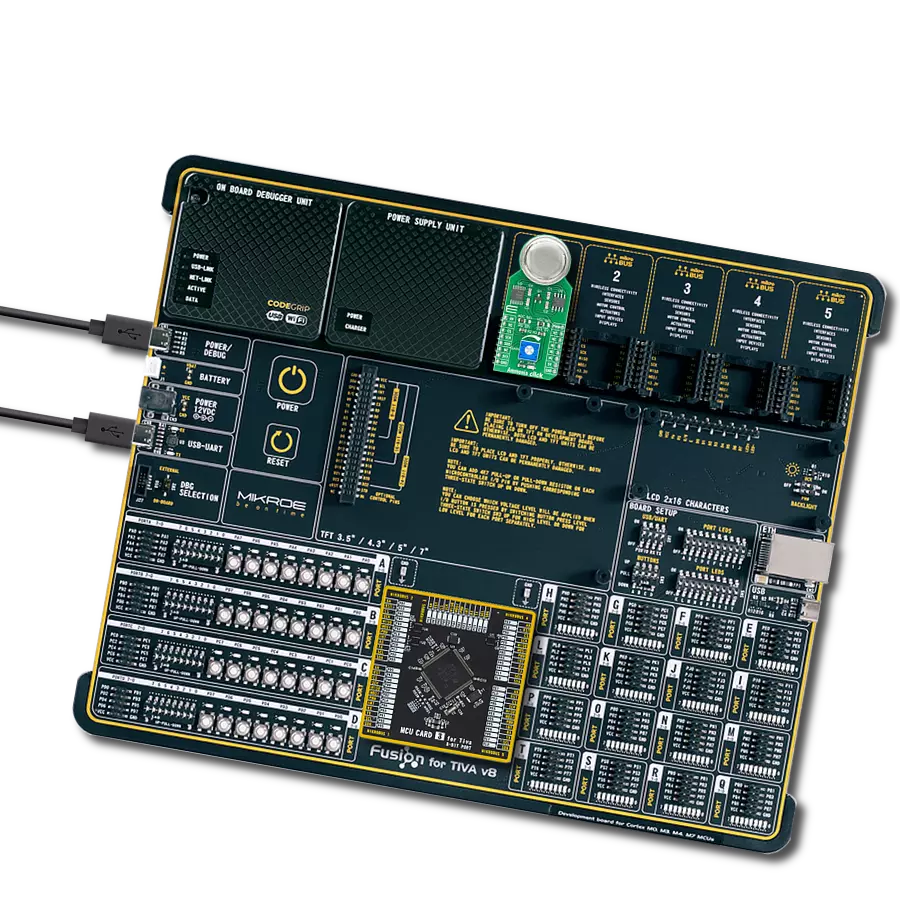
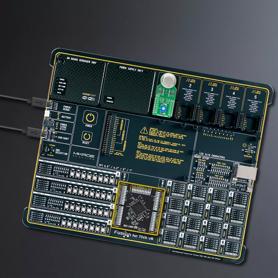
Fusion for TIVA v8 is a development board specially designed for the needs of rapid development of embedded applications. It supports a wide range of microcontrollers, such as different 32-bit ARM® Cortex®-M based MCUs from Texas Instruments, regardless of their number of pins, and a broad set of unique functions, such as the first-ever embedded debugger/programmer over a WiFi network. The development board is well organized and designed so that the end-user has all the necessary elements, such as switches, buttons, indicators, connectors, and others, in one place. Thanks to innovative manufacturing technology, Fusion for TIVA v8 provides a fluid and immersive working experience, allowing access
anywhere and under any circumstances at any time. Each part of the Fusion for TIVA v8 development board contains the components necessary for the most efficient operation of the same board. An advanced integrated CODEGRIP programmer/debugger module offers many valuable programming/debugging options, including support for JTAG, SWD, and SWO Trace (Single Wire Output)), and seamless integration with the Mikroe software environment. Besides, it also includes a clean and regulated power supply module for the development board. It can use a wide range of external power sources, including a battery, an external 12V power supply, and a power source via the USB Type-C (USB-C) connector.
Communication options such as USB-UART, USB HOST/DEVICE, CAN (on the MCU card, if supported), and Ethernet is also included. In addition, it also has the well-established mikroBUS™ standard, a standardized socket for the MCU card (SiBRAIN standard), and two display options for the TFT board line of products and character-based LCD. Fusion for TIVA v8 is an integral part of the Mikroe ecosystem for rapid development. Natively supported by Mikroe software tools, it covers many aspects of prototyping and development thanks to a considerable number of different Click boards™ (over a thousand boards), the number of which is growing every day.

Microcontroller Overview
MCU Card / MCU

Type
8th Generation
Architecture
ARM Cortex-M4
MCU Memory (KB)
1024
Silicon Vendor
Texas Instruments
Pin count
128
RAM (Bytes)
262144
Used MCU Pins
mikroBUS™ mapper
Take a closer look
Click board™ Schematic

Step by step
Project assembly

Start by selecting your development board and Click board™. Begin with the Fusion for Tiva v8 as your development board.


Software Support
Library Description
This library contains API for Ammonia Click driver.
Key functions:
ammonia_heater- Sensor heater functionammonia_data_read- Read data function
Open Source
Code example
The complete application code and a ready-to-use project are available through the NECTO Studio Package Manager for direct installation in the NECTO Studio. The application code can also be found on the MIKROE GitHub account.
/*!
 * \file
 * \brief Ammonia Click example
 *
 * # Description
 * This example shows the value of ammonia measurement aquired from Ammonia Click board.
 *
 * The demo application is composed of two sections :
 *
 * ## Application Init
 * Calls functions for driver initializaton used for data conversion and results reading.
 *
 * ## Application Task
 * Reads the level of ammonia in the air every with repetition of 1 second.
 * This driver is able to get the level of ammonia gas in the range from 5 to 200 ppm.
 * #note#
 * Be sure that you correctly set the AD convertor which you want to use.
 *
 * \author Nemanja Medakovic
 *
 */
// ------------------------------------------------------------------- INCLUDES

#include "board.h"
#include "log.h"
#include "ammonia.h"

// ------------------------------------------------------------------ VARIABLES

static ammonia_t ammonia;
static log_t logger;

// ------------------------------------------------------ APPLICATION FUNCTIONS

void application_init ( void )
{
    log_cfg_t log_cfg;

    /**
     * Logger initialization.
     * Default baud rate: 115200
     * Default log level: LOG_LEVEL_DEBUG
     * @note If USB_UART_RX and USB_UART_TX
     * are defined as HAL_PIN_NC, you will
     * need to define them manually for log to work.
     * See @b LOG_MAP_USB_UART macro definition for detailed explanation.
     */
    LOG_MAP_USB_UART( log_cfg );
    log_init( &logger, &log_cfg );
    log_info( &logger, "---- Application Init... ----" );

    ammonia_cfg_t ammonia_cfg;

    //  Click initialization.

    ammonia_cfg_setup( &ammonia_cfg );
    AMMONIA_MAP_MIKROBUS( ammonia_cfg, MIKROBUS_1 );

    if ( ammonia_init( &ammonia, &ammonia_cfg ) == AMMONIA_INIT_ERROR )
    {
        log_info( &logger, "---- Application Init Error. ----" );
        log_info( &logger, "---- Please, run program again... ----" );

        for ( ; ; );
    }

    log_info( &logger, "---- Application Init Done. ----\n" );
}

void application_task ( void )
{
    uint16_t nh3_ppm;

    if ( ammonia_read_measurement( &ammonia, &nh3_ppm ) == AMMONIA_OK )
    {
        log_printf( &logger, "  NH3 [ppm] : %u\r\n", nh3_ppm );
        Delay_ms ( 1000 );
    }
}

int main ( void )
{
    /* Do not remove this line or clock might not be set correctly. */
    #ifdef PREINIT_SUPPORTED
    preinit();
    #endif

    application_init( );

    for ( ; ; )
    {
        application_task( );
    }

    return 0;
}

// ------------------------------------------------------------------------ END


