Ensure safe operation of pressure-sensitive systems with MS5637-02BA03 and TM4C129ENCPDT
From bar to byte
Published Oct 14, 2023
Click board™
Barometer 5 Click
Dev. board
Fusion for Tiva v8
Compiler
NECTO Studio
MCU
TM4C129ENCPDT
In various industrial settings, this solution is employed to monitor and regulate atmospheric conditions, guaranteeing that processes and experiments are carried out under stable pressure conditions
A
A
Hardware Overview
How does it work?
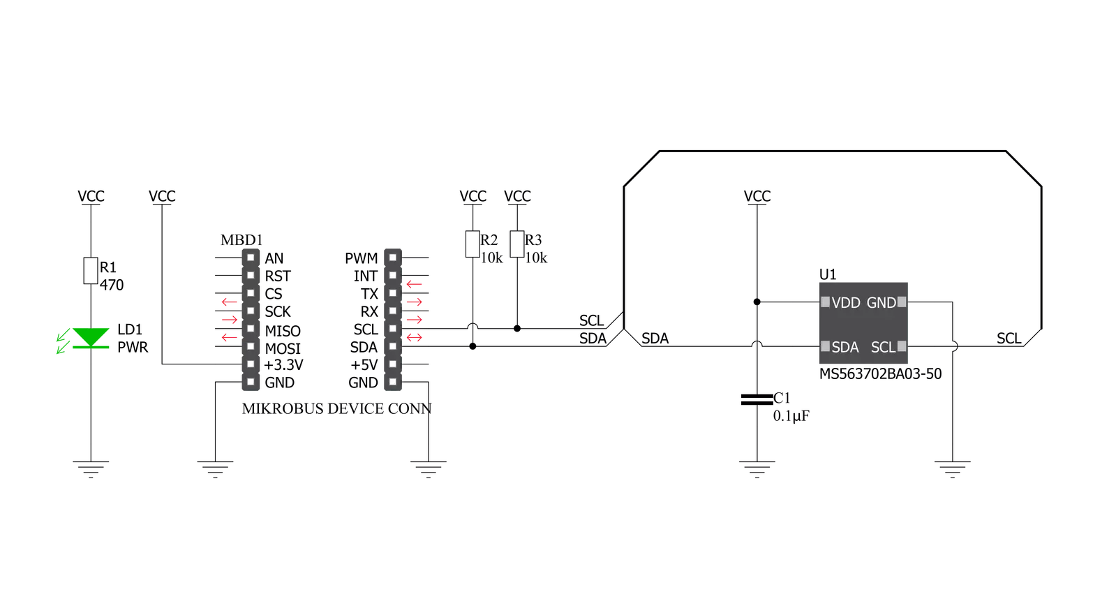
Barometer 5 Click is based on the MS5637-02BA03, a high accuracy low voltage barometric and temperature sensor from TE Connectivity Measurement Specialties, to measure air pressure in a specific environment. This new sensor module generation is based on leading MEMS technology, where the sensing principle leads to very low hysteresis and high pressure and temperature signal stability. It consists of a piezoresistive sensor and a sensor interface integrated circuit. The primary function of the MS5637-02BA03 is to convert and provide the uncompensated analog output voltage from the piezoresistive pressure sensor to a 24-bit digital value for the sensor's temperature. It can measure pressure from 300mbar up to 1.2bar with an accuracy of ±2mbar over a wide operating temperature range at the
industry's lowest power. As mentioned, the MS5637-02BA03 has integrated ultra-low-power 24-bit ΔΣ ADC with internal factory-calibrated coefficients, which, alongside precise pressure value, also provides temperature value. A high-resolution temperature output allows the implementation of an altimeter/thermometer function without any additional sensor, with an altitude resolution at sea level of 13cm of air. Barometer 5 Click communicates with MCU using the standard I2C 2-Wire interface to read data and configure settings, supporting Standard Mode operation with a clock frequency of 100kHz and Fast Mode up to 400kHz. Besides, it also offers different operation modes, allowing the user to optimize for conversion speed and current consumption. Suppose the user decides not to use
our compliant library but to do software development independently. In that case, it is recommended to compensate for the non-linearity over the temperature to obtain the best accuracy over the temperature range, particularly at low temperatures. This can be achieved by correcting the calculated temperature, offset, and sensitivity by a second-order correction factor. This Click board™ can be operated only with a 3.3V logic voltage level. The board must perform appropriate logic voltage level conversion before using MCUs with different logic levels. Also, it comes equipped with a library containing functions and an example code that can be used as a reference for further development.


Features overview
Development board
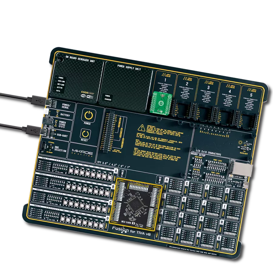
Fusion for TIVA v8 is a development board specially designed for the needs of rapid development of embedded applications. It supports a wide range of microcontrollers, such as different 32-bit ARM® Cortex®-M based MCUs from Texas Instruments, regardless of their number of pins, and a broad set of unique functions, such as the first-ever embedded debugger/programmer over a WiFi network. The development board is well organized and designed so that the end-user has all the necessary elements, such as switches, buttons, indicators, connectors, and others, in one place. Thanks to innovative manufacturing technology, Fusion for TIVA v8 provides a fluid and immersive working experience, allowing access
anywhere and under any circumstances at any time. Each part of the Fusion for TIVA v8 development board contains the components necessary for the most efficient operation of the same board. An advanced integrated CODEGRIP programmer/debugger module offers many valuable programming/debugging options, including support for JTAG, SWD, and SWO Trace (Single Wire Output)), and seamless integration with the Mikroe software environment. Besides, it also includes a clean and regulated power supply module for the development board. It can use a wide range of external power sources, including a battery, an external 12V power supply, and a power source via the USB Type-C (USB-C) connector.
Communication options such as USB-UART, USB HOST/DEVICE, CAN (on the MCU card, if supported), and Ethernet is also included. In addition, it also has the well-established mikroBUS™ standard, a standardized socket for the MCU card (SiBRAIN standard), and two display options for the TFT board line of products and character-based LCD. Fusion for TIVA v8 is an integral part of the Mikroe ecosystem for rapid development. Natively supported by Mikroe software tools, it covers many aspects of prototyping and development thanks to a considerable number of different Click boards™ (over a thousand boards), the number of which is growing every day.

Microcontroller Overview
MCU Card / MCU

Type
8th Generation
Architecture
ARM Cortex-M4
MCU Memory (KB)
1024
Silicon Vendor
Texas Instruments
Pin count
128
RAM (Bytes)
262144
Used MCU Pins
mikroBUS™ mapper
Take a closer look
Click board™ Schematic
Step by step
Project assembly

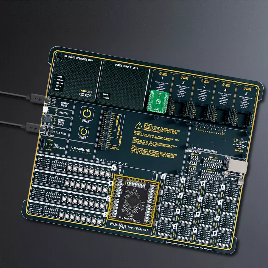
Start by selecting your development board and Click board™. Begin with the Fusion for Tiva v8 as your development board.


Software Support
Library Description
This library contains API for Barometer 5 Click driver.
Key functions:
barometer5_get_data- Barometer 5 get data functionbarometer5_get_pressure- Barometer 5 get pressure data functionbarometer5_get_temperature- Barometer 5 get temperature data function
Open Source
Code example
The complete application code and a ready-to-use project are available through the NECTO Studio Package Manager for direct installation in the NECTO Studio. The application code can also be found on the MIKROE GitHub account.
/*!
 * @file main.c
 * @brief Barometer5 Click example
 *
 * # Description
 * This library contains API for Barometer 5 Click driver.
 * The demo application reads and calculate temperature and pressure data.
 *
 * The demo application is composed of two sections :
 *
 * ## Application Init
 * Initializes I2C driver and log UART.
 * After driver initialization the app set default settings.
 *
 * ## Application Task
 * This is an example that demonstrates the use of the Barometer 5 Click board™.
 * In this example, display the Pressure ( mBar ) and Temperature ( degree Celsius ) data.
 * Results are being sent to the Usart Terminal where you can track their changes.
 *
 * @author Nenad Filipovic
 *
 */

#include "board.h"
#include "log.h"
#include "barometer5.h"

static barometer5_t barometer5;
static log_t logger;

void application_init ( void )
{
    log_cfg_t log_cfg;  /**< Logger config object. */
    barometer5_cfg_t barometer5_cfg;  /**< Click config object. */

    /**
     * Logger initialization.
     * Default baud rate: 115200
     * Default log level: LOG_LEVEL_DEBUG
     * @note If USB_UART_RX and USB_UART_TX
     * are defined as HAL_PIN_NC, you will
     * need to define them manually for log to work.
     * See @b LOG_MAP_USB_UART macro definition for detailed explanation.
     */
    LOG_MAP_USB_UART( log_cfg );
    log_init( &logger, &log_cfg );
    log_info( &logger, " Application Init " );

    // Click initialization.
    barometer5_cfg_setup( &barometer5_cfg );
    BAROMETER5_MAP_MIKROBUS( barometer5_cfg, MIKROBUS_1 );
    if ( I2C_MASTER_ERROR == barometer5_init( &barometer5, &barometer5_cfg ) )
    {
        log_error( &logger, " Communication init." );
        for ( ; ; );
    }

    if ( BAROMETER5_ERROR == barometer5_default_cfg ( &barometer5 ) )
    {
        log_error( &logger, " Default configuration." );
        for ( ; ; );
    }

    log_info( &logger, " Application Task " );
    log_printf( &logger, "---------------------------\r\n" );
    Delay_ms ( 100 );
}

void application_task ( void )
{
    static float temperature;
    static float pressure;

    if ( barometer5_get_data( &barometer5, &temperature, &pressure ) == BAROMETER5_OK )
    {
        log_printf( &logger, " Pressure    : %.2f mbar   \r\n", pressure );
        log_printf( &logger, " Temperature : %.2f C      \r\n", temperature );
        log_printf( &logger, "---------------------------\r\n" );
    }

    Delay_ms ( 1000 );
}

int main ( void )
{
    /* Do not remove this line or clock might not be set correctly. */
    #ifdef PREINIT_SUPPORTED
    preinit();
    #endif

    application_init( );

    for ( ; ; )
    {
        application_task( );
    }

    return 0;
}

// ------------------------------------------------------------------------ END
Additional Support
Resources
Category:Pressure


