Ensures your signals are channeled precisely using MUX508 and STM32L496AG
Redefine connectivity with CMOS analog mux

Published Jul 22, 2025
Click board™
MUX 2 click
Dev. board
Discovery kit with STM32L496AG MCU
Compiler
NECTO Studio
MCU
STM32L496AG
Tailored for various applications, it enables you to seamlessly control and direct analog signals, opening doors to enhanced connectivity and data management
A
A
Hardware Overview
How does it work?
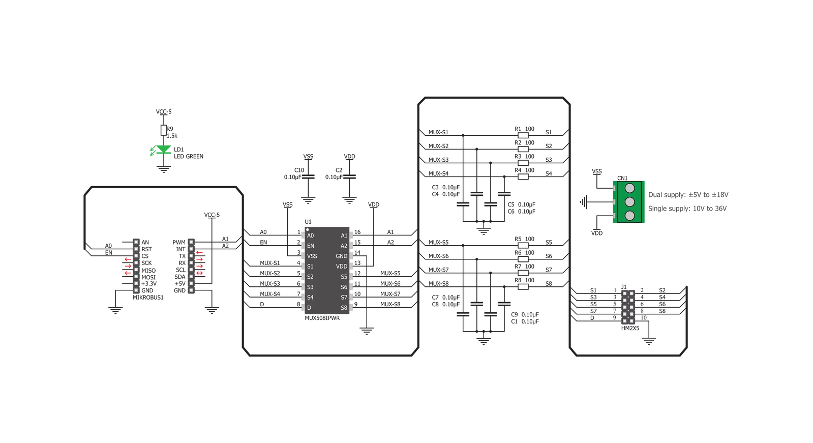
MUX 2 Click is based on the MUX508, a precise analog multiplexing from Texas Instruments. The MUX508 can be used with a wide range of power supplies. It can handle dual and single power supplies and symmetrical and non-symmetrical ones. This allows it to be used in a wide range of different applications. Four control pins switch one of eight inputs to a single output. Control pins labeled A0, A1, and A2 are routed to the mikroBUS™ and can be operated by both 3.3V and 5V MCUs. The fourth control pin, labeled as EN pin, is used to enable the internal multiplexing switches of the IC when set to a HIGH logic level (active HIGH). A0, A1, and A2 pins are routed to the RST, PWM, and INT pins of the mikroBUS™, respectively, while the EN pin is routed to the CS pin on the mikroBUS™. The MUX508 is targeted toward working with both bipolar and unipolar
single-ended inputs. Each input is labeled S1 to S8. When a specific channel is selected using the A0 to A2 pins, it will be switched to the output pin, labeled as D. For improved stability, each pin is equipped with the 100nF parallel capacitor and 100Ω series resistance. The input and the output signal pins are routed to the standard 2.54mm pitch 2x5 pins header on the Click board™. The ultra-low leakage current ensures no signal interference from the inputs that the A0, A1, and A2 pins do not select. Low crosstalk also ensures that the signal on one channel remains clean of interferences caused by other channels. A break-before-make switching action is utilized to prevent any two inputs from being switched at the output simultaneously. This ensures the reliable operation of the IC and the Click board™ itself. MUX 2 Click does not use the power from the mikroBUS™
power rails, except for the LED indicator. Instead, a three-pole screw terminal connects an external power supply. Considering the minimum input voltage of 10V or ±5V, a power supply should be connected to this terminal before operating the Click board™. The input and output signals can be connected via the 2x5 pins header. As mentioned before, the MUX508 IC supports rail-to-rail operation. Independent power supply input allows the user to work with a wide range of signal amplitudes, depending on the application requirements, as long as the power supply stays within limits. More information about the MUX508 can be found in the attached datasheet. Also, this Click board™ comes equipped with a library containing easy-to-use functions and an example code that can be used, as a reference, for further development.

Features overview
Development board
The 32L496GDISCOVERY Discovery kit serves as a comprehensive demonstration and development platform for the STM32L496AG microcontroller, featuring an Arm® Cortex®-M4 core. Designed for applications that demand a balance of high performance, advanced graphics, and ultra-low power consumption, this kit enables seamless prototyping for a wide range of embedded solutions. With its innovative energy-efficient
architecture, the STM32L496AG integrates extended RAM and the Chrom-ART Accelerator, enhancing graphics performance while maintaining low power consumption. This makes the kit particularly well-suited for applications involving audio processing, graphical user interfaces, and real-time data acquisition, where energy efficiency is a key requirement. For ease of development, the board includes an onboard ST-LINK/V2-1
debugger/programmer, providing a seamless out-of-the-box experience for loading, debugging, and testing applications without requiring additional hardware. The combination of low power features, enhanced memory capabilities, and built-in debugging tools makes the 32L496GDISCOVERY kit an ideal choice for prototyping advanced embedded systems with state-of-the-art energy efficiency.

Microcontroller Overview
MCU Card / MCU

Architecture
ARM Cortex-M4
MCU Memory (KB)
1024
Silicon Vendor
STMicroelectronics
Pin count
169
RAM (Bytes)
327680
Used MCU Pins
mikroBUS™ mapper
Take a closer look
Click board™ Schematic
Step by step
Project assembly

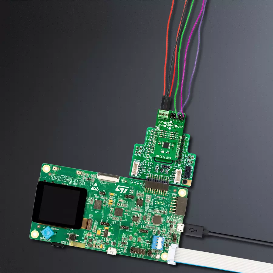
Start by selecting your development board and Click board™. Begin with the Discovery kit with STM32L496AG MCU as your development board.


Track your results in real time
Application Output
1. Application Output - In Debug mode, the 'Application Output' window enables real-time data monitoring, offering direct insight into execution results. Ensure proper data display by configuring the environment correctly using the provided tutorial.

2. UART Terminal - Use the UART Terminal to monitor data transmission via a USB to UART converter, allowing direct communication between the Click board™ and your development system. Configure the baud rate and other serial settings according to your project's requirements to ensure proper functionality. For step-by-step setup instructions, refer to the provided tutorial.

3. Plot Output - The Plot feature offers a powerful way to visualize real-time sensor data, enabling trend analysis, debugging, and comparison of multiple data points. To set it up correctly, follow the provided tutorial, which includes a step-by-step example of using the Plot feature to display Click board™ readings. To use the Plot feature in your code, use the function: plot(*insert_graph_name*, variable_name);. This is a general format, and it is up to the user to replace 'insert_graph_name' with the actual graph name and 'variable_name' with the parameter to be displayed.

Software Support
Library Description
This library contains API for MUX 2 Click driver.
Key functions:
mux2_active_mux_channel- Select active MUX channelmux2_device_disable- Enable MUX device functionmux2_device_enable- Disable MUX device function.
Open Source
Code example
The complete application code and a ready-to-use project are available through the NECTO Studio Package Manager for direct installation in the NECTO Studio. The application code can also be found on the MIKROE GitHub account.
/*!
 * \file
 * \brief MUX 2 Click example
 *
 * # Description
 * Sets the current active channel. Changes the channel every 5 sec.
 *
 * The demo application is composed of two sections :
 *
 * ## Application Init
 * Initializes GPIO module and sets RST, CS, PWM and INT pins as OUTPUT.
 *
 * ## Application Task
 * Changes currently active channel every 5 sec.
 *
 * \author Luka Filipovic
 *
 */
// ------------------------------------------------------------------- INCLUDES

#include "board.h"
#include "log.h"
#include "mux2.h"

// ------------------------------------------------------------------ VARIABLES

static mux2_t mux2;
static log_t logger;

// ------------------------------------------------------ APPLICATION FUNCTIONS

void application_init ( void )
{
    log_cfg_t log_cfg;
    mux2_cfg_t cfg;

    /**
     * Logger initialization.
     * Default baud rate: 115200
     * Default log level: LOG_LEVEL_DEBUG
     * @note If USB_UART_RX and USB_UART_TX
     * are defined as HAL_PIN_NC, you will
     * need to define them manually for log to work.
     * See @b LOG_MAP_USB_UART macro definition for detailed explanation.
     */
    LOG_MAP_USB_UART( log_cfg );
    log_init( &logger, &log_cfg );
    log_info(&logger, "---- Application Init ----");

    //  Click initialization.

    mux2_cfg_setup( &cfg );
    MUX2_MAP_MIKROBUS( cfg, MIKROBUS_1 );
    mux2_init( &mux2, &cfg );
    Delay_ms ( 100 );

    log_printf( &logger, "       MUX 2 Click\r\n" );
    log_printf( &logger, "------------------------\r\n" );

    mux2_device_enable( &mux2 );
    log_printf( &logger, "    Enable MUX device\r\n" );
    log_printf( &logger, "------------------------\r\n" );
    Delay_ms ( 100 );
}

void application_task ( void )
{
    uint8_t n_cnt;

    //  Task implementation.

    for ( n_cnt = MUX2_CHANNEL_S1; n_cnt < MUX2_CHANNEL_END; n_cnt++ )
    {
        log_printf( &logger, "      CHANNEL  S%d\r\n", ( uint16_t )n_cnt );
        log_printf( &logger, "------------------------\r\n" );

        mux2_active_mux_channel( &mux2, n_cnt );
        Delay_ms ( 1000 );
        Delay_ms ( 1000 );
        Delay_ms ( 1000 );
        Delay_ms ( 1000 );
        Delay_ms ( 1000 );
    }
}

int main ( void )
{
    /* Do not remove this line or clock might not be set correctly. */
    #ifdef PREINIT_SUPPORTED
    preinit();
    #endif

    application_init( );

    for ( ; ; )
    {
        application_task( );
    }

    return 0;
}


// ------------------------------------------------------------------------ END
Additional Support
Resources
Category:DAC


