Bring your creative vision to life with PCA9745B and STM32L496AG
Crafting colorful moments: RGBA LED control simplified!

Published Jul 22, 2025
Click board™
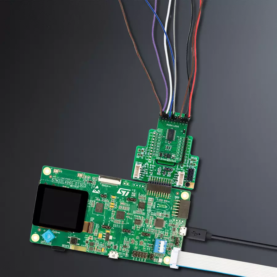
LED Driver 16 Click
Dev. board
Discovery kit with STM32L496AG MCU
Compiler
NECTO Studio
MCU
STM32L496AG
Our cutting-edge LED driver solution offers simplified control for dimming and blinking RGBA LEDs, allowing you to create dynamic lighting effects effortlessly and customize your ambiance
A
A
Hardware Overview
How does it work?
LED Driver 16 Click is based on the PCA9745B, a daisy-chain SPI-compatible 16-channel constant current LED driver from NXP Semiconductors. The PCA9745B provides a maximum output current of 57mA per channel (set through an onboard R6 resistor), making it suitable for dimming and blinking Red/Green/Blue/Amber (RGBA) LEDs. Each of the 16 LED outputs has its 8-bit resolution (256 steps) fixed-frequency individual PWM controller, operating at 31.25 kHz with an adjustable duty cycle. The duty cycle goes from 0% to 100%, allowing LEDs to be set to a specific brightness value; either dim or blink all LEDs with the same value. Gradation control for all current sources is achieved through serial interface and 8-bit DACs, allowing users to ramp current automatically, without MCU intervention, and thus
adjust brightness levels for each LED current source. There are four selectable gradation control groups, and each group has independently four registers to control ramp-up and ramp-down rate, step time, hold ON/OFF time, and final hold ON output current. Two gradation operation modes are available for each group: single shot mode (output pattern once) and continuous mode (output pattern repeat). LED Driver 16 Click communicates with MCU through a register-selectable standard SPI interface that enables high clock speed up to 25MHz for optimum performance, supporting the most common SPI mode, SPI Mode 0. In addition to the SPI interface signals, this board uses several other signals from the mikroBUS™ socket. The reset pin routed on the RST pin of the mikroBUS™ socket provides the
general reset ability, while the OE pin of the mikroBUS™ socket, hence, offers a switch operation (enabled/disabled) to turn ON/OFF power delivery to the PCA9745B. The OE pin can also be used as an external dimming control signal. In that case, the external clock frequency must be very high, more precisely unseen by the human eye, and the duty cycle value determines the brightness of the LEDs. This Click board™ can operate with either 3.3V or 5V logic voltage levels selected via the VCC SEL jumper. This way, both 3.3V and 5V capable MCUs can use the communication lines properly. Also, this Click board™ comes equipped with a library containing easy-to-use functions and an example code that can be used as a reference for further development.


Features overview
Development board
The 32L496GDISCOVERY Discovery kit serves as a comprehensive demonstration and development platform for the STM32L496AG microcontroller, featuring an Arm® Cortex®-M4 core. Designed for applications that demand a balance of high performance, advanced graphics, and ultra-low power consumption, this kit enables seamless prototyping for a wide range of embedded solutions. With its innovative energy-efficient
architecture, the STM32L496AG integrates extended RAM and the Chrom-ART Accelerator, enhancing graphics performance while maintaining low power consumption. This makes the kit particularly well-suited for applications involving audio processing, graphical user interfaces, and real-time data acquisition, where energy efficiency is a key requirement. For ease of development, the board includes an onboard ST-LINK/V2-1
debugger/programmer, providing a seamless out-of-the-box experience for loading, debugging, and testing applications without requiring additional hardware. The combination of low power features, enhanced memory capabilities, and built-in debugging tools makes the 32L496GDISCOVERY kit an ideal choice for prototyping advanced embedded systems with state-of-the-art energy efficiency.

Microcontroller Overview
MCU Card / MCU

Architecture
ARM Cortex-M4
MCU Memory (KB)
1024
Silicon Vendor
STMicroelectronics
Pin count
169
RAM (Bytes)
327680
Used MCU Pins
mikroBUS™ mapper
Take a closer look
Click board™ Schematic

Step by step
Project assembly

Start by selecting your development board and Click board™. Begin with the Discovery kit with STM32L496AG MCU as your development board.


Software Support
Library Description
This library contains API for LED Driver 16 Click driver.
Key functions:
leddriver16_set_led_state- This function sets the output state for the specified LEDsleddriver16_set_led_pwm- This function sets the PWM duty cycle for the specified LEDsleddriver16_set_led_iref- This function sets the gain settings for output current for the specified LEDs
Open Source
Code example
The complete application code and a ready-to-use project are available through the NECTO Studio Package Manager for direct installation in the NECTO Studio. The application code can also be found on the MIKROE GitHub account.
/*!
 * @file main.c
 * @brief LED Driver 16 Click example
 *
 * # Description
 * This example demonstrates the use of LED Driver 16 Click board by performing
 * 3 different types of LED control (LED PWM dimming, LED blinking, and LED curtain).
 *
 * The demo application is composed of two sections :
 *
 * ## Application Init
 * Initializes the driver and performs the Click default configuration.
 *
 * ## Application Task
 * Performs 3 different types of LED control examples. Each example repeats 5 times before
 * switching to another. The name of the currently set example will be displayed on the USB UART accordingly.
 * - Example 1:
 * LED PWM dimming - starts with min PWM duty cycle and increases it to max, then decreases
 * it to min duty cycle in a loop with a 5ms delay on duty change.
 * - Example 2:
 * LED blinking - toggles all LEDs state from ON to OFF and vice-versa with a 500ms delay in between.
 * - Example 3:
 * LED curtain - turns ON the LEDs one by one from LED0 to LED15 with a 100ms delay on transition
 * to the next LED.
 *
 * @author Stefan Filipovic
 *
 */

#include "board.h"
#include "log.h"
#include "leddriver16.h"

static leddriver16_t leddriver16;
static log_t logger;

void application_init ( void )
{
    log_cfg_t log_cfg;  /**< Logger config object. */
    leddriver16_cfg_t leddriver16_cfg;  /**< Click config object. */

    /**
     * Logger initialization.
     * Default baud rate: 115200
     * Default log level: LOG_LEVEL_DEBUG
     * @note If USB_UART_RX and USB_UART_TX
     * are defined as HAL_PIN_NC, you will
     * need to define them manually for log to work.
     * See @b LOG_MAP_USB_UART macro definition for detailed explanation.
     */
    LOG_MAP_USB_UART( log_cfg );
    log_init( &logger, &log_cfg );
    log_info( &logger, " Application Init " );

    // Click initialization.
    leddriver16_cfg_setup( &leddriver16_cfg );
    LEDDRIVER16_MAP_MIKROBUS( leddriver16_cfg, MIKROBUS_1 );
    if ( SPI_MASTER_ERROR == leddriver16_init( &leddriver16, &leddriver16_cfg ) )
    {
        log_error( &logger, " Communication init." );
        for ( ; ; );
    }

    if ( LEDDRIVER16_ERROR == leddriver16_default_cfg ( &leddriver16 ) )
    {
        log_error( &logger, " Default configuration." );
        for ( ; ; );
    }

    log_info( &logger, " Application Task " );
}

void application_task ( void )
{
    static uint8_t example_repeat_num = 5;
    uint8_t repeat_cnt = 0;
    log_printf( &logger, " LED PWM dimming\r\n\n" );
    leddriver16_set_led_state ( &leddriver16, LEDDRIVER16_LED_CHANNEL_ALL, LEDDRIVER16_LEDOUT_PWM_ALL );
    while ( repeat_cnt < example_repeat_num )
    {
        uint8_t pwm_duty = LEDDRIVER16_PWM_DUTY_MIN;
        while ( pwm_duty < LEDDRIVER16_PWM_DUTY_MAX )
        {
            leddriver16_set_led_pwm ( &leddriver16, LEDDRIVER16_LED_CHANNEL_ALL, pwm_duty );
            Delay_ms ( 5 );
            pwm_duty++;
        }
        while ( pwm_duty > LEDDRIVER16_PWM_DUTY_MIN )
        {
            leddriver16_set_led_pwm ( &leddriver16, LEDDRIVER16_LED_CHANNEL_ALL, pwm_duty );
            Delay_ms ( 5 );
            pwm_duty--;
        }
        Delay_ms ( 100 );
        repeat_cnt++;
    }

    log_printf( &logger, " LED blinking\r\n\n" );
    repeat_cnt = 0;
    leddriver16_set_led_state ( &leddriver16, LEDDRIVER16_LED_CHANNEL_ALL, LEDDRIVER16_LEDOUT_OFF );
    while ( repeat_cnt < example_repeat_num )
    {
        leddriver16_set_led_state ( &leddriver16, LEDDRIVER16_LED_CHANNEL_ALL, LEDDRIVER16_LEDOUT_ON );
        Delay_ms ( 500 );
        leddriver16_set_led_state ( &leddriver16, LEDDRIVER16_LED_CHANNEL_ALL, LEDDRIVER16_LEDOUT_OFF );
        Delay_ms ( 500 );
        repeat_cnt++;
    }

    log_printf( &logger, " LED curtain\r\n\n" );
    repeat_cnt = 0;
    leddriver16_set_led_state ( &leddriver16, LEDDRIVER16_LED_CHANNEL_ALL, LEDDRIVER16_LEDOUT_OFF );
    while ( repeat_cnt < example_repeat_num )
    {
        uint8_t led_cnt = 0;
        while ( led_cnt < 16 )
        {
            leddriver16_set_led_state ( &leddriver16, LEDDRIVER16_LED_CHANNEL_0 << led_cnt, LEDDRIVER16_LEDOUT_ON );
            Delay_ms ( 100 );
            leddriver16_set_led_state ( &leddriver16, LEDDRIVER16_LED_CHANNEL_0 << led_cnt, LEDDRIVER16_LEDOUT_OFF );
            led_cnt++;
        }
        Delay_ms ( 500 );
        repeat_cnt++;
    }
}

int main ( void )
{
    /* Do not remove this line or clock might not be set correctly. */
    #ifdef PREINIT_SUPPORTED
    preinit();
    #endif

    application_init( );

    for ( ; ; )
    {
        application_task( );
    }

    return 0;
}

// ------------------------------------------------------------------------ END
Additional Support
Resources
Category:LED Drivers


