Improve the aesthetics of your space with ALI781 and ATmega328P
Bright ideas start here

Published Feb 14, 2024
Click board™
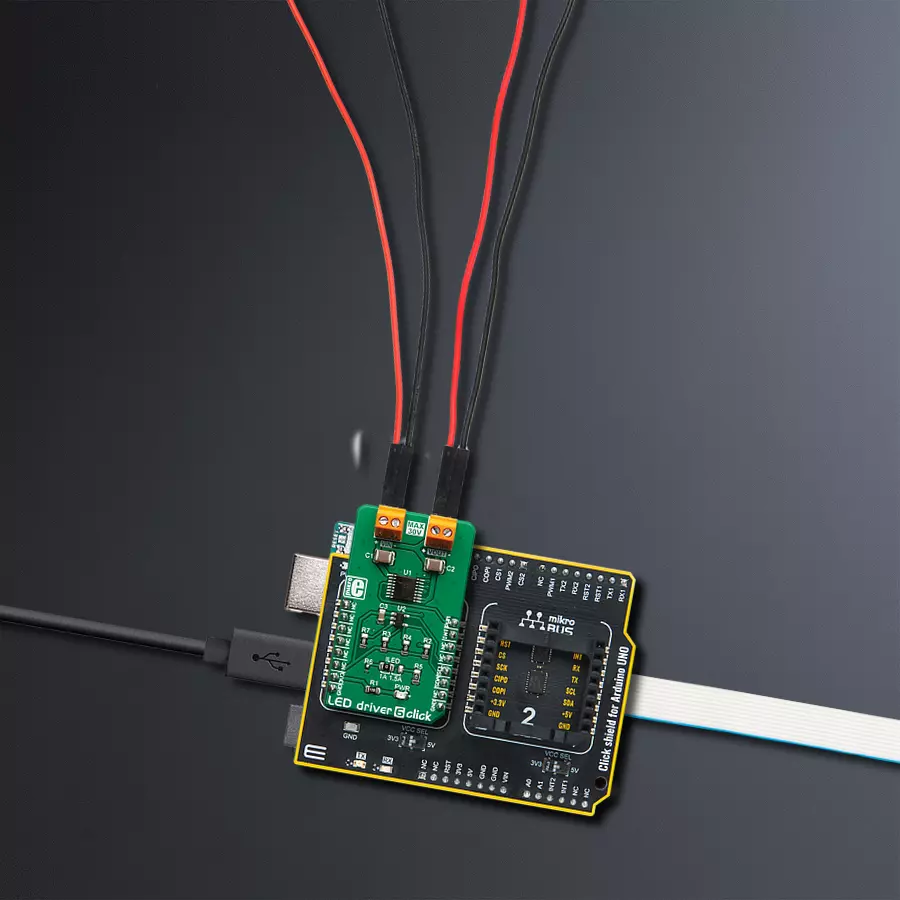
LED Driver 6 Click
Dev. board
Arduino UNO Rev3
Compiler
NECTO Studio
MCU
ATmega328P
Enable easy control and customization of LED-based features in your electronic gadgets with our flexible LED driver
A
A
Hardware Overview
How does it work?
LED Driver 6 Click is based on the AL1781, a single-channel PWM dimmable linear LED driver by Diodes Incorporated. It is a constant-current driver, which can sink up to 1500mA. It has a low-side current sink, which allows LED strips or LED bulbs to be connected in the common-anode topology for increased effectiveness and power optimization. The constant current through the connected LED can be selected by an SMD jumper labeled as ILED between two values: 1A and 1.5A. The AL1781 IC can be operated with a PWM signal in the frequency range from 1kHz to 40kHz. Applying the PWM signal with a duty cycle of less than 4ms makes it possible to tune the light intensity of the connected LED light element. A LOW pulse width of more than 4ms will set the device into the low-power mode (suspend). The lowest light intensity that can be reached by applying the PWM frequency of 1kHz is 0.1%, while 40kHz allows the lowest brightness level of 4% of the full light intensity. A High PWM frequency allows for less visible flickering but simultaneously limits the lowest light intensity level. PWM1 and PWM2 pins of the AL1781 are routed to the mikroBUS™ PWM and CS pins and are labeled as PW1 and PW2. Adaptive Thermal Management (ATM) scheme is one of the key features of the AL1781. It can be used to optimize the power
consumption by adjusting the voltage of the external power supply unit (PSU): the excessive voltage applied to the connected LED will be dissipated as heat within the AL1781 IC. Therefore, the voltage level of the external PSU should be kept above the forward voltage of the connected LED plus minimum voltage headroom (VF + VLED_REG). The ATM injects current through the LEDPG pin of the AL1781. This current is converted to a voltage level, and it is sampled by the MCP3221, a low-power 12-bit A/D converter with an I2C interface, by Microchip. It has its I2C pins routed to the respective mikroBUS™ I2C pins, allowing the host MCU to read the LEDPG voltage and adjust the PSU voltage. Please note that if an external PSU with no external regulation is used, its voltage should stay within the mentioned range (VF of the connected LED element + VLEDx_REG as per AL1781 datasheet). However, the voltage should always stay below 30V. The AL1781 IC also integrates many protection features for increased reliability: undervoltage, open or short circuit at the output, and thermal protection. If any of these protections become activated, a fault event will be reported on a dedicated pin labeled FAULTB. This pin is routed to the mikroBUS™ INT pin and is asserted to a LOW logic level when a fault event occurs. Deep Dimming
Capability helps with power efficiency. Subjective perception of the light intensity differs from the measured light. For example, the light intensity of 10% (with respect to the applied duty cycle) is perceived as 32% of the full light intensity. Deep Dimming Capability helps with energy saving, providing an optimal light output. Deep Dimming down to 0.1% is possible with the AL1781 IC since it can be operated with a pulse width as low as 1µS while still providing good linearity. LED driver 6 Click is designed to use an external PSU and an MCU. The full potential of the LED driver 6 Click is achieved when combined with a dedicated ambient light sensing Click board™ such as Ambient 5 Click: by receiving information about the ambient light intensity from Ambient 5 Click, the MCU can generate PWM signal with respect to the required intensity tuning and send it to LED driver 6 Click to regulate the intensity of the ambient lighting. This Click board™ can be operated only with a 3.3V logic voltage level. The board must perform appropriate logic voltage level conversion before using MCUs with different logic levels. Also, it comes equipped with a library containing functions and an example code that can be used as a reference for further development.

Features overview
Development board
Arduino UNO is a versatile microcontroller board built around the ATmega328P chip. It offers extensive connectivity options for various projects, featuring 14 digital input/output pins, six of which are PWM-capable, along with six analog inputs. Its core components include a 16MHz ceramic resonator, a USB connection, a power jack, an
ICSP header, and a reset button, providing everything necessary to power and program the board. The Uno is ready to go, whether connected to a computer via USB or powered by an AC-to-DC adapter or battery. As the first USB Arduino board, it serves as the benchmark for the Arduino platform, with "Uno" symbolizing its status as the
first in a series. This name choice, meaning "one" in Italian, commemorates the launch of Arduino Software (IDE) 1.0. Initially introduced alongside version 1.0 of the Arduino Software (IDE), the Uno has since become the foundational model for subsequent Arduino releases, embodying the platform's evolution.

Microcontroller Overview
MCU Card / MCU

Architecture
AVR
MCU Memory (KB)
32
Silicon Vendor
Microchip
Pin count
28
RAM (Bytes)
2048
You complete me!
Accessories
Click Shield for Arduino UNO has two proprietary mikroBUS™ sockets, allowing all the Click board™ devices to be interfaced with the Arduino UNO board without effort. The Arduino Uno, a microcontroller board based on the ATmega328P, provides an affordable and flexible way for users to try out new concepts and build prototypes with the ATmega328P microcontroller from various combinations of performance, power consumption, and features. The Arduino Uno has 14 digital input/output pins (of which six can be used as PWM outputs), six analog inputs, a 16 MHz ceramic resonator (CSTCE16M0V53-R0), a USB connection, a power jack, an ICSP header, and reset button. Most of the ATmega328P microcontroller pins are brought to the IO pins on the left and right edge of the board, which are then connected to two existing mikroBUS™ sockets. This Click Shield also has several switches that perform functions such as selecting the logic levels of analog signals on mikroBUS™ sockets and selecting logic voltage levels of the mikroBUS™ sockets themselves. Besides, the user is offered the possibility of using any Click board™ with the help of existing bidirectional level-shifting voltage translators, regardless of whether the Click board™ operates at a 3.3V or 5V logic voltage level. Once you connect the Arduino UNO board with our Click Shield for Arduino UNO, you can access hundreds of Click boards™, working with 3.3V or 5V logic voltage levels.

Used MCU Pins
mikroBUS™ mapper
Take a closer look
Click board™ Schematic

Step by step
Project assembly

Start by selecting your development board and Click board™. Begin with the Arduino UNO Rev3 as your development board.


Software Support
Library Description
This library contains API for LED Driver 6 Click driver.
Key functions:
leddriver6_set_duty_cycle- Generic sets PWM duty cycleleddriver6_pwm_stop- Stop PWM moduleleddriver6_pwm_start- Start PWM module.
Open Source
Code example
The complete application code and a ready-to-use project are available through the NECTO Studio Package Manager for direct installation in the NECTO Studio. The application code can also be found on the MIKROE GitHub account.
/*!
 * @file
 * @brief Leddriver6 Click example
 *
 * # Description
 * This application designed to be used in tunable Smart Connected Lighting applications.
 *
 * The demo application is composed of two sections :
 *
 * ## Application Init
 * Initializes I2C driver and PWM driver for the LED driver 6 control.
 *
 * ## Application Task
 * This is an example that demonstrates the use of the LED Driver 6 Click board.
 * This example shows the automatic control LED light intensity,
 * the first intensity of light is rising and then the intensity of light is falling.
 * Results are being sent to the Usart Terminal where you can track their changes.
 *
 * @author Nikola Peric
 *
 */

#include "board.h"
#include "log.h"
#include "leddriver6.h"

static leddriver6_t leddriver6;
static log_t logger;

void application_init ( void )
{
    log_cfg_t log_cfg;

    /**
     * Logger initialization.
     * Default baud rate: 115200
     * Default log level: LOG_LEVEL_DEBUG
     * @note If USB_UART_RX and USB_UART_TX
     * are defined as HAL_PIN_NC, you will
     * need to define them manually for log to work.
     * See @b LOG_MAP_USB_UART macro definition for detailed explanation.
     */
    LOG_MAP_USB_UART( log_cfg );
    log_init( &logger, &log_cfg );
    log_info( &logger, "---- Application Init... ----" );

    leddriver6_cfg_t leddriver6_cfg;

    //  Click initialization.

    leddriver6_cfg_setup( &leddriver6_cfg );
    LEDDRIVER6_MAP_MIKROBUS( leddriver6_cfg, MIKROBUS_1 );

    if ( leddriver6_init( &leddriver6, &leddriver6_cfg ) == LEDDRIVER6_INIT_ERROR )
    {
        log_info( &logger, "---- Application Init Error. ----" );
        log_info( &logger, "---- Please, run program again... ----" );

        for ( ; ; );
    }

    log_info( &logger, "---- Application Init Done. ----" );

    leddriver6_set_duty_cycle ( &leddriver6, 0.0 );
    if ( leddriver6_pwm_start( &leddriver6 ) == LEDDRIVER6_INIT_ERROR )
    {
        log_info( &logger, "---- PWM can't be started. ----" );
        log_info( &logger, "---- Please, run program again... ----" );

        for ( ; ; );
    }

    log_info( &logger, "---- PWM is started. ----" );
    log_info( &logger, "---- Application Task ----" );
    Delay_ms ( 500 );
}

void application_task ( void )
{
    static int8_t duty_cnt = 1;
    static int8_t duty_inc = 1;
    float duty = duty_cnt / 10.0;

    leddriver6_set_duty_cycle ( &leddriver6, duty );
    log_printf( &logger, "Duty: %d%%\r\n", ( uint16_t )( duty_cnt * 10 ) );
    Delay_ms ( 500 );

    if ( 10 == duty_cnt )
    {
        duty_inc = -1;
    }
    else if ( 0 == duty_cnt )
    {
        duty_inc = 1;
    }
    duty_cnt += duty_inc;
}

int main ( void )
{
    /* Do not remove this line or clock might not be set correctly. */
    #ifdef PREINIT_SUPPORTED
    preinit();
    #endif

    application_init( );

    for ( ; ; )
    {
        application_task( );
    }

    return 0;
}

// ------------------------------------------------------------------------ END
Additional Support
Resources
Category:LED Drivers


