Experience the future of lighting innovation with MCP1643 and STM32F031K6
Light up your world!

Published Oct 01, 2024
Click board™
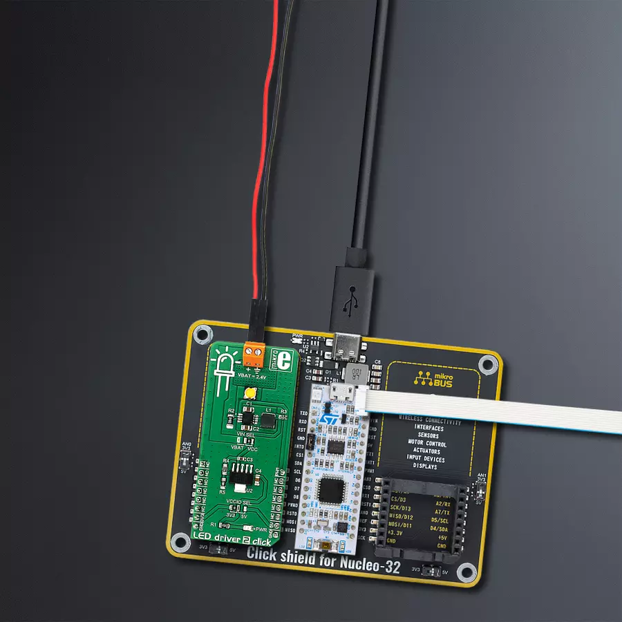
LED Driver 2 Click
Dev. board
Nucleo 32 with STM32F031K6 MCU
Compiler
NECTO Studio
MCU
STM32F031K6
With our LED driver solution and integrated LED, you can effortlessly enhance user experiences, create custom lighting effects, and ensure clear and intuitive status indications in your projects.
A
A
Hardware Overview
How does it work?
LED driver 2 Click is based on the MCP1643, an LED constant current regulator from Microchip. It is a compact, high-efficiency, fixed frequency, synchronous step-up converter optimized to drive one LED with a constant current. It can be powered by a two-cell alkaline/NiMH/NiCd battery (2.4V) or via the mikroBUS™ power supply pins. LED Driver 2 click also features a 3W High-brightness LED by QT-Brightek. This LED can be dimmed by applying the variable duty cycle PWM signal to the EN pin of the MCP1643 regulator through the PWM pin of the mikroBUS™. MCP1643 is a boost regulator with a low voltage reference of 120mV (VFB). The main feature of the regulator is that it is optimized to keep the current running through the LED - constant by regulating the voltage across the feedback resistor. The VFB pin regulates the voltage across the feedback
resistor to 120 mV, keeping the output LED current regulated. As the feedback resistor (R2 on the provided schematic) is connected to the FB pin and its resistance is 0.4Ω, the maximum current through the LED can easily be calculated by using the following formula: ILED = VFB/R2 = 120mV/0.4Ω = 300mA. The voltage drop on the feedback resistor has to be low to avoid dissipation. In the case of MCP1643, this voltage is set to 120mV, ensuring no dissipation issues. The onboard VIN SEL SMD jumper offers the selection of the input voltage source: it can be set to use a two-cell NiMH battery connected to the VIN terminal (2.4V) or the power supply pin from the mikroBUS™. The voltage from the mikroBUS™ can be set with the VCCIO SMD jumper to either 5V or 3.3V. Since the forward voltage on the high-power LED is 3.2V, the click board comes equipped with the MCP1826,
an LDO regulator by Microchip, which is used to drop the selected mikroBUS™ voltage down to around 2.4V so that the MPC1643 input voltage requirements are met. High brightness 3W LED is already attached to the output of the MCP1643, and it comes soldered on the board, so the circuit is ready to be used immediately. The LED brightness can be regulated by applying a variable duty cycle PWM signal to the EN pin of the MCP1643 regulator (routed to the PWM pin on the mikroBUS™). This changes the current running through the LED linearly, from 0 to the value set by the resistor, depending on the PWM cycle. Also, this Click board™ comes equipped with a library containing easy-to-use functions and an example code that can be used as a reference for further development.

Features overview
Development board
Nucleo 32 with STM32F031K6 MCU board provides an affordable and flexible platform for experimenting with STM32 microcontrollers in 32-pin packages. Featuring Arduino™ Nano connectivity, it allows easy expansion with specialized shields, while being mbed-enabled for seamless integration with online resources. The
board includes an on-board ST-LINK/V2-1 debugger/programmer, supporting USB reenumeration with three interfaces: Virtual Com port, mass storage, and debug port. It offers a flexible power supply through either USB VBUS or an external source. Additionally, it includes three LEDs (LD1 for USB communication, LD2 for power,
and LD3 as a user LED) and a reset push button. The STM32 Nucleo-32 board is supported by various Integrated Development Environments (IDEs) such as IAR™, Keil®, and GCC-based IDEs like AC6 SW4STM32, making it a versatile tool for developers.

Microcontroller Overview
MCU Card / MCU

Architecture
ARM Cortex-M0
MCU Memory (KB)
32
Silicon Vendor
STMicroelectronics
Pin count
32
RAM (Bytes)
4096
You complete me!
Accessories
Click Shield for Nucleo-32 is the perfect way to expand your development board's functionalities with STM32 Nucleo-32 pinout. The Click Shield for Nucleo-32 provides two mikroBUS™ sockets to add any functionality from our ever-growing range of Click boards™. We are fully stocked with everything, from sensors and WiFi transceivers to motor control and audio amplifiers. The Click Shield for Nucleo-32 is compatible with the STM32 Nucleo-32 board, providing an affordable and flexible way for users to try out new ideas and quickly create prototypes with any STM32 microcontrollers, choosing from the various combinations of performance, power consumption, and features. The STM32 Nucleo-32 boards do not require any separate probe as they integrate the ST-LINK/V2-1 debugger/programmer and come with the STM32 comprehensive software HAL library and various packaged software examples. This development platform provides users with an effortless and common way to combine the STM32 Nucleo-32 footprint compatible board with their favorite Click boards™ in their upcoming projects.

Used MCU Pins
mikroBUS™ mapper
Take a closer look
Click board™ Schematic

Step by step
Project assembly

Start by selecting your development board and Click board™. Begin with the Nucleo 32 with STM32F031K6 MCU as your development board.


Software Support
Library Description
This library contains API for LED driver 2 Click driver.
Key functions:
leddriver2_set_duty_cycle- This function sets the PWM duty cycleleddriver2_pwm_stop- This function stops PWM moduleleddriver2_pwm_start- This function starts PWM module
Open Source
Code example
The complete application code and a ready-to-use project are available through the NECTO Studio Package Manager for direct installation in the NECTO Studio. The application code can also be found on the MIKROE GitHub account.
/*!
 * \file
 * \brief LedDriver2 Click example
 *
 * # Description
 * This app enables usage of compact, high-efficiency, fixed frequency,
 * synchronous step-up converter, optimized to drive one LED with the constant current.
 *
 * The demo application is composed of two sections :
 *
 * ## Application Init
 * Initialization driver enables - GPIO,
 * PWM initialization set PWM duty cycle and start PWM.
 *
 * ## Application Task
 * This is an example that demonstrates the use of the LED Driver 2 Click board.
 * This example shows the automatic control halogen bulb light intensity,
 * the first intensity of light is rising and then the intensity of light is falling.
 * Results are being sent to the Usart Terminal where you can track their changes.
 *
 * \author Nikola Peric
 *
 */
// ------------------------------------------------------------------- INCLUDES

#include "board.h"
#include "log.h"
#include "leddriver2.h"

// ------------------------------------------------------------------ VARIABLES

static leddriver2_t leddriver2;
static log_t logger;

// ------------------------------------------------------ APPLICATION FUNCTIONS

void application_init ( void )
{
    log_cfg_t log_cfg;
    leddriver2_cfg_t cfg;

    /**
     * Logger initialization.
     * Default baud rate: 115200
     * Default log level: LOG_LEVEL_DEBUG
     * @note If USB_UART_RX and USB_UART_TX
     * are defined as HAL_PIN_NC, you will
     * need to define them manually for log to work.
     * See @b LOG_MAP_USB_UART macro definition for detailed explanation.
     */
    LOG_MAP_USB_UART( log_cfg );
    log_init( &logger, &log_cfg );
    log_info( &logger, "---- Application Init ----" );

    //  Click initialization.

    leddriver2_cfg_setup( &cfg );
    LEDDRIVER2_MAP_MIKROBUS( cfg, MIKROBUS_1 );
    leddriver2_init( &leddriver2, &cfg );

    leddriver2_pwm_start( &leddriver2 );
}

void application_task ( void )
{
    static int8_t duty_cnt = 1;
    static int8_t duty_inc = 1;
    float duty = duty_cnt / 10.0;

    leddriver2_set_duty_cycle ( &leddriver2, duty );
    log_printf( &logger, "> Duty: %d%%\r\n", ( uint16_t )( duty_cnt * 10 ) );

    Delay_ms ( 500 );

    if ( 10 == duty_cnt )
    {
        duty_inc = -1;
    }
    else if ( 0 == duty_cnt )
    {
        duty_inc = 1;
    }
    duty_cnt += duty_inc;
}

int main ( void )
{
    /* Do not remove this line or clock might not be set correctly. */
    #ifdef PREINIT_SUPPORTED
    preinit();
    #endif

    application_init( );

    for ( ; ; )
    {
        application_task( );
    }

    return 0;
}


// ------------------------------------------------------------------------ END
Additional Support
Resources
Category:LED Drivers


